AMK AMKASYN AN Series User manual

AMKASYN
Digital Inverters in Modular Construction
Series AN / AZ / AW
Power Supply Modules AN xx / AN xxF
Technical manual
Rights reserved to make technical changes
4400.1E Part-No.: 25747
AMKASYN
VARIABLE SPEED DRIVES
Arnold Müller, Antriebs- und Steuerungstechnik GmbH & Co.KG, D-73230 Kirchheim/Teck,
Tel.: 07021/50 05-0, Telefax: 07021/50 05-176

AMKASYN Digital inverters in modular construction
Power supply modules AN 4.1 - AZ page 2
Contents
1AMKASYN SYSTEM OVERVIEW ....................................................................................3
2SAFETY INSTRUCTIONS ................................................................................................4
3POWER SUPPLY .............................................................................................................5
3.1 Power Supply modules AN xx / AN xxF specification (NEOZED fuses).......................5
3.2 Power Supply modules AN xxF specification (FERRAZ/NH fuses)...............................6
4DIMENSIONS POWER SUPPLY MODULES AN XX / AN XXF ......................................7
5FRONT VIEW POWER SUPPLY MODULES AN XX / AN XXF (OPTION)
(NEOZED FUSES) ............................................................................................................8
6BLOCK DIAGRAM AND CONNECTION DRAWING POWER SUPPLY MODULES
AN XX / AN XXF .............................................................................................................11
7WIRING POWER SUPPLY MODULES AN XX / AN XXF.............................................. 12
8FUNCTIONAL DESCRIPTION POWER SUPPLY MODULES ......................................13
9SIGNAL DESCRIPTION OF POWER SUPPLY MODULES ..........................................14
10 AN MODULE EXCHANGE .............................................................................................15
11 IMPRESSUM...................................................................................................................16

AMKASYN Digital inverters in modular construction
Power supply modules AN 4.1 - AZ page 3
1 AMKASYN System overview
S C
F L
T S
N K D A 1
D A 2
D A 3
D A 4
Q S C
Q T S
Q R F
SBM
U E
R F
AA1
AA2
AA3
AA4
Q U E
A Z - E A x
A Z - I G x
R S 2 3 2 /
R S 4 2 2 /
R S 4 8 5
( A Z - K 0 2 )
A Z - P S x
A Z - M C x
A Z
A N
A W
A W
Q E S
Q E F
E F
Q E S
Q E F
E F
U
V
W
P E
U
V
W
P E
3 x 4 0 0 V . . .
4 8 0 V
A Z - R 0 1 /
A Z - R 0 2
1 2 3 4
O p i o n
A N x x F
A Z - R C x
M
3
M
3
A C M o o r
P T C P T C
O p i o n a l
c a r d s
S i g n a l b s
P r o g r a m m a b l e c o n r o l l e r c a r d
C N C c a r d
E F P o w e r o u p u e n a b l e
Q E F P o w e r o u p u e n a b l e d
Q E S P o w e r o u p u d i s a b l e d
Q U E
Q R F
S B M
Q S C
Q T S
D A 1 . . .
D A 4
D C - B u s r e a d y h a n d s h a k e
I n v e r e r s r e a d y h a n d s h a k e ( a l l )
S y s e m r e a d y
S C h a n d s h a k e
T S h a n d s h a k e
D a a o u p u D A 1 . . . D A 4
A b b r e v i a t i o n s :
U E
R F
F L
S C
T S
NK
D C - B u s e n a b l e
I n v e r e r s o n ( a l l )
E r r o r r e s e
S a u s c o d e c a l l
S a u s c o d e c l o c k
C a m ( R e f . L . S . )
P o w e r b s
P o w e r
s p p l y
m o d l e
( o p t i o n )
C e n t r a l m o d l e I n v e r t e r m o d l e
A n a l o g
o u p u s
1 2 b i
+ / - 1 0 V
B i n a r y
o u p u s
o p i c a l l y
i s o l a e d
B i n a r y i n p u s
o p i c a l l y
i s o l a e d
S q u a r e w a v e
p u l s e i n p u
B i n a r y I / O
c a r d
S q u a r e w a v e p u l s e i n p u c a r d
S E R C O S i n e r f a c e c a r d
I n v e r t e r m o d l e
( m a x . 8 )
P o w e r
o u p u
e n a b l e
A 1 A n a l o g i n p u
A 2 1 2 b i + / - 1 0 V
G 1 , . . . M o o r
e n c o d e r
P o w e r
o u p u
e n a b l e
A 1 A n a l o g i n p u
A 2 1 2 b i + / - 1 0 V
G 1 , . . . M o o r
e n c o d e r
O p i o n A W - I W x
p u l s e r a n s m .
O p i o n A W - I W x
p u l s e r a n s m .
A C M o o r
The AMKASYN series is a drive system of modular construction for feeding AMK AC motors.
The digital inverters regulate the drives in 4 quadrant mode precisely and with high dynamic
response. The feed is direct from a 400V three-phase power supply. The inverter modules
are supplied from a common DC-bus. The latest power semiconductor technology in
conjunction with high-grade integration guarantees high reliability.

AMKASYN Digital inverters in modular construction
Power supply modules AN 4.1 - AZ page 4
2 Safety instructions
Please read and observe additionally the „Safety instructions for AMKASYN
Inverters“.
Meaning of the used symbols:
Possible consequences: Dead or severest injuries!
Danger
Possible consequences: Severe injuries or death!
Warning
The operation of the drive system in a manner that does not conform to
its purpose and intended use can be dangerous and can cause severe
injury, up to loss of life, to the user/operator. Misuse can also cause
damage to the machinery/equipment of the enduser.
In order to minimize the risk of accidents and damage it is necessary that
installation, start-up, maintenance and repairs are performed diligently by
trained and experienced specialists.
Drive system parameters may only be set or modified by the machine
manifacturer!
Entry of non-conforming parameter values is effecting the drive behaviour
and increasing the risk of accidents and damage!
Each time before working on the AMKASYN drive system:
Interrupt power supply using the MASTER SWITCH!
Working under voltage is dangerous to life!
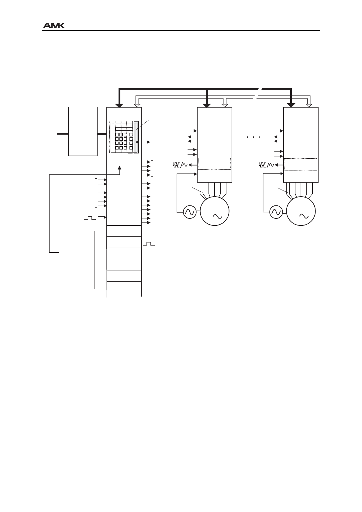
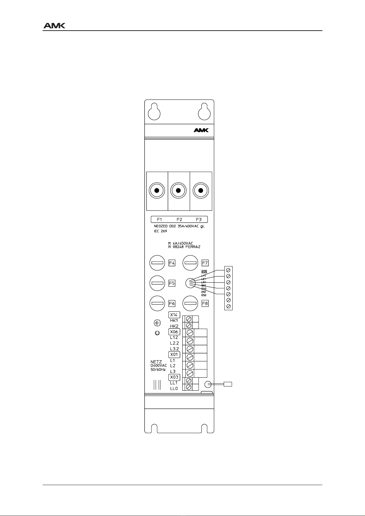
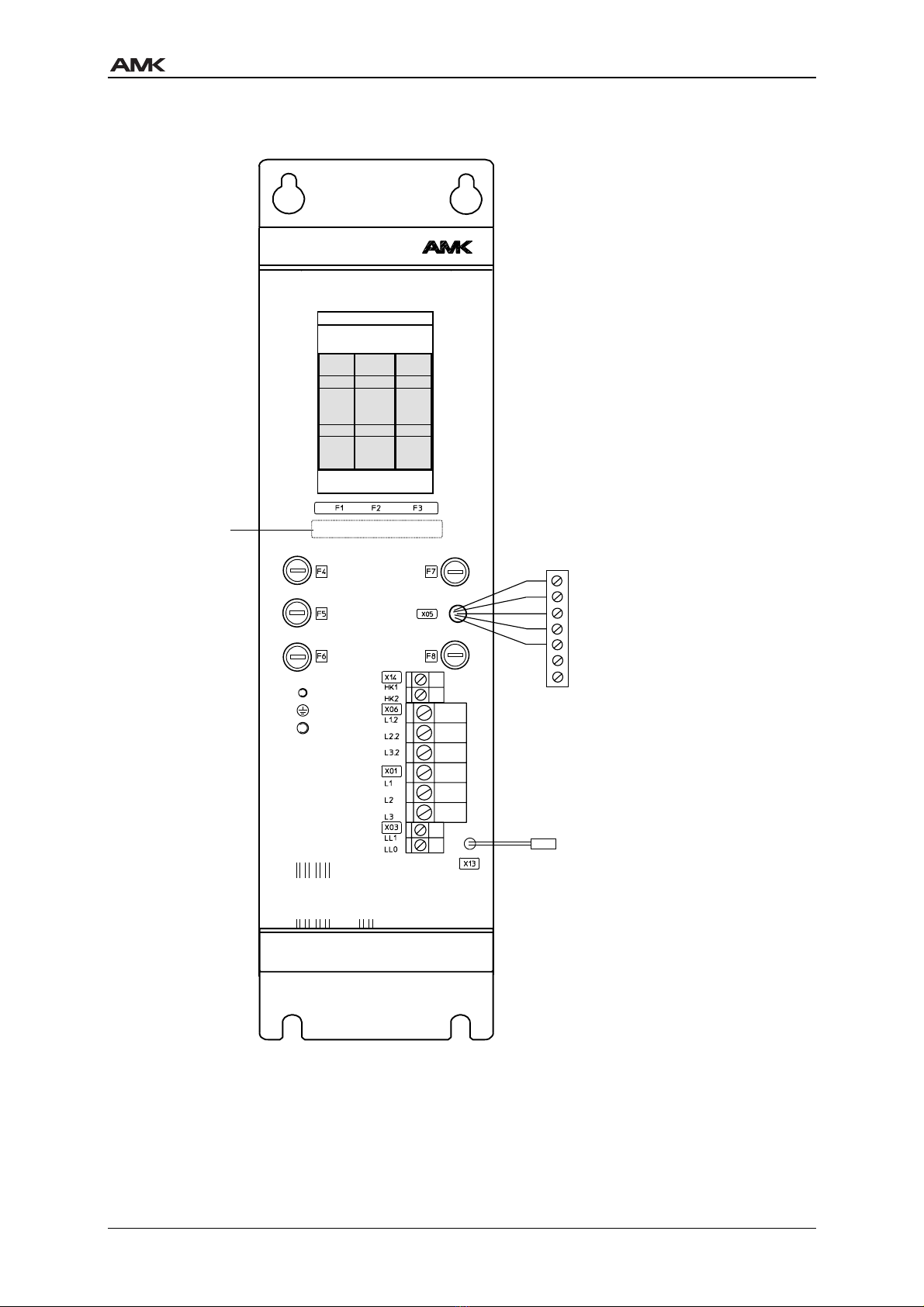
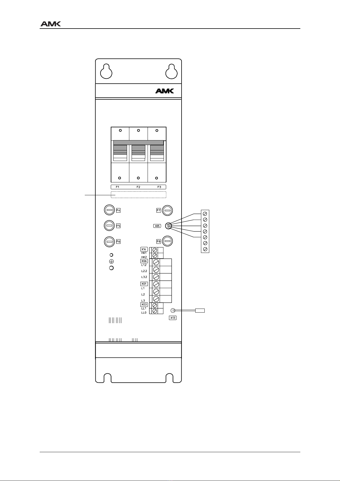
More than ONE LIVE CIRCUIT! See diagram! (2 line circuits on AZ module
X01, X03).
After POWER OFF:
Because of capacitor charge don’t touch electrical connections
immediately! DC voltage at terminals UZP and UZN is dangerous to life!
Before working on the modules wait for discharge time longer than
3 minutes after turning power off!
The option cards and all plug connectors must only be inserted or removed when the
modules are voltage-free!
Never loosen or tighten terminals under voltage!
Warning
Danger

AMKASYN Digital inverters in modular construction
Power supply modules AN 4.1 - AZ page 5
3 Power Supply
3.1 Power Supply modules AN xx / AN xxF specification
(NEOZED fuses)
The size of the power supply module AN xx depends upon the output power of the selected
central module AZ xx assigned. The value „xx“ states the nominal DC-output power of the AZ
module.
Suffix „F“ is specifying power supply modules with integrated mains suppression filter for
radio interference level A according to EN55011.
Type AN 10 /AN 10F AN 20 /AN 20F AN 40 /AN 40F AN 60 /AN 60F
Associated AZ module AZ 10 AZ 20 AZ 40 AZ 60
Input voltage 3 x 400V ±10%
Fan, main contactor
supply
230V ±10%
Line frequency 47 - 63 Hz
Output voltage equal to input voltage
Output frequency equal to line frequency
Efficiency approx. 0.99
Input current 16 A 32 A 64 A 96 A
Main fuses F1, F2, F3
Type
20 A
NEOZED D02
gL IEC 269
35 A
NEOZED D02
gL IEC 269
80 A
NEOZED D03
gL IEC 269
100 A
NEOZED D03
gL IEC 269
Miniature fuses
F4, F5, F6, F7, F8
Make/size
M4A / 400V
FERRAZ R98248 6,3 x 32
Recommended cable
cross-sections [mm2] /
AWG
Cable cross-sections according to „Conductors Table 53.2
UL508C“. Use copper wires (75°C) only.
X01: Power input
X06: Connection AN-AZ
3 x 400V power
output
X05: Connection AN-AZ
Charging circuit
X13: Fan supply
4x2,5 /AWG12
3x2,5 /AWG12
5x1 / AWG16
2x0.75 /
AWG18
4x10 / AWG8
3x6 / AWG10
5x1 / AWG16
2x0.75 /
AWG18
4x25 / AWG4
3x16 / AWG4
5x1 / AWG16
2x0.75 /
AWG18
4x35*/AWG2
3x35 / AWG2 *
5x1 / AWG16
2x0.75 /
AWG18
X14: Aux. contact (NC)
main contactor
(max. 230V / 16 A)
max. 2 x 4
PE connection [mm2] /
AWG
4 / AWG10 6 / AWG8 25 / AWG2 25 / AWG2
Dimensions
H x B x D [mm3] / [in.3]
358 x 90 x 357 /
14.1 x 3.54 x 14.05
538 x 170 x 357 /
21.2 x 6.7 x 14.05
Weight m [kg]/[lb] AN 10.5 / 23 10.5 / 23 16 / 35 17 / 37.5
AN...F 11.1 / 24.3 11.1 / 24.3 20.5 / 44.9 27.7 / 60.7
* End of wires with pin-end connector

AMKASYN Digital inverters in modular construction
Power supply modules AN 4.1 - AZ page 6
3.2 Power Supply modules AN xxF specification (FERRAZ/NH fuses)
Type AN 10
F -1 -1
AN 20
F -1 -1
AN 40
F -1
AN 40
F -1 -1
AN 60
F -1
AN 60
F -1 -1**
Associated AZ module AZ 10 AZ 20 AZ 40 AZ 40 AZ 60 AZ 60
Input voltage 3 x 400V ... 3 x 480V ±10%
Fan, main contactor
supply
230V ±10%
Line frequency 47 - 63 Hz
Output voltage equal to input voltage
Output frequency equal to line frequency
Efficiency ca. 0,99
Input current 16 A 32 A 64 A 64 A 96 A 96 A
Main fuses
F1, F2, F3
Type
25A
URC
Gr. 14x 51
FERRAZ
Y 093907
50A
URC
Gr. 14x 51
FERRAZ
B 093910
80A
NH-
Sicherung
gL Gr.000
IEC 269
80A
URD
Gr. 22x 58
FERRAZ
A 094829
100A
NH-
Sicherung
gL Gr.000
IEC 269
100A
URD
Gr. 22x 58
FERRAZ
Y 094827
Miniature fuses
F4, F5, F6, F7, F8
Make/Size
FF 6,3A / 500V
FERRAZ A 085445 6,3 x 32
Recommened cable
cross-sections [mm2] /
AWG
X01: Power input
X06: Connection AN-AZ
3 x 400V power
output
X05: Connection AN-AZ
Charging circuit
X13: Fan supply
4 x 2,5/
AWG12
3 x 2,5/
AWG12
5 x 1/
AWG16
2 x 0,75/
AWG18
4 x 10/
AWG8
3 x 6/
AWG10
5 x 1/
AWG16
2 x 0,75/
AWG18
4 x 25/
AWG4
3 x 16/
AWG4
5 x 1/
AWG16
2 x 0,75/
AWG18
4 x 25/
AWG4
3 x 16/
AWG4
5 x 1/
AWG16
2 x 0,75/
AWG18
4 x 35*/
AWG2
3 x 35*/
AWG2
5 x 1/
AWG16
2 x 0,75/
AWG18
4 x 35*/
AWG2
3 x 35*
AWG2
5 x 1/
AWG16
2 x 0,75/
AWG18
X14: Aux. Contact (NC)
main contactor
(max. 230V / 16A)
max. 2 x 4
PE-connection [mm2] /
AWG
4/
AWG10
6/
AWG8
25/
AWG2
25/
AWG2
25/
AWG2
25/
AWG2
Dimensions
H x B x T [mm]
358 x 90 x 357
14.1 x 3.54 x 14.05
538 x 170 x 357
21.2 x 6.7 x 14.05
Weight approx. [kg]/[Ib] 12 / 26,5 12 / 26,5 22 / 48,5 22 / 48,5 30 / 66,2 30 / 66,2
* End of wires with pin end connector.
** 60 kW only with 3 x 480V,
52 kW reduced power with 3 x 400V

AMKASYN Digital inverters in modular construction
Power supply modules AN 4.1 - AZ page 7
4 Dimensions Power Supply modules AN xx / AN xxF
X
A
B
Y
C
D
357
E
14.06"
0.275"
6,8
0.27"
3x45°
7
18 0.708"
7,8 0.3"
7
15 0.59"
Y
X
Ansicht
View
Ansicht
View
0.275"
AN10/
AN10F
90
(3.54")
170
(6.69")
60
(2.36")
415
(16.34")
415
(16.34")
595
(25.43")
400
(15.75")
400
(15.75")
580
(22.84")
358
(14.09")
358
(14.09")
538
(21.18")
ype
A
B
CD
E
AN20/
AN20F
AN40/
AN40F
AN60/
AN60F
90
(3.54")
170
(6.69")
60
(2.36")
140
(5.51")
140
(5.51")
595
(25.43")
580
(22.84")
538
(21.18")
15 0.59"

AMKASYN Digital inverters in modular construction
Power supply modules AN 4.1 - AZ page 8
5 Front view Power Supply modules AN xx / AN xxF (option)
(NEOZED fuses)
AN
F1,F2,F3
Input power
fuses
o AZ module
X25
F4,F5,F6
Fuses for
switch mode
power supply /
charging circuit
F7,F8
Fuses for
fan /
main contactor
o AZ module
X33
Input power
3x400V
Fan / main
contactor supply
230V
DC BUS supply
behind main
contactor
Aux. contact (n.c.)
main contactor

AMKASYN Digital inverters in modular construction
Power supply modules AN 4.1 - AZ page 9
Front view Power Supply modules AN xxF (NH fuses)
AN
3 x 400VAC ...
3 x 480 VAC
50 / 60Hz
230 VAC
50 / 60Hz
FF6.3A/500VAC
FERRAZ A 85445
F1, F2, F3
Input power
fuses ( NH )
to AZ module
X25
X14 Aux. contact (n.c.)
X01 Input power
X33
F5, F5, F6
Fuses for switch
mode power supply /
charging circuit
F7, F8
Fuses for fan /
main contactor
3x400 ... 480VAC
X03 Fan /
main contactor
230V
X06 DC BUS supply
behind main
contactor
main contactor
Fuse rating
Fuse type
to AZ module

AMKASYN Digital inverters in modular construction
Power supply modules AN 4.1 - AZ page 10
Front view Power supply modules AN xxF (FERRAZ fuses)
AN
FERRAZ
FERRAZ
FERRAZ
3 x 400VAC ...
3 x 480 VAC
50 / 60Hz
230 VAC
50 / 60Hz
FF6.3A/500VAC
FERRAZ A 85445
F1, F2, F3
Input power
fuses
to AZ module
X25
X14 Aux. contact (n.c.)
X01 Input power
X33
F5, F5, F6
Fuses for switch
mode power supply /
charging circuit
F7, F8
Fuses for fan /
main contactor
3x400 ... 480VAC
X03 Fan /
main contactor
230V
X06 DC BUS supply
behind main
contactor
main contactor
Fuse rating
Fuse type
to AZ module
( FERRAZ )

AMKASYN Digital inverters in modular construction
Power supply modules AN 4.1 - AZ page 11
6 Block diagram and connection drawing Power Supply modules
AN xx / AN xxF
L L 1
L L 0
P E
L 3
L 2
L 1
X 0 1
X 0 3
L 1 . 1
L 2 . 1
L 3 . 1
E H 1
E H 2
ES1
ES2
L 1 . 2
L 2 . 2
L 3 . 2
LL2
LL0
X 0 5
X 0 6
X 1 3
K D * )
H K 1
H K 2
X 1 4
R C
K 1
F 4
F 5
F 6
F 2
F 3
F 1
F 7
4 A
F 8
4 A
Z
S M P S / c h a r i n
c i r c u i t s u p p l y
M a i n c o n t a c t o r
O n
I n t e r r u p t i o n f o r
m a i n c o n t a c t o r
( b y c u s t o m e r )
F a n
P o w e r c i r c u i t
C h a r i n c i r c u i t
* ) L i n e r e a c t o r ( u = 4 % )
P o w e r i n p u t
3 x 4 0 0 V
C o i l v o l t a e
m a i n c o n t a c t o r : 2 3 0 V ~
( f r o m v e r s i o n 0 1 . 0 0 )
A u x .
c o n t a c t
k
Z : M a i n s s u p p r e s s i o n f i l t e r
( o n l y w i t h A N x x F )
F a n ( o n l y f o r
A N 4 0 F - 1 / F - 1 - 1
A N 6 0 F - 1 / F - 1 - 1 )

AMKASYN Digital inverters in modular construction
Power supply modules AN 4.1 - AZ page 12
7 Wiring Power Supply modules AN xx / AN xxF
ENTLADEZEIT
> 1 MIN:
1
5P
12P
12N
AZB
QUE
2
3
4
5
6
7
8
AZ-R01
X77
OPTIONEN
1
234
AZR
AZ
AN
PE ba
B ake esisto
Fan supply 230V
3x400V input powe
X24 PTC b ake esisto
X32 Squa e wave pulse
input
X77 AZ-R01 RS232C
X31 Bina y inputs
X29 Analog outputs
X30 Bina y inputs
to AZB cont ol
panel

AMKASYN Digital inverters in modular construction
Power supply modules AN 4.1 - AZ page 13
8 Functional description Power Supply modules
The power supply module AN is offered as option and contains all components that are
required for the power-side feed-in of the AMKASYN drive system.
The supply for generating the DC-BUS voltage is provided to the AZ module through the
main fuses F1, F2, F3, the main contactor K1 and the line reactor KD. The feed of the
switched mode power supply in the AZ module, fused via F4, F5, F6 is branched off before
the main contactor.
In the power supply module AN xxF a mains suppression filter is additionally integrated
which guarantees the conformity of the radio interference voltage’s limiting values according
to class A (EN 5501) for the AMKASYN system. It must however be provided, that cabling,
shielding and earthing are executed as instructed.
The AC voltage for the fans in the modules (230V, see „AN... specifications“) must be
provided by the customer at the terminals X03. F7 and F8 fuse the fan circuit.
On the power side, the terminals X06 in the AN module must be connected with the terminals
X26 in the AZ module. Insert plug-in terminal block X05 in the plug connector X25 and the
fan cable in socket X33.
If the power supply module AN option is not used, the corresponding components (fuses,
main contactor, line reactor) must be procured, installed and wired by the customer.
A main contactor with a pickup time of < 100 ms is required.

AMKASYN Digital inverters in modular construction
Power supply modules AN 4.1 - AZ page 14
9 Signal description of Power Supply modules
Terminals EH1, EH2, ES1, ES2
A relay contact in the central module AZ bridges terminals EH1 and EH2 on the plug-in
terminal block X05 and thus energizes the main contactor coil. Terminals ES1-ES2 are
connected in series to the contactor coil. The loop ES1-ES2 must be closed by the customer
by the contact of a safety time relay. The main contactor supply is interrupted on the
hardware side by separating the connection ES1-ES2.
The user thus has the possibility of isolating the drive system on the power side from the
power supply by an external safety circuit. The input of the switched mode power supply is
not interrupted in this case and axis-specific data is retained.
Input RF „Inverters On“ must be switched off before or simultaneously with the interruption of
ES1-ES2. The drive system goes to fault without this measure. It must be noted that
regenerative braking is possible only with the main contactor closed! If the safety regulations
require direct shutdown of the main contactor, an external braking resistor which converts
surplus braking energy into heat must be connected to the AZ module should the internal
braking resistor not be sufficient.
Terminals HK1, HK2 (from AN version 01.00)
Auxiliary contact (n.c.) of main contactor. External evaluation by the higher ranking controller.

AMKASYN Digital inverters in modular construction
Power supply modules AN 4.1 - AZ page 15
10 AN module exchange
Important information:
1. MASTER SWITCH OFF. AWAIT DC BUS DISCHARGING TIME > 3 MINUTES!
2. Remove module front cover.
3. Loosen strain relief for the cables.
Unscrew terminals for power input (X01) and fan supply (X03).
4. Unscrew terminals X06 (and X14 if used).
5. Use extracting tool to disconnect plug-in terminal block X25 at AZ module.
6. Disconnect fan connector X33 at AZ module. For this loosen the latching at the narrow
edge by pressing with your fingers.
7. Unscrew PE connections at AN module.
8. Loosen module fastening screws at the mounting panel.
9. Slightly lift the module and take it out towards you.
10. Insert the new AN module with the same specification, lower it and securely tighten the
fastening screws.
11. Securely tighten PE connections at AN module.
12. Insert and latch fan connector (X33) at AZ module.
13. Insert plug-in terminal block X25 at AZ module.
14. Securely connect the single wires at terminals X06 (and X14 if used).
Pay attention to the correct phase-sequence!
15. Securely connect power input at terminal X01 and fan supply at X03.
Pay attention to the correct phase-sequence!
16. For strain relief fix all cables to the bases with cable ties.
17. Put in the module front cover.
18. Main switch on. Restart.

AMKASYN Digital inverters in modular construction
Power supply modules AN 4.1 - AZ page 16
11 Impressum
Title AMKASYN Power supply modules AN
Objective Technical Description AMKASYN Power supply modules
AN xx / AN xxF / AN xxF-1 (-1)
Part-Number 25747
History Date
2000/44
Copyright ©AMK GmbH & Co. KG
No part of this document may be reproduced or transmitted in any form or by
any means, electronic or mechanical, for any purpose without the express
written permission of AMK GmbH + Co. KG. Violations are subject to legal
action. All rights in case of patent filings or user-sample registrations are
reserved.
Disclaimer We reserve the right to change the contents of the documentation and the
availability of products at any time without prior notice.
Service Tel.: +49/(0)7021 / 5005-191, Fax –193
Business Hours:
Mo-Fr 7.30 - 16.30, On weekends and holidays calls are forwarded to an emergency
response number by the automated answering system.
To assure a fast and accurate response to solve customer problems we ask for your
cooperation in providing us with the following information:
• Nameplate data
• Software version
• System configuration and application
• Description of problem and presumed cause of failure
• Diagnostic message ( error code )
Publisher AMK Arnold Müller Antriebs- und Steuerungstechnik GmbH & Co. KG
Gaußstraße 37 – 39, 73230 Kirchheim/Teck
Tel.: 07021/5005-0, Fax: 07021/5005-176
E-Mail: [email protected]
For further information www.amk-antriebe.de
This manual suits for next models
10
Table of contents