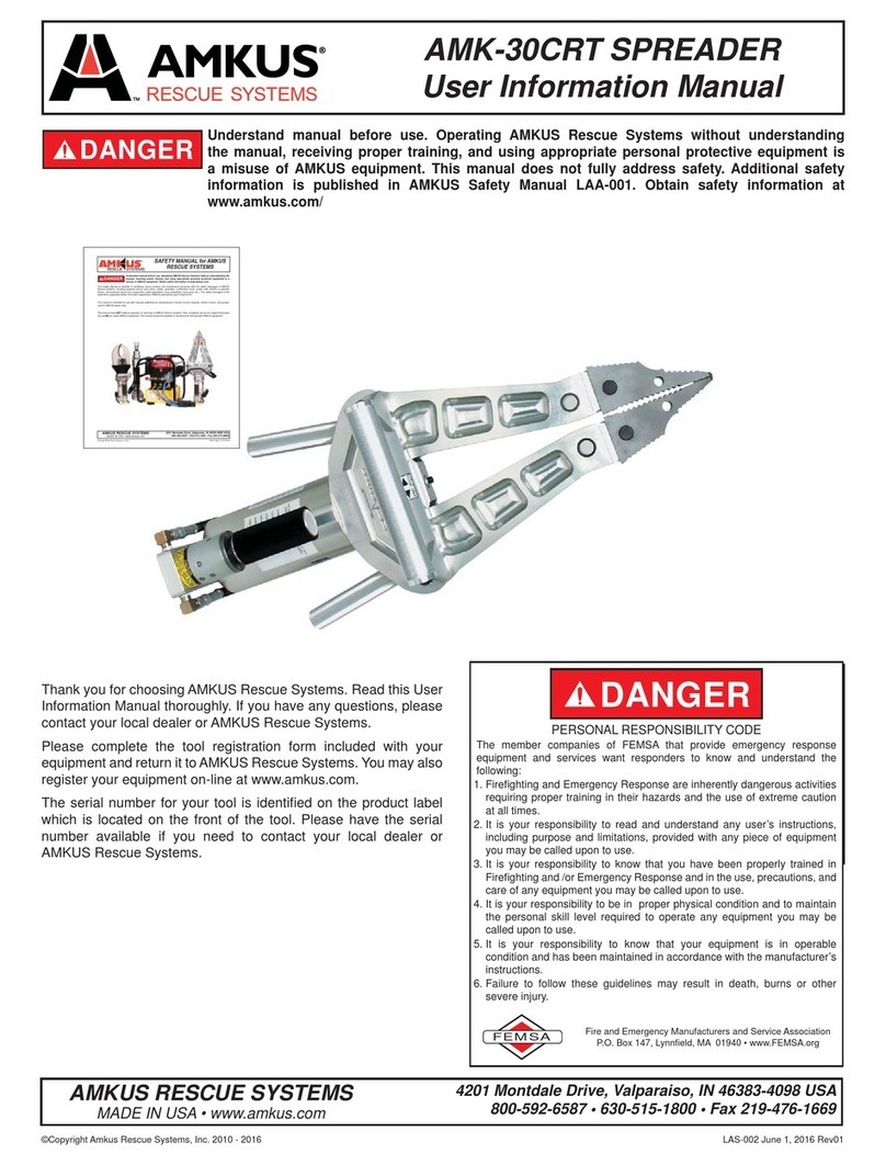
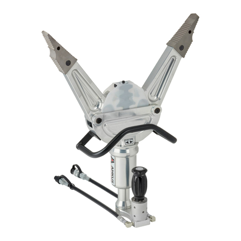
Amkus AMK-30CRT Series User manual

©Copyright AMKUS Rescue Systems, Inc. 2010 - 2019 LAS-002 August 19, 2019 Rev03
DANGER Understand manual before use. Operating AMKUS Rescue Systems without understanding
the manual, receiving proper training, and using appropriate personal protective equipment is
a misuse of AMKUS equipment. This manual does not fully address safety. Additional safety
information is published in AMKUS Safety Manual LAA-001. Obtain safety information at
amkus.com/resources/documentation
AMK-30CRT shown with optional lighted handle
* This tool has been discontinued
MANUAL: AMK-30CRT
AMK-30CX SPREADER
AMKUS RESCUE SYSTEMS
amkus.com
4201 Montdale Drive, Valparaiso, IN 46383-4098 USA
800-592-6587 • 219-548-5000 • Fax 219-476-1669
AMK-30CRT SPREADER STD CPL
AMK-30CRT-L SPREADER STD CPL - LIGHTED HANDLE
AMK-30CRTM SPREADER MONO CPL
AMK-30CRTM-L SPREADER MONO CPL - LIGHTED HANDLE
AMK-30CX* SPREADER STD CPL
AMK-30CXM* SPREADER MONO CPL
AMK-30CX models do not have removable tips

©Copyright AMKUS Rescue Systems, Inc. 2010 - 2019 LAS-002 August 19, 2019 Rev03
2
DANGER
PERSONAL RESPONSIBILITY CODE
The member companies of FEMSA that provide emergency response
equipment and services want responders to know and understand the
following:
1. Firefi ghting and Emergency Response are inherently dangerous activities
requiring proper training in their hazards and the use of extreme caution
at all times.
2. It is your responsibility to read and understand any user’s instructions,
including purpose and limitations, provided with any piece of equipment
you may be called upon to use.
3. It is your responsibility to know that you have been properly trained in
Firefi ghting and /or Emergency Response and in the use, precautions, and
care of any equipment you may be called upon to use.
4. It is your responsibility to be in proper physical condition and to maintain
the personal skill level required to operate any equipment you may be
called upon to use.
5. It is your responsibility to know that your equipment is in operable
condition and has been maintained in accordance with the manufacturer’s
instructions.
6. Failure to follow these guidelines may result in death, burns or other
severe injury.
FEMSA
Fire and Emergency Manufacturers and Service Association
P.O. Box 147, Lynnfi eld, MA 01940 • www.FEMSA.org
TABLE OF CONTENTS
1.0 MEANING OF SAFETY WORDS .......................................................................... 4
2.0 SPECIFICATIONS ................................................................................................4
3.0 PROTECTIVE CLOTHING ................................................................................... 4
4.0 TRAINING ............................................................................................................4
5.0 PART IDENTIFICATION ........................................................................................ 5
5.1 HANDLE LIGHTS OPTIONAL
6.0 OPERATION ..........................................................................................................7
7.0 SAFETY GUARDS ................................................................................................ 9
8.0 ROUTINE MAINTENANCE ................................................................................ 10
8.0.1 LUBRICATION
8.0.2 ANNUAL MAINTENANCE
8.1 ROUTINE MAINTENANCE FOR COUPLINGS
8.2 ROUTINE MAINTENANCE FOR HOSES
8.3 MAINTENANCE RECORDS
9.0 SET UP PROCEDURE ....................................................................................... 11
10.0 GETTING STARTED .......................................................................................... 11
11.0 GENERAL MAINTENANCE AND STORAGE ........................................................ 7
12.0 TROUBLESHOOTING GUIDE ............................................................................ 12
13.0 PARTS, SERVICE, TECHNICAL INFORMATION ...............................................12
14.0 INSPECTION, CLEANING, DECONTAMINATION, AND STORAGE .................. 12

©Copyright AMKUS Rescue Systems, Inc. 2010 - 2019 LAS-002 August 19, 2019 Rev03
3
ADDITIONAL MANUALS
©Copyright AMKUS Rescue Systems, Inc. 2016 LAA-001 April 15, 2016 Rev00
DANGER Understand manual before use. Operating AMKUS Rescue Systems without understanding the
manual, receiving proper training, and using appropriate personal protective equipment is a
misuse of AMKUS equipment. Obtain safety information at www.amkus.com/
This Safety Manual is intended to familiarize rescue workers and maintenance personnel with the safety messages of AMKUS
Rescue Systems, including powered rescue tools (rams, cutters, spreaders, combination tools), power units (electric or gasoline
driven), and powered rescue tool components (cable assemblies, hose assemblies, hose reels, etc.). The safety messages in this
publication supersede safety information appearing in AMKUS publications prior to April 2016.
This manual is intended for use with manuals published by manufacturers of prime movers (engines, electric motors, and pumps)
used in AMKUS power units.
This manual does NOT address operation or servicing of AMKUS Rescue Systems. Only competent rescue tool repair technicians
are quali¿ ed to repair AMKUS equipment. This manual should be available to all personnel involved with AMKUS equipment.
SAFETY MANUAL for AMKUS
RESCUE SYSTEMS
AMKUS RESCUE SYSTEMS
amkus.com
4201 Montdale Drive, Valparaiso, IN 46383-4098 USA
800-592-6587 • 630-515-1800 • Fax 219-476-1669
Safety Manual For AMKUS Rescue Systems
LAA-001
©Copyright AMKUS Rescue Systems, Inc. 2014-2016 LAA-004 December 8, 2016 Rev04
SAFETY DATA SHEET
According to OSHA Hazard Communication
Standard, 29 CFR 1910.1200
AMKUS RESCUE SYSTEMS
amkus.com
4201 Montdale Drive, Valparaiso, IN 46383-4098 USA
800-592-6587 • 219-548-5000 • Fax 219-476-1669
SECTION 1. IDENTIFICATION
DIULF CILUARDYH 1VM SUKMAemaN tcudorP
Manufacturers of suppliers details
AMKUS RESCUE SYSTEMS, INC.
4201 Montdale Drive
Valparaiso, IN 46383-4098 USA
0005-845-912tseuqeR SDS
Customer Service
Emergency telephone number
CERTMEHC 0039-424-008noitamrofn
I llipS
Health Information
Recommend use of the chemical and restrictions on use
lio ciluardyHesU dednemmoceR
SECTION 2. HAZARDS IDENTIFICATION
GHS Classi¿ cation
Not a hazardous substance or mixture
GHS Label element
deriuqer lobmys drazah oNsmargotcip drazaH
drow langis oNdrow
langiS
:SDRAZAH LACISYHPstnemetatS drazaH
Not classi¿ ed as a physical hazard under GHS criteria.
HEALTH HAZARDS:
Not classi¿ ed as a health hazard under GHS criteria.
ENVIRONMENTAL HAZARDS:
Not classi¿ ed as an environmental hazard under GHS criteria.
Precautionary statements
Prevention: No precautionary phrases.
Response: No precautionary phrases.
Storage: No precautionary phrases.
Disposal: No precautionary phrases.
Other hazards which do not result in classi¿ cation
Prolonged or repeated skin contact without proper cleaning can clog the pores of the skin resulting in disorders
such as oil acne/folliculitis.
Used oil may contain harmful impurities.
High-pressure injection under the skin may cause serious damage including local necrosis.
Not classi¿ ed as À ammable but will burn.
The classi¿ cation of this material is based on OSHA HCS 2012 criteria.
Under normal conditions of use or in a foreseeable emergency, this product does not meet the de¿ nition of
a hazardous chemical when evaluated according to the OSHA Hazard Communication Standard, 29 CFR
1910.1200.
Safety Data Sheet AMKUS MV1 Hydraulic Fluid
LAA-004

©Copyright AMKUS Rescue Systems, Inc. 2010 - 2019 LAS-002 August 19, 2019 Rev03
4
1.0 MEANING OF SAFETY SIGNAL WORDS
A safety related message is identifi ed by a safety alert symbol and a signal word to indicate the level of risk involved with a particular
hazard. Per ANSI standard Z535.6-2011, the defi nitions of the four signal words are as follows:
DANGER DANGER indicates a hazardous situation which, if not avoided, will result in death or serious
injury.
WARNING WARNING indicates a hazardous situation which, if not avoided, could result in death or serious
injury.
CAUTION CAUTION indicates a potentially hazardous situation which, if not avoided, could result in minor
or moderate injury.
NOTICE NOTICE is used to address practices not related to physical injury.
2.0 SPECIFICATIONS
Part # AMK-30CRT
MECHANICAL SPECIFICATIONS
Length 30.1 in. (765 mm)
Width 12.0 in. (305 mm)
Depth 8.2 in. (208 mm)
Weight (ready to use)
(Ready-to-use with Standard couplings)
48.0 lbs. (21.75 kg)
Weight (ready to use)
(Ready-to-use with Mono couplings)
48.5 lbs. (22.0 kg)
Maximum Spreader Opening 32.0 in. (813 mm)
Rated Input Pressure 10,500 psi (724 bar)
Fluid Type AMKUS MV-1 Mineral Based Hydraulic Fluid
(for equipment stored and operated in environments below
freezing, use AMKUS MV-0 Mineral Based Hydraulic Fluid)
Safety Data Sheet (SDS) for AMKUS MV1 Hydraulic Fluid is available
at AMKUS.com and CHEMTREC.com
3.0 PROTECTIVE CLOTHING
It is the responsibility of the user to insure that appropriate protective clothing and equipment are used to provide protection from
those hazards to which personnel are exposed or could be exposed while working with this product.
4.0 TRAINING
This product is designed to be used by emergency services personnel to facilitate the extrication of victims from entrapment. Its use
should be limited to trained personnel only. All personnel using this equipment are assumed to have completed a course of instruction
that is acknowledged as being educationally sound by the local authority having jurisdiction over such training. This document
contains basic operating and maintenance instructions only and is not intended to provide policy or methodology for use.

©Copyright AMKUS Rescue Systems, Inc. 2010 - 2019 LAS-002 August 19, 2019 Rev03
5
5.0 PART IDENTIFICATION
Protective Rack Cover
Side Handle
Tool Connection Hose
Front Handle
Control Valve Handgrip
Valve Manifold
OPENCLOSE
4201 Montdale Drive, Valparaiso, IN 46383-4098
800-592-6587 • 219-548-4000
KEL0001
UNDERSTAND MANUAL BEFORE USE.
OPERATING AMKUS RESCUE SYSTEMS
WITHOUT UNDERSTANDING THE
MANUAL, RECEIVING PROPER TRAINING,
AND USING APPROPRIATE PERSONAL
PROTECTION EQUIPMENT IS A MISUSE
OF AMKUS EQUIPMENT. OBTAIN SAFETY
INFORMATION AT WWW.AMKUS.COM
DANGER
SERIAL NO: K123456
DATE OF MFG: 04/2017
MODEL: AMK - 30CRT
SYSTEM PRESSURE:
10,500 PSI (724 BAR)
FLUID TYPE: AMKUS MV1
Mineral Based Hydraulic Fluid
5.1 HANDLE LIGHTS OPTIONAL
AMKUS dual handle lights operate at three levels of intensity. To operate these lights, press the button located behind each light. The
lights can be powered OFF by scrolling through each setting to OFF, or by a single button press from a setting that’s been powered
ON for over 5 seconds. Continuous use time is about 60 hours on low. Battery saver function will turn the lights off after 15 minutes
of continuous use.
Press Red Buttons on back:
1st light level low
2nd light level medium
3rd light level high
4th power off light
Figure 5.1

©Copyright AMKUS Rescue Systems, Inc. 2010 - 2019 LAS-002 August 19, 2019 Rev03
6
5.2 CONTROL VALVE
The control valve is equipped with a deadman safety feature, which causes the control valve to return to the OFF position (neutral)
when released (see fi g. 5.2). The movement of the tool will stop and hold its position and load. The control valve has three positions
(see fi g. 5.2)
CLOSE:
clockwise rotation
closes the tool
OFF (Neutral postion):
The control valve actuator returns to
the center with motor stopped
OPEN:
counter clockwise rotation
opens the tool
Figure 5.2
Verify operation of control valve by checking to see if it returns automatically to the neutral position.

©Copyright AMKUS Rescue Systems, Inc. 2010 - 2019 LAS-002 August 19, 2019 Rev03
7
6.0 OPERATION
6.1 SPREADING / SQUEEZING / LIFTING
Figure 6.1a
The spreader can be used for spreading, squeezing, pulling and lifting operations. When spreading, squeezing or lifting, make sure
that the spreader tips are positioned to maintain maximum contact with the surfaces to be spread or gripped. Always stabilize the
object being lifted. When operating the spreader, the tool may rotate as it meets resistance. If tool rotation places the user or others
in jeopardy, immediately release the control valve and modify your procedure. The deadman safety feature should immediately return
the control valve to the center (neutral) position, and the movement of the arms will stop. Then seek another purchase point that does
not cause the same problem.
TIPS MAY SLIP
INCREASE GAP AND
REPOSITION TIPS
CORRECT
STARTING POSITION
INCORRECT
STARTING POSITION
Figure 6.1b
See 6.2B for exchanging spreader tips

©Copyright AMKUS Rescue Systems, Inc. 2010 - 2019 LAS-002 August 19, 2019 Rev03
8
6.2 EXTENDED REACH SPREADER TIPS
The AMK-30CRT spreaders have removable tips. AMK-30CX spreaders don’t have removable tips, but they are upgradable. To
remove the spreader tip, use a thumb and fi nger to depress the spring loaded tip pins, and remove the tips. To re-install the spreader
tip, slide the tip back into place. Be sure that both pins return fully to their original positions.
The reach and versatility of the spreader can be increased by using the Extended Reach Tips (ERT). ERT tips are interchangeable
with the standard tips.
GATOR TIP ERT TIP COMBO TIP 1 COMBO TIP 2
Figure 6.2a
Figure 6.2b
6.3 CHAIN USE
Chain kits are available for spreaders with removable tips.
WARNING Transport chain is NOT rated for overhead lifting. Injury or death may occur from improper chain
use. Observe chain safety guidelines established by the Authority Having Jurisdiction.
Setup and operation of both chain kits are the same:
• Secure chains around the load removing slack using grab hooks to
latch fully across the chain (tip of hook must not to be inserted into
holes of the chain link)
• Remove slack in the chain using quick adjust links.
• Tension the chain slightly and check to see that the connections are
stable and safe
• Activate the control valve to close the arms and draw the load
Figure 6.3a
Chain rating; 3/8” grade 70 Transport chain, working load limit 6600 lbs (2994 kg)
RELEASE
LOCK
K-CHAIN24-30
Figure 6.3b Figure 6.3c

©Copyright AMKUS Rescue Systems, Inc. 2010 - 2019 LAS-002 August 19, 2019 Rev03
9
7.0 SAFETY GUARDS
WARNING Operating rescue tools can result in injury or death from laceration, projectile (high speed fl ying
debris) and pinch point injuries. Stay clear of the path of travel. Do not operate without guards.
Avoid unnecessary risk. (For examples, see LAA-001 Safety Manual For AMKUS Rescue Tools)
The spreader arms have a cover over the rack. The cover is secured with a screw and washer which can be removed to perform
maintenance. Replace cover after maintenance.
Guard
G
uar
d
Figure 7.0

©Copyright AMKUS Rescue Systems, Inc. 2010 - 2019 LAS-002 August 19, 2019 Rev03
10
8.0 ROUTINE MAINTENANCE
WARNING Avoid contact with escaping hydraulic fl uid under pressure. If hydraulic fl uid punctures skin,
seek medical treatment immediately. Contact with escaping hydraulic fl uid under pressure could
result in serous injury or death.
Inspect all hose, hoses fi ttings and couplings for leakage and damage (see routine maintenance for hoses and couplings). Check the
rotation of the control valve for smooth operation and automatic return to center. Fasteners should all remain secure. Check spreader
tips and replace if bite becomes ineff ective. Spring loaded spreader arm tip pins should depress under fi nger tip pressure. The pins
should extend fully to engage the spreader tips when released. Rusted or stuck pins need to be cleaned and lubricated.
8.0.1 LUBRICATION
Spring loaded spreader arm tip pins should be oiled with light machine oil. Cycle to restore free motion. Replace if spring action isn’t
restored contact your Authorized AMKUS dealer.
Spreader arms, racks, and pins are lubricated with white lithium grease. Annual re-lubrication is recommended for average service
conditions. More frequent lubrication may be required for severe or frequent usage conditions. Contact an Authorized AMKUS dealer
for annual maintenance and warranty needs.
8.0.2 ANNUAL MAINTENANCE
1. Annual maintenance shall be completed by an Authorized AMKUS dealer while the rescue tool is under warranty.
2. Contact the AMKUS dealer or AMKUS directly for replacement parts.
3. Always relieve the rescue tool of internal pressure prior to servicing.
8.1 ROUTINE MAINTENANCE FOR COUPLINGS
Keep hose couplings free of dirt and contaminants. Even with care, residual oils on the moving parts gradually accumulate dirt
and grit making hose connections difficult. To clean hose couplings, immerse in, or scrub with, an automotive type aerosol solvent
degreaser. Apply a light spray lube (automotive, lock, or gun type) to keep the collars moving easily. The rubber dust caps provided
with the tools should be cleaned periodically. Be aware, the hose couplings may be clean, yet the dust caps accumulate dirt during
use. Do not cover a clean hose coupling with a dirty dust cap.
8.2 ROUTINE MAINTENANCE FOR HOSES
WARNING Damaged hoses should be replaced immediately. Damaged hoses could cause hydraulic fl uid
to escape. Contact with escaping hydraulic fl uid under pressure could result in serious injury
or death. Loss of hydraulic pressure prevents the rescue tool from operating properly and may
result in serious injury or death.
After each use, wipe hydraulic hoses clean with a light cleaning solvent such as Simple Green®. Inspect hydraulic hoses for damage
to the outer rubber cover. Damage exposing the wire braided reinforcement subjects the wire to corrosion and may weaken the
hydraulic hose. Remove damaged hydraulic hoses from service. Replace damaged hydraulic hoses immediately.
8.3 MAINTENANCE RECORDS
It is a user’s responsibility to keep maintenance records for each component of the rescue system. Maintenance shall be performed
in accordance with the recommendations as outlined in this manual.

©Copyright AMKUS Rescue Systems, Inc. 2010 - 2019 LAS-002 August 19, 2019 Rev03
11
9.0 SET-UP PROCEDURE
AMKUS equipment is manufactured with superior craftsmanship and quality backed by a factory warranty.
NOTICE Only use AMKUS tools with AMKUS equipment. Mixing AMKUS tools with another manufacturer’s
equipment may cause operational problems, equipment failure, or denial of warranty claims.
NOTICE Only use AMKUS MV1 hydraulic fl uid in AMKUS equipment. Using another manufacturer’s
hydraulic fl uid in AMKUS equipment may cause operational problems, equipment failure, or
denial of warranty claims.
Normally, AMKUS equipment is prepared and serviced by your dealer prior to delivery. If, however, you have decided to place the
equipment into service yourself, please review the following instructions carefully.
1. Remove equipment from the packing cartons and carefully inspect for damage. Damage that occurs during shipment should be
reported immediately to the carrier.
2. Gather and review all safety and use documentation prior to operating any rescue tool.
3. Connect the tool connection hoses to the hose lines from the AMKUS hydraulic power unit.
a. If you have Standard Couplings: Please note that the male and female couplings on the hose lines leading from the power unit
should be connected to the corresponding male and female couplings on the tool connection hoses. To connect the couplings,
twist the sleeve on the female coupling so that the notch in the sleeve lines up with the pin. Push the sleeve back so the pin fi ts
into the notch. While holding the sleeve back, push the male coupling into the female coupling. Release the sleeve; it will spring
forward into place. Twist the sleeve 1/4 turn so that the pin no longer lines up with the notch. Pull on the couplings to check that
they are securely connected.
b1. If you have Mono Couplings: Please note that the female coupling on the hose lines leading from the power unit should be
connected to the corresponding male coupling on the tool connection hoses. To connect the couplings, place the male coupling
into the female coupling. Rotate clockwise until you feel the coupling latch. Pull on the couplings to check that they are securely
connected.
b2. In most cases, the Mono Couplings can be connected and disconnected while the hose line is under fl ow. It is usually not
necessary to place the directional control of the power unit in the neutral position before connecting and disconnecting.
However, certain circumstances such as back pressure in the return line and/or cold temperatures, may make connecting and
disconnecting under fl ow extremely diffi cult or impossible. If you are unable to connect and disconnect while the line is under
fl ow, place the directional control valve of the power unit in the neutral position and then disconnect or connect.
10.0 GETTING STARTED
WARNING Do not connect tools in series. Connecting tools in series could cause operational problems,
equipment failure, or catastrophic failure of the equipment resulting in serious injury or death.
Start the power unit (refer to power unit and engine manuals). Following the instructions in the power unit manual, operate the
selector valve to charge the hose line to which the tool is connected. Pick up the tool, noticing that the design of the AMK-30CRT
Spreader makes it natural to grip the handle with one hand and the control valve handgrip with the other.
11.0 GENERAL MAINTENANCE AND STORAGE
1. Always store the tool in a clean, dry space.
2. Never store a tool under pressure.
3. Store spreaders with a slight gap between the tips.
After each use:
1. Check to see that important tool markings are legible. Contact your local dealer or AMKUS Rescue Systems for replacement
labels.
2. Wipe tool, hoses, fi ttings and couplings clean (see routine maintenance for hoses and couplings).
3. Inspect the tool, hoses, fi ttings and couplings after each use for damage, leakage and excessive wear.
4. If damage or excessive wear is noticed, do not use the tool; contact your local dealer or AMKUS Rescue Systems..
WARNING Any rescue tool failing any part of the checklist is unsafe for use and must have the problem
corrected before use or being placed back into service. Operating a rescue tool that has failed the
checklist is a misuse of this equipment. Contact your local dealer or AMKUS Rescue Systems.

©Copyright AMKUS Rescue Systems, Inc. 2010 - 2019 LAS-002 August 19, 2019 Rev03
AMKUS RESCUE SYSTEMS
amkus.com
4201 Montdale Drive, Valparaiso, IN 46383-4098 USA
800-592-6587 • 219-548-5000 • Fax 219-476-1669
13.0 PARTS, SERVICE AND TECHNICAL INFORMATION
Parts, service and technical information may be obtained from your local AMKUS dealer, or by contacting AMKUS Rescue Systems.
14.0 INSPECTION, CLEANING, DECONTAMINATION, AND STORAGE
WARNING Any rescue tool failing any part of the checklist is unsafe for use and must have the problem
corrected before use or being placed back into service. Operating a rescue tool that has failed the
checklist is a misuse of this equipment. Contact your local dealer or AMKUS Rescue Systems.
1. Always store the tool securely in a clean dry space.
2. Never store a tools or power unit hoses under pressure. Always relieve the pressure on hoses and tools after use.
BEFORE BEING PLACED BACK IN SERVICE, rescue tools must be inspected to this checklist:
1. Check to see that important tool markings are legible.
Contact your local dealer or AMKUS Rescue Systems for replacement labels.
2. Wipe tool, hoses, fi ttings and couplings clean (see routine maintenance for hoses and couplings).
3. Inspect the rescue tool, hoses, fi ttings and couplings after each use for damage, leakage and excessive wear.
4. Verify operation of control valve by checking to see it returns automatically to the neutral position.
5. If rescue tool damage or excessive wear is noticed, remove the rescue tool from service immediately; contact your local dealer or
AMKUS Rescue Systems for service.
6. If the rescue tool becomes contaminated, determine the nature of the contamination. IE: biological, chemical, radioactive. The
authority having jurisdiction may follow internal decontamination guidelines or request technical advice from AMKUS Rescue
Systems.
12.0 TROUBLE SHOOTING GUIDE
Any problem not resolved by these suggestions may require you to contact your local dealer or AMKUS Rescue Systems for further
guidance.
PROBLEM SOLUTION
Arms do not move Check to see that hoses are properly connected.
Check hydraulic fl uid level in power unit reservoir.
Check to see that the power unit is running.
Check to see that the line is charged.
Rescue tool lacks power or speed Check hydraulic fl uid level in power unit reservoir.
Fluid leaks at fi ttings or hoses Check tightness of hose fi ttings.
Replace damaged hoses.
Other manuals for AMK-30CRT Series
1
This manual suits for next models
7
Table of contents
Other Amkus Spreader manuals
Popular Spreader manuals by other brands

Solo
Solo 421S Operator's manual and spare parts list

Titan Attachments
Titan Attachments 70SPREAD Operator's manual

ABI Absolute
ABI Absolute Chariot 6H Operator's manual

Cub Cadet
Cub Cadet 19A30028100 installation manual

Precision
Precision SB6500 owner's manual

SnowEx
SnowEx SP-65 Owner's/operator's manual

Precision Products
Precision Products SB6000RD Assembly Instructions & Parts List

Pik Rite
Pik Rite Hydra-Ram HR550 Operation and parts manual

Meyer's
Meyer's VB900 INSTRUCTION AND PARTS BOOK

Brinly
Brinly BS-36 owner's manual

Fransgard
Fransgard SPR-250 manual

The Handy
The Handy THS70HDUTY instruction manual