Precision Products SB6000RD Datasheet
SB6000RD
Broadcast Spreader
12/02
Assembly Instructions & Parts List
2996
MADE IN
USA
PRECISION PRODUCTS, INC.
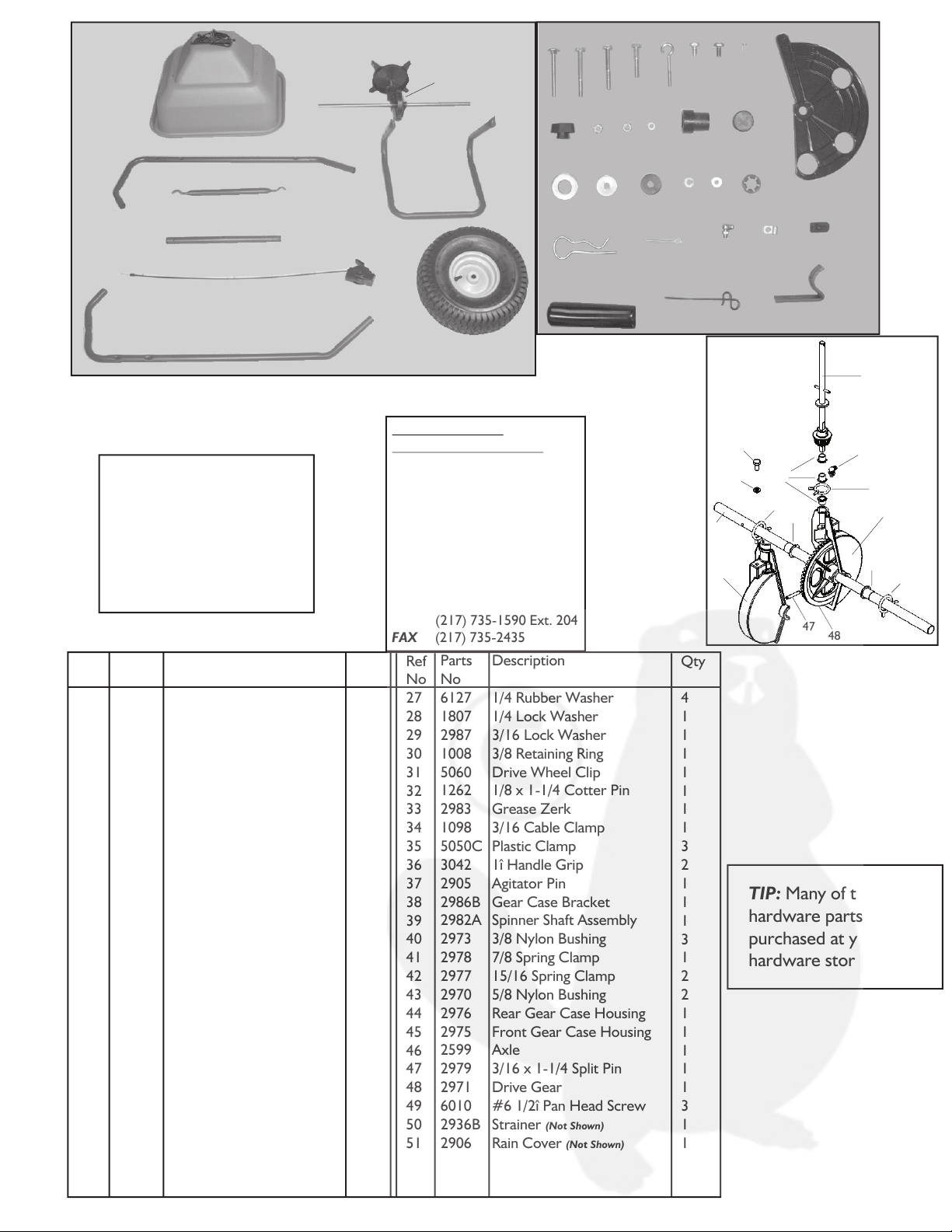
TIP: Many of these
hardware parts can be
purchased at your local
hardware store.
PLEASE DO NOT RETURN
THIS MERCHANDISE TO THE
STORE. CALL US AND WE
WILL TAKE CARE OF ANY
PROBLEM YOU MIGHT HAVE
WITH THIS PRODUCT.
Phone (800) 225 - 5891
EXT. #204
HOW TO ORDER
REPLACEMENT PARTS:
When ordering parts always
give model number, part
number and part description.
Send To:
FAX
Parts Division
316 Limit Street
Lincoln, IL 62656
(
(217) 735-2435
Phone (800) 225-5891
217) 735-1590 Ext. 204
Gear Case
Components
Qty
1
***
1
1
1
1
1
1
2
1
1
4
2
7
1
1
1
1
1
1
13
2
2
2
3
4
Ref
No
1
2
3
4
5
6
7
8
9
10
11
12
13
14
15
16
17
18
19
20
21
22
23
24
25
26
Parts
No
2969
INSET
2614
7127G
7124G
7156G
7126G
2441
2409
7125G
1868
2101
1086
6129
2985
1647
2984
1307
2828
1558
1270
3618
6214
3060
1646
6143
Description
Hopper
Gear Case Assembly
Spinner Disc
Left Hand Handle
Support Brace
Wrap Around Support
Cross Brace
Control Cable
Wheel
Right Hand Handle
1/4 x 2-1/4 Carriage Bolt
1/4 x 2-1/4 Hex Head Bolt
1/4 x 2 Hex Head Bolt
1/4 x 1-1/2 Hex Head Bolt
Eye Bolt
1/4 x 1/2 Hex Head Bolt
1/4 x 1/2 Hex Head Bolt FT
Slide Plate
1/4 Wing Nut
1/4 Lock Nut
1/4 Hex Nut
10-24 Hex Nut
5/8 Wheel Bushing
1î Tube Plug
5/8 Flat Washer
1/4 Fender Washer
Parts
No
6127
1807
2987
1008
5060
1262
2983
1098
5050C
3042
2905
2986B
2982A
2973
2978
2977
2970
2976
2975
2599
2979
2971
6010
2936B
2906
Description
1/4 Rubber Washer
1/4 Lock Washer
3/16 Lock Washer
3/8 Retaining Ring
Drive Wheel Clip
1/8 x 1-1/4 Cotter Pin
Grease Zerk
3/16 Cable Clamp
Plastic Clamp
1î Handle Grip
Agitator Pin
Gear Case Bracket
Spinner Shaft Assembly
3/8 Nylon Bushing
7/8 Spring Clamp
15/16 Spring Clamp
5/8 Nylon Bushing
Rear Gear Case Housing
Front Gear Case Housing
Axle
3/16 x 1-1/4 Split Pin
Drive Gear
#6 1/2î Pan Head Screw
Strainer
Rain Cover
(Not Shown)
(Not Shown)
Qty
4
1
1
1
1
1
1
1
3
2
1
1
1
3
1
2
2
1
1
1
1
1
3
1
1
Ref
No
27
28
29
30
31
32
33
34
35
36
37
38
39
40
41
42
43
44
45
46
47
48
49
50
51
1
2
3
4
5
6
7
8
9
10
11 12 13 14 15 16 17 18
19 20 21 22 23 24
25 26 27 28 29 30
31 32
33 34 35
36 37 38
39
33
41
44
43
42
40
42
43
17
28
46
45
47 48
49
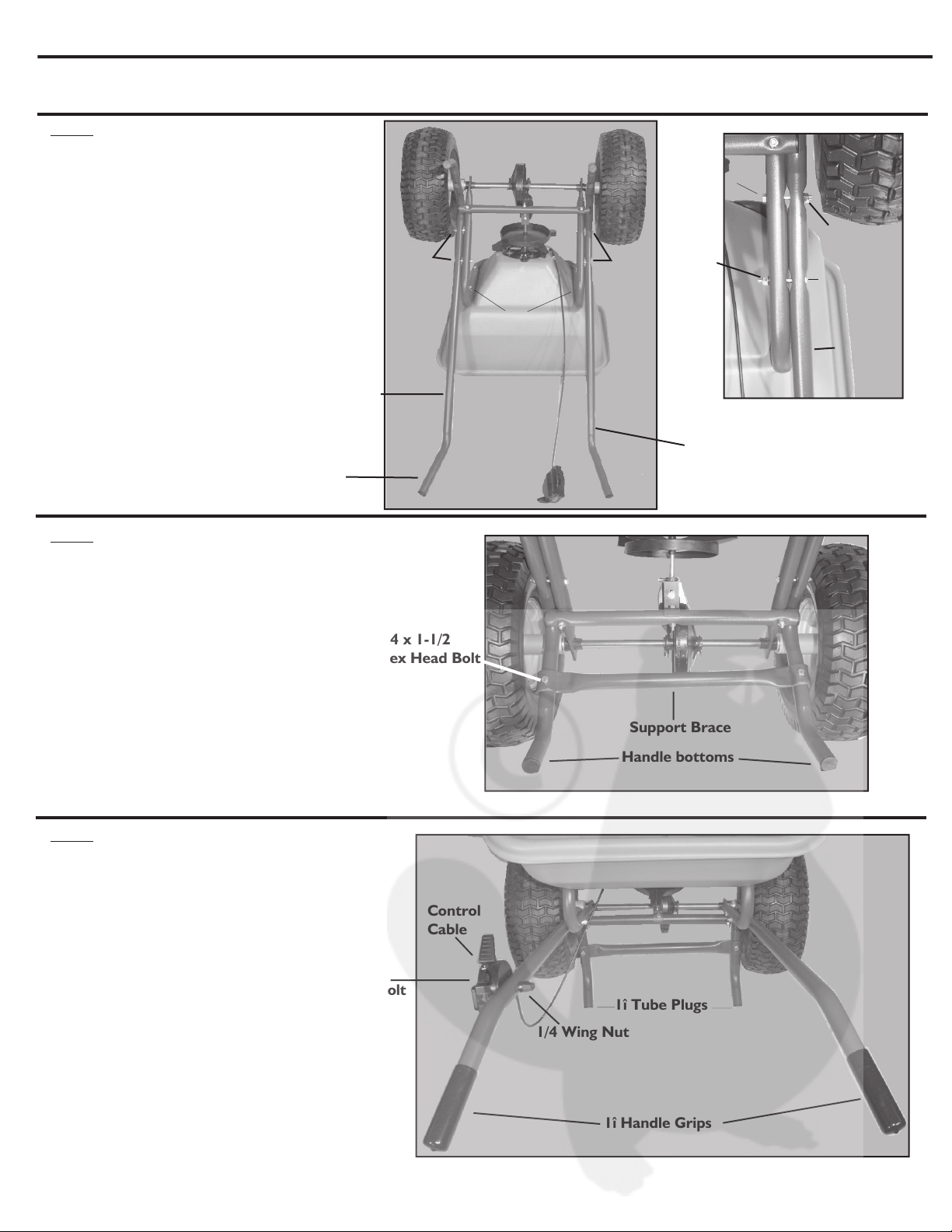
ASSEMBLY INSTRUCTIONS FOR THE SB6000RD
ASSEMBLY TIP: Loosely tighten nuts and bolts at first. Fully tighten when the spreader is
completely assembled.
Step 1
Attach both the Right Hand Handle (10) and the
Left Hand Handle (4) to the outside of the Wrap
Around Support (6) using 1/4 x 2-1/4 Hex Head
Bolts (12) and 1/4 Hex Head Nuts (21). The top
bolts will go from the outside-in, and the bottom
bolts will go from inside-out (see blown-up view).
Step 2
Attach the Support Brace (5) to the
bottom of the Right Hand Handle (10) and
the Left Hand Handle (4) using
1/4 x 1-1/2 Hex Head Bolts (14) and
1/4 Hex Head Nuts (21).
Step 3
Attach the Control Cable (8) to the outside
of the Left Hand Handle (4) using a 1/4 x 2-1/4
Carriage Bolt (11) and a 1/4 Wing Nut (19).
Insert the 1î Tube Plugs (24) inside the opening
of both handle bottoms. Place the 1î Handle
Grips (36) over both handle tops.
Step 4
To ensure proper function of the gear
case, make sure the Spinner Shaft is
perpendicular to the bottom of the
Hopper. Adjustments can be made
with the Eye Bolt that connects
the Gear Case Bracket to the
Gear Case Housing.
This unit is warranted against defects in materials and workmanship to the
original purchaser, under normal use and service, for a period of ninety (90)
days from date of sale. During the Warranty Period, we will repair or replace
at our option free of charge to the original purchaser, any part of the Unit
that our examination shows to be defective in workmanship or materials.
This Warranty apply to damage caused by transit, misuse, abuse,
neglect, accident, normal wear, or alterations by unauthorized persons.
LIMITED WARRANTY
Does Not
MAINTENANCE INSTRUCTIONS
Numbered Settings
Control Lever
Calibration
Indicator button
ON -- Push the Control Lever
forward until it stops
against Calibration Button.
OFF -- Pull Control Lever back
until it stops.
USING YOUR SPREADERS CONTROLLER
Settings are made by pushing down on the Calibration Indicator
button and setting to the desired number on the Control Cable
assembly.
SEE APPLICATION CHART FOR SETTING INFORMATION.
Recommended operating weight ñ 120 lbs.
1. Always have the control lever in OFF position
before filling the hopper.
2. Always push the spreader forward to operate;
do not pull backwards.
3. Start moving forward before pushing the control
lever to the ON position. Pull the control lever to
OFF position before stopping or turning.
.
DO NOT allow spreader to sit stationary with
material in the hopper and control lever in the
ON position.
4. Push the spreader at a steady speed.
5. To avoid misses or striping, space each pass across the
lawn so approximately 20% of the spread width overlaps
onto the previous pass. This provides a ìfeatheredî over-
lap to even out distribution over the width of the spread.
CAUTION: care must be taken with any weed killer,
pesticide, or combination product. They can be harmful
to other plant life in the yard.
BROADCAST SPREADER OPERATION
1. Empty hopper after each use. Do not store spreader
with material left in hopper.
2. Wash spreader thoroughly and wipe dry.
3. Lubricate all moving parts. Use a grease gun to apply
grease to the gearbox assembly.
Apply oil to spinner shaft
(including area shaft extends through hopper), slide
plate and where the spinner shaft and axle extend
through the gearbox.
CAUTION: Use a
reasonable amount of grease. DO NOT pack
gearbox full of grease.
1/4 x 1-1/2
Hex Head Bolt
Gear Case
Bracket
Eye Bolt
Handle ends will face
outward when assembled
properly.
Right Hand Handle
Left Hand Handle
Bolts Bolts
Wrap Around
Support
1/4 x 2-1/4
Hex Head Bolt
1/4 Hex
Head Nut
1/4 Hex
Head Nut
1/4 x 2-1/4
Hex Head Bolt
Left Hand
Handle
1î Handle Grips
1î Tube Plugs
Control
Cable
1/4 x 2-1/4
Carriage Bolt
1/4 Wing Nut
Support Brace
1/4 x 1-1/2
Hex Head Bolt
Handle bottoms
SB6000RD
Broadcast Spreader
12/02
Assembly Instructions & Parts List
2996
MADE IN
USA
PRECISION PRODUCTS, INC.
TIP: Many of these
hardware parts can be
purchased at your local
hardware store.
PLEASE DO NOT RETURN
THIS MERCHANDISE TO THE
STORE. CALL US AND WE
WILL TAKE CARE OF ANY
PROBLEM YOU MIGHT HAVE
WITH THIS PRODUCT.
Phone (800) 225 - 5891
EXT. #204
HOW TO ORDER
REPLACEMENT PARTS:
When ordering parts always
give model number, part
number and part description.
Send To:
FAX
Parts Division
316 Limit Street
Lincoln, IL 62656
(
(217) 735-2435
Phone (800) 225-5891
217) 735-1590 Ext. 204
Gear Case
Components
Qty
1
***
1
1
1
1
1
1
2
1
1
4
2
7
1
1
1
1
1
1
13
2
2
2
3
4
Ref
No
1
2
3
4
5
6
7
8
9
10
11
12
13
14
15
16
17
18
19
20
21
22
23
24
25
26
Parts
No
2969
INSET
2614
7127G
7124G
7156G
7126G
2441
2409
7125G
1868
2101
1086
6129
2985
1647
2984
1307
2828
1558
1270
3618
6214
3060
1646
6143
Description
Hopper
Gear Case Assembly
Spinner Disc
Left Hand Handle
Support Brace
Wrap Around Support
Cross Brace
Control Cable
Wheel
Right Hand Handle
1/4 x 2-1/4 Carriage Bolt
1/4 x 2-1/4 Hex Head Bolt
1/4 x 2 Hex Head Bolt
1/4 x 1-1/2 Hex Head Bolt
Eye Bolt
1/4 x 1/2 Hex Head Bolt
1/4 x 1/2 Hex Head Bolt FT
Slide Plate
1/4 Wing Nut
1/4 Lock Nut
1/4 Hex Nut
10-24 Hex Nut
5/8 Wheel Bushing
1î Tube Plug
5/8 Flat Washer
1/4 Fender Washer
Parts
No
6127
1807
2987
1008
5060
1262
2983
1098
5050C
3042
2905
2986B
2982A
2973
2978
2977
2970
2976
2975
2599
2979
2971
6010
2936B
2906
Description
1/4 Rubber Washer
1/4 Lock Washer
3/16 Lock Washer
3/8 Retaining Ring
Drive Wheel Clip
1/8 x 1-1/4 Cotter Pin
Grease Zerk
3/16 Cable Clamp
Plastic Clamp
1î Handle Grip
Agitator Pin
Gear Case Bracket
Spinner Shaft Assembly
3/8 Nylon Bushing
7/8 Spring Clamp
15/16 Spring Clamp
5/8 Nylon Bushing
Rear Gear Case Housing
Front Gear Case Housing
Axle
3/16 x 1-1/4 Split Pin
Drive Gear
#6 1/2î Pan Head Screw
Strainer
Rain Cover
(Not Shown)
(Not Shown)
Qty
4
1
1
1
1
1
1
1
3
2
1
1
1
3
1
2
2
1
1
1
1
1
3
1
1
Ref
No
27
28
29
30
31
32
33
34
35
36
37
38
39
40
41
42
43
44
45
46
47
48
49
50
51
1
2
3
4
5
6
7
8
9
10
11 12 13 14 15 16 17 18
19 20 21 22 23 24
25 26 27 28 29 30
31 32
33 34 35
36 37 38
39
33
41
44
43
42
40
42
43
17
28
46
45
47 48
49
Other Precision Products Spreader manuals


Popular Spreader manuals by other brands


New Leader
New Leader NL4500G4 Operator's manual

Sealey
Sealey SPB57T instruction manual

The Handy
The Handy THDS Operator's manual and parts list

Farm Fans
Farm Fans SCATTERGRAIN FFD-3000VS Installation and operation manual

Trynex
Trynex TurfEx TS85SS Owner's/operator's manual

The Handy
The Handy THS80 Assembly and operating instructions