manuals.online logo
Brands
  1. Home
  2. •
  3. Brands
  4. •
  5. Ampac
  6. •
  7. Fire Alarm
  8. •
  9. Ampac 4310-0086 User manual

Ampac 4310-0086 User manual

Other Ampac Fire Alarm manuals

Ampac ZoneSense Plus Guide

Ampac

Ampac ZoneSense Plus Guide

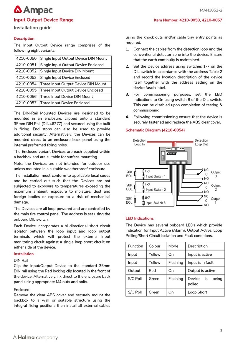
Ampac 4210-0050 User manual

Ampac

Ampac 4210-0050 User manual

Ampac Warning Sign 4210-011 User manual

Ampac

Ampac Warning Sign 4210-011 User manual

Ampac XP95 User manual

Ampac

Ampac XP95 User manual

Ampac SmartTerminal Guide

Ampac

Ampac SmartTerminal Guide

Ampac XP95 User manual

Ampac

Ampac XP95 User manual

Ampac ZoneSense User manual

Ampac

Ampac ZoneSense User manual

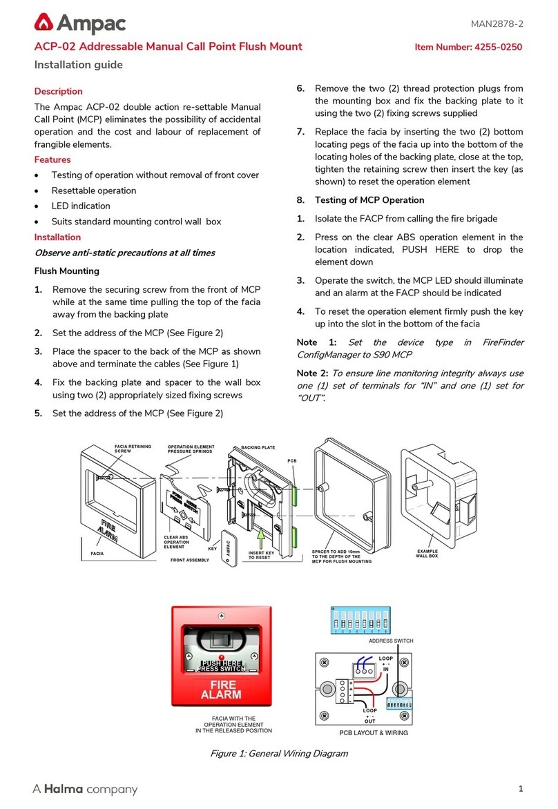
Ampac ACP-02 User manual

Ampac

Ampac ACP-02 User manual

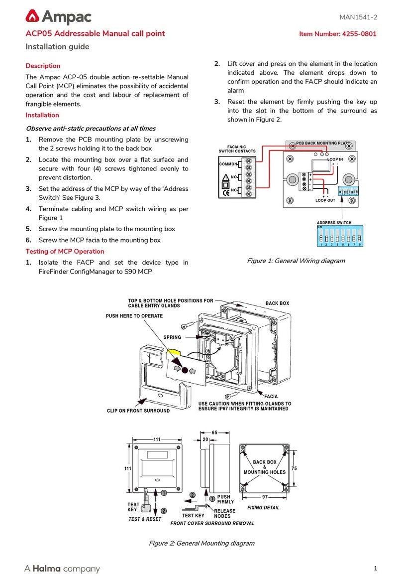
Ampac ACP05 User manual

Ampac

Ampac ACP05 User manual

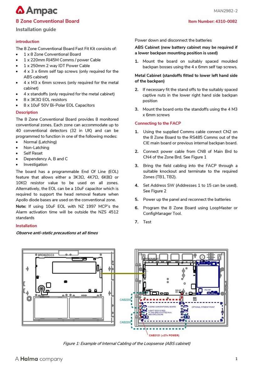
Ampac 4310-0082 User manual

Ampac

Ampac 4310-0082 User manual

Ampac ACP-02 User manual

Ampac

Ampac ACP-02 User manual

Ampac ZoneSenseDH4 Guide

Ampac

Ampac ZoneSenseDH4 Guide

Ampac FireFinder II Series User manual

Ampac

Ampac FireFinder II Series User manual

Ampac FireFinder PLUS Guide

Ampac

Ampac FireFinder PLUS Guide

Ampac NZ 100 User manual

Ampac

Ampac NZ 100 User manual

Ampac FireFinder NZS 4512 User manual

Ampac

Ampac FireFinder NZS 4512 User manual

Ampac FireFinder PLUS Guide

Ampac

Ampac FireFinder PLUS Guide

Ampac MAN 3038 User manual

Ampac

Ampac MAN 3038 User manual

Ampac Apartment Module User manual

Ampac

Ampac Apartment Module User manual

Ampac ZoneSense Plus Guide

Ampac

Ampac ZoneSense Plus Guide

Ampac ZoneSense PLUS Agent Release Guide

Ampac

Ampac ZoneSense PLUS Agent Release Guide

Popular Fire Alarm manuals by other brands

Simplex 4010ES Quick reference guide

Simplex

Simplex 4010ES Quick reference guide

Global Fire Equipment VALKYRIE AS manual

Global Fire Equipment

Global Fire Equipment VALKYRIE AS manual

Zeta Alarm Systems INFINITY ID2 installation manual

Zeta Alarm Systems

Zeta Alarm Systems INFINITY ID2 installation manual

System Sensor 22051TLE-RF-26 Installation and maintenance instructions

System Sensor

System Sensor 22051TLE-RF-26 Installation and maintenance instructions

Pittway Notifier AM2020 troubleshooting guide

Pittway

Pittway Notifier AM2020 troubleshooting guide

Kidde VM-1 Technical reference manual

Kidde

Kidde VM-1 Technical reference manual

LST SIM016-3 Specification sheet

LST

LST SIM016-3 Specification sheet

Fireboy- Xintex FBD-MZ Owner's Manual & Installation Instructions

Fireboy- Xintex

Fireboy- Xintex FBD-MZ Owner's Manual & Installation Instructions

GST DI-9204 Installation

GST

GST DI-9204 Installation

Fire-Lite Alarms MS-2 instructions

Fire-Lite Alarms

Fire-Lite Alarms MS-2 instructions

hyfire HY5000 Series install guide

hyfire

hyfire HY5000 Series install guide

Radionics Radionics 9124 user guide

Radionics

Radionics Radionics 9124 user guide

UniPOS FD 7120 instruction manual

UniPOS

UniPOS FD 7120 instruction manual

Teletek electronics SensoMAG MRB50 installation instructions

Teletek electronics

Teletek electronics SensoMAG MRB50 installation instructions

bolid S2000-IP-03 instruction manual

bolid

bolid S2000-IP-03 instruction manual

FIREGUARD GLOBAL FG-S01_AP quick start guide

FIREGUARD GLOBAL

FIREGUARD GLOBAL FG-S01_AP quick start guide

Panasonic MEW01091 operating instructions

Panasonic

Panasonic MEW01091 operating instructions

Notifier UZC-256 installation manual

Notifier

Notifier UZC-256 installation manual

manuals.online logo
manuals.online logoBrands
  • About & Mission
  • Contact us
  • Privacy Policy
  • Terms and Conditions

Copyright 2025 Manuals.Online. All Rights Reserved.

MAN3014-1
32 Zone Indicator Module Item Number: 4310-0086
Installation guide
1
Introduction
The 32 Zone Indicator Module Kit consists of:
•1 x BRD43ZAMC’x’-A
•1 x DEC1515-T2
•1 x ENC1824-A
•1 x ENC1825-A
•4 x LAB1516
•1 x CAB1905 RJ45 Cable
Description
The 32 Zone Indicator card has 32 bi-coloured LED’s
which can be used to display the status of up to 32
Zones.
The zone numbers assigned to each LED are
configurable and the LED’s will operate in the following
manner for the respective zone statuses:
ZONE STATUS
LED STATE
LED COLOUR
FIRE
ON STEADY
RED
DEPENDENCY B
FLASH
RED
DISABLED
ON STEADY
YELLOW
FAULT
FLASH
YELLOW
ALL OTHER
OFF
n/a
The card will also respond to a lamp test when
instigated on the panel to which it is connected.
Installation
Observe anti-static precautions at all times
1. Power down and disconnect the batteries
Mounting
2. The module should already be mounted to
ENC1824-A / ENC1825-A. (Figure 2)
3. Mount the module in the next free ancillary cutout
at the Fire Alarm Control Panel.
Connecting to the FACP
4. Set the required Address for the 32 Zone Indicator
card using the 4 way dip switch (Figure 3)
5. If fitted as the last module the EOL link needs to be
fitted (Figure 3)
6. Using the supplied RJ45 cable connect the 32
Zone Indicator card to the applicable Fire Alarm
Control Panel (FACP) (see Figure 4 & 5 overleaf)
7. Power up the panel and reconnect the batteries
8. Using the applicable Configuration tool
ConfigManager (FireFinder Plus) or LoopMaster
(LoopSense) configure the 32 ZAMC board
9. Test
Figure 1: DEC1515-T2
Panel & PCB Securing Tabs
PCB
Clear Plastic Clip In Label Holder
Clip On Plastic Surround
( Remove to Insert Labels )
To Remove Push Down
Here and Lift Upwards
Connectors
Figure 2: 32 Zone Mimic ENC1824-A / ENC1825-A
Mounting
Fit EOLTermination Link
if Last Module
on Comms Bus
1 2 3 4
ON
Top Card &
PCB Securing Clips
Bottom Card &
PCB Securing Clips
In Out
Address
Switch
Set to 1
C
N
1
C
N
2
RS485 Control
/ 27VDC
Comms In
RS485 Control
/ 27VDC
Comms Out
Figure 3: Rear View 32 Zone Alarm Mimic Card
MAN3014-1
32 Zone Indicator Module Item Number: 4310-0086
Installation guide
2
OUT
BUZZER
INHIBIT
BUZZER
RS485 EOL
+5V
0V
PRINTER 27V
TERMINATION BOARD
1
NODE ADDRESS NETWORK LOOP
COMMS
PSU MONITOR
PRINTER
RESET
27V IN
COMMS1
RS232/MODEM
(BOTTOM) EXPANSION PANEL EXPANSION LEDS FRONT PANEL
BRIGADE I/F
23
4
BACKLIGHT
EXPANSION
EXTRA CONTROLS
KEY SWITCH
EXPANSION
SLAVE 2
SLAVE 3
SLAVE 4
MODULE
MODULE
COMMS2 RS232 (TOP)
RS232
COMMS 2
CN26
CN8
CN27
CN11
CN23
CN17
CN13 CN15
CN10
CN4
87654321
SW2
CN18
CN14
CN9
CN16
CN7
CN2 CN5
+
BZ1
SW1
CN3 CN1
LK3
CN20
LK2
CN6
CN100
DEBUG
CN2
LK1
TP1
DEBUG
CN2
LK1
TP1
DEBUG
CN2
LK1
TP1
MAIN BOARD
MAIN CPU
SLAVE CPU 4 SLAVE CPU 3 SLAVE CPU 2
CN21
USB
CN25
Fit EOL Termination Link
if Last Module
on Comms Bus
In Out
Address Switch
Set to Appropriate
Address
(Add 1 Shown)
1 2 3 4
ON
C
N
1
C
N
2
RS485 Control
/ 27VDC
Comms In
RS485 Control
/ 27VDC
Comms Out
C
N
21
Fit EOL Termination Link
if Last Module
on Comms Bus
In Out
Address Switch
Set to Appropriate
Address
(Add 1 Shown)
1 2 3 4
ON
C
N
1
C
N
2
RS485 Control
/ 27VDC
Comms In
RS485 Control
/ 27VDC
Comms Out
CAB1905
CAB1905
Figure 4: General Wiring 32 Zone Alarm Mimic Card (FireFinder Plus)
USB
N1236
MON. OU T1
0V
AUX OUT1
3
2
1
OUT2
OUT1
+VE
EARTH MON.
COMMS
SGD
BRD82MBA6-
+VE +VEA+
0V+27V
INPUTS SUPERVISED O/PS
LOOP 1 LOOP 2
B-RS485+ RS485- SHD 2+ 3+ 4+COM 1+ 2+ AUX OUT2
2- 3- 4-3+1+ 4+1-
ETH
+27V 0V
PWR OUT
PSU CONTROL
DIAGNOSTICS
RS485
TERM
LOAD
RESET
HLI PORT
FRONT
CONTROLS
PWR IN
N/O CN/C N/O CN/C N/O CN/C
RELAY 1 RELAY 2 RELAY 3
COMMS A- B+ B+A- B-A+
DONGLE
31/07/2009
1
2
3
DIAGNOSTICS
RS232
40V
12V5V
3V3
0V
0V
CN11
TB1 TB6
K1
CN6
CN1
CN7
CN4
CN5
CN10
CN2
CN8
TB4TB2 TB5TB3
SW1
CN9
K3
U24
CN3
MON. OU T4MON. OU T3MON. OU T2
D12
D11D10
D9
TB1 TB2 TB3 TB4 TB5
CN2
CN4
CN11
CN6 CN7 CN8 CN9
CN5
TB6
Fit EOL Termination Link
if Last Module
on Comms Bus
In Out
Address Switch
Set to Appropriate
Address
(Add 1 Shown)
1 2 3 4
ON
C
N
1
C
N
2
RS485 Control
/ 27VDC
Comms In
RS485 Control
/ 27VDC
Comms Out
Fit EOL Termination Link
if Last Module
on Comms Bus
In Out
Address Switch
Set to Appropriate
Address
(Add 1 Shown)
1 2 3 4
ON
C
N
1
C
N
2
RS485 Control
/ 27VDC
Comms In
RS485 Control
/ 27VDC
Comms Out
CAB1905
C
N
10
CAB1905
Figure 5: General Wiring 32 Zone Alarm Mimic Card (LoopSense)