Ampcontrol BAT7001 User manual

BAT7001 V2 - Power Supply
Manufactured in Australia by Ampcontrol
CSM Pty Ltd ACN 000 915 542
P: (02) 4903 4800
F: (02) 4903 4888
E: Electronics@ampcontrolgroup.com
W: Ampcontrolgroup.com
No copies of the information or drawings
within this manual shall be made without
the prior consent of Ampcontrol.
USER MANUAL

BAT7001 Version 2 - USER MANUAL
Copyright Notice
No part of this publication may be
reproduced, transmitted or transcribed
into any language by any means
without the express written permission
of Ampcontrol Pty Ltd, 7 Billbrooke
Close Cameron Park, NSW 2285,
Australia.
Disclaimer
Ampcontrol Pty Ltd will make no
warranties as to the contents of this
documentation and specifically
disclaims any implied warranties or
fitness for any particular purpose.
Ampcontrol further reserves the right to
alter the specification of the system
and/or manual without obligation to
notify any person or organisation of
these changes.
Before You Begin
We would like to take a moment to
thank you for purchasing the BAT7001
“Fault” driven Power Supply. To
become completely familiar with this
equipment and to ensure correct
operation, we recommend that you take
the time to read this user manual
thoroughly.
CRN: 10152
CONTENTS
1. Application.................................1
2. Description................................. 1
2.1 LED Indication.........................2
3. Commissioning.........................3
4. Equipment List......................... 3
5. Specifications............................ 3
6. Drawings
RELE002
BAT7001 Schematic Diagram.......4
RELA010
Case Dimensions............................ 5

BAT7001 Version 2 USER MANUAL ISSUE 1
-1-
1. Application
A source of auxiliary power is generally
required in circuit breaker applications in
order to:
1. Provide power to close and trip coils.
2. To allow protective relays to operate
reliably.
In certain applications it may be
uneconomic (remote installations) or
contrary to safety regulations (eg.
underground coal mines) to use a battery to
provide auxiliary power.
It is not recommended to derive auxiliary
power directly from the local AC supply.
Under fault conditions this voltage may
instantaneously fall to a level below which
either the circuit breaker shunt trip coil or
the protective relay may not operate
correctly.
The BAT7001 Power Supply is designed
to overcome these problems.
Under normal load conditions it uses the
upstream voltage source to charge storage
capacitors.
Under remote fault conditions the local
voltage will be depressed, but the current
can be expected to be greater than the rated
current. This current is used by the
BAT7001 Power Supply to supplement the
available input voltage and so keep the
capacitors charged.
For three phase faults in close proximity to
the substation the substation bus voltage
can fall to zero, however the current
present at the BAT7001 Power Supply’s
inputs will be several multiples of rated
current and is used to ensure that the
capacitors remain fully charged.
It is not generally recommended to use the
BAT7001 Power Supply without the
presence of upstream voltage transformers.
This is due to the fact that the BAT7001
Power Supply would not be charged up at
the instant that the circuit breaker is closed.
If a "switch on to fault" condition occurs,
without the BAT7001 Power Supply being
supplied from an upstream VT, the
available fault current would charge up the
BAT7001 Power Supply, but only after a
finite time period. This additional time
delay in tripping the circuit may not be
acceptable and is eliminated by the
connection to an upstream voltage
transformer.
Where applications without upstream
voltage transformers are implemented the
use of transistorised protective relays
rather than microprocessor relays is
preferred. This is because microprocessor
relays generally undergo a start up routine
upon power up and this may last several
seconds.
2. Description
The BAT7001 Power Supply is designed
to supply a DC voltage for the tripping of
circuit breakers and/or power other
protection devices.
The DC voltage is derived from a 110
VAC supply and three 1 or 5 amp Current

BAT7001 Version 2 USER MANUAL ISSUE 1
-2-
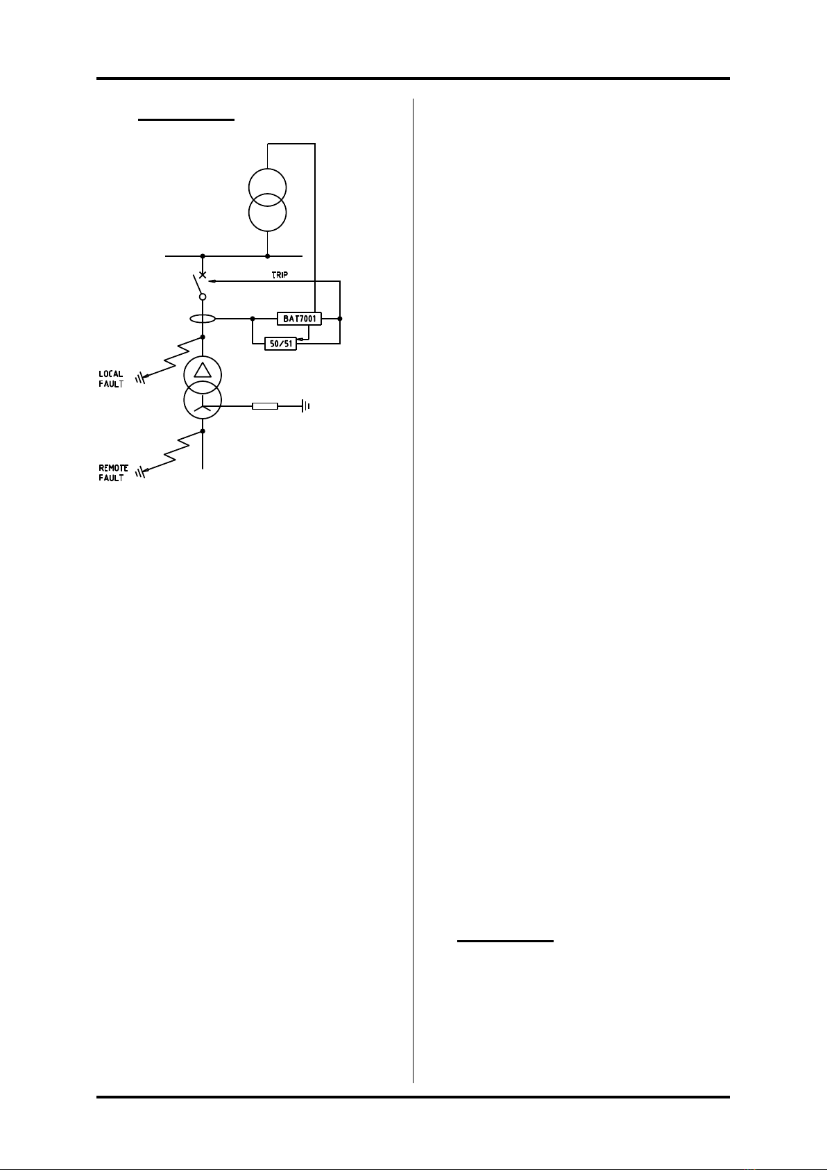
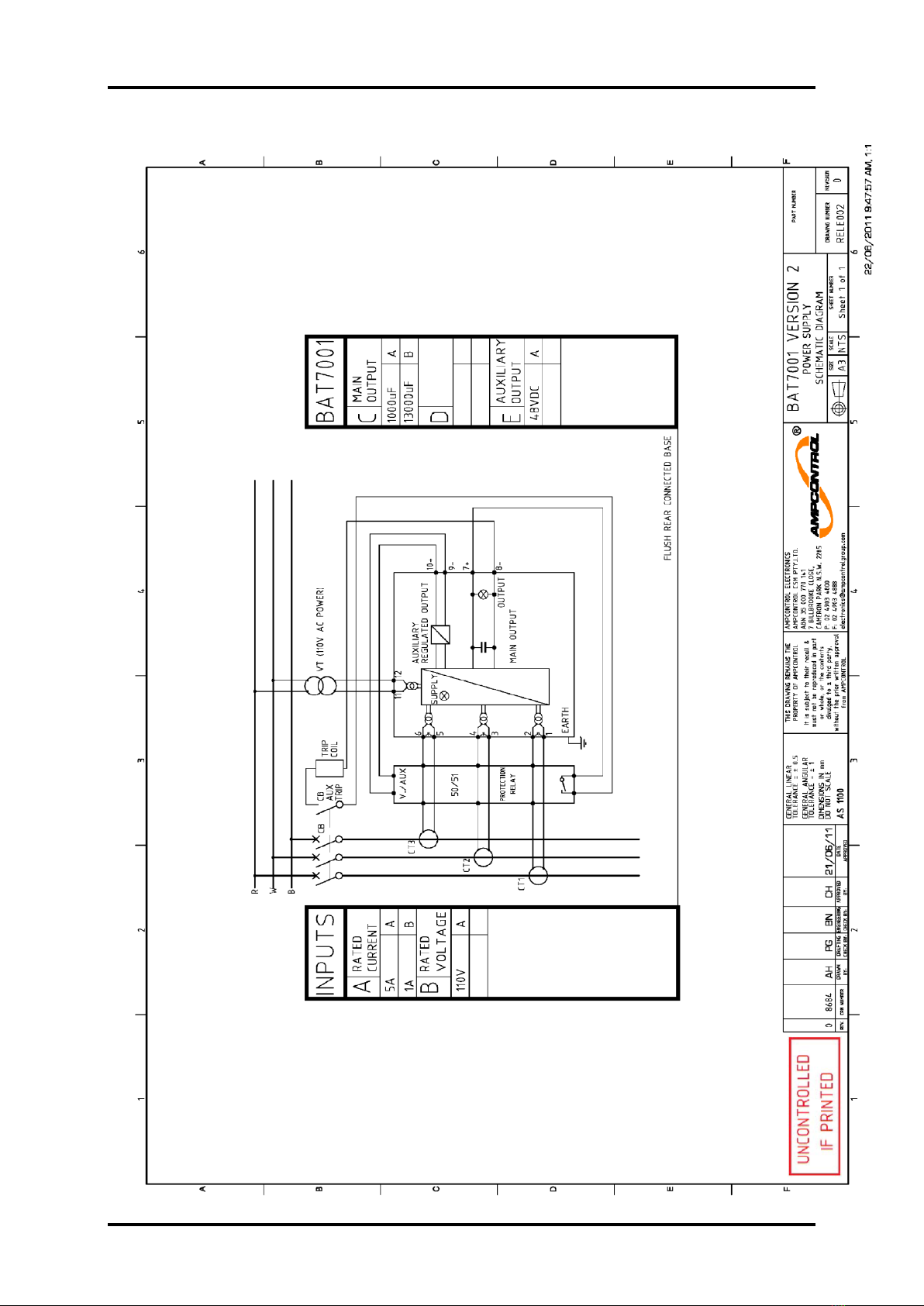
Transformers (to be specified) being used
for protection purposes. See Schematic
Drawing RELE002, Page 4.
The BAT7001 Power Supply provides two
independent DC supplies. The main supply
is 48VDC unregulated and is used for the
trip supply of a circuit breaker. The
auxiliary supply is a regulated 48VDC,
400mA supply and is suitable for the
supply of protection relays.
The BAT7001 Power Supply is available
in 1A or 5A units to suit the type of current
transformer used in the installation.
The main output supply is automatically
disconnected when the output voltage falls
below an internally preset level of 25 volts
and is restored when the voltage rises to
the second internally preset level of 48
volts. In the event that the circuit
breaker does not open successfully on
the first discharge the BAT7001 Power
Supply automatically recharges and re-
applies the trip supply to the circuit
breaker until it opens.
To enable the unit to be used in hazardous
locations (such as underground coal mines)
the output voltage is guaranteed to self
discharge (even when no load is connected
to the supply) following the removal of
power from the unit. The output voltage
typically falls to less than 3 volts after 2
minutes and less than 0.5 Volts after 4
minutes.
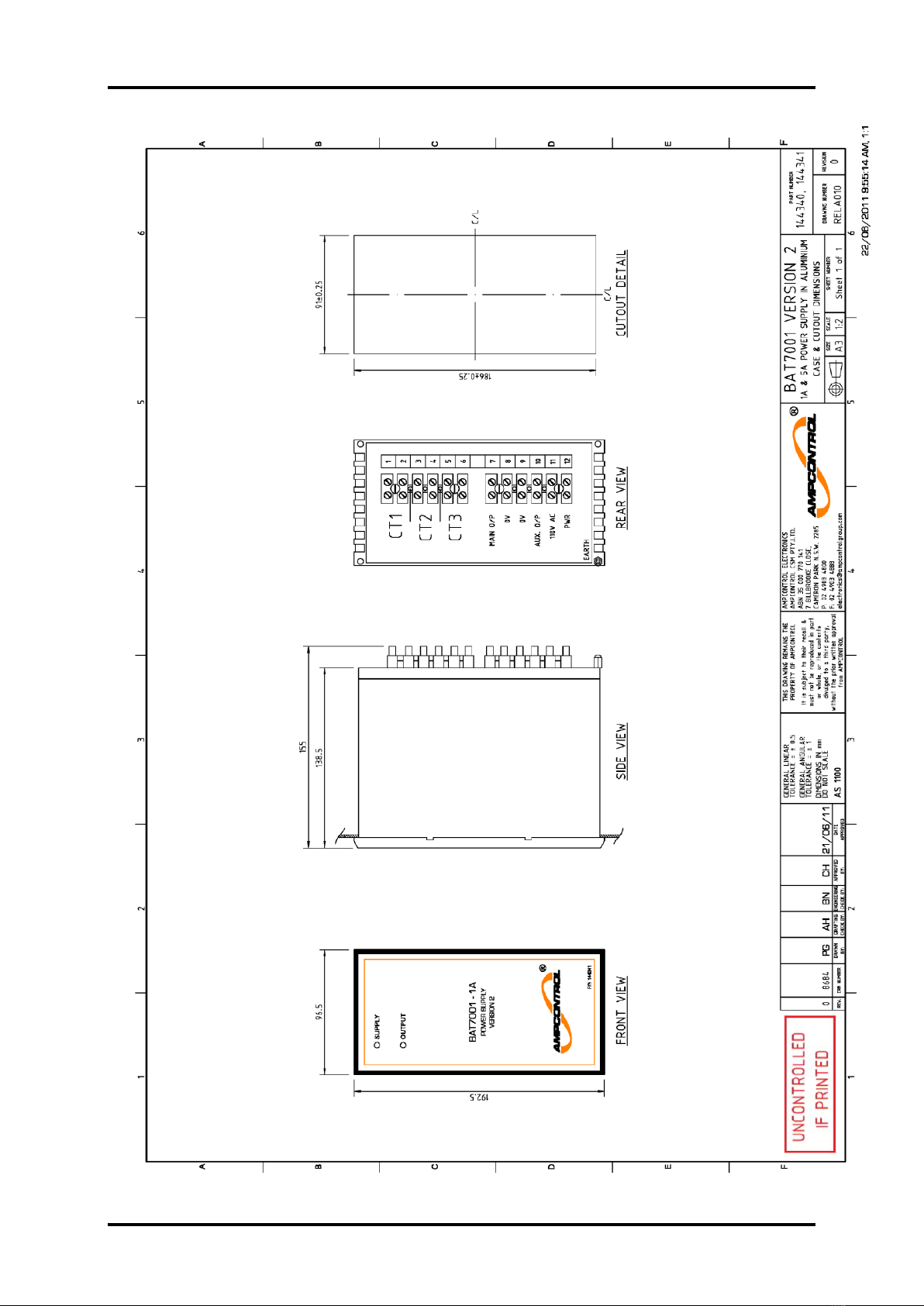
The BAT7001 Power Supply is housed in
a standard aluminium flush mounted case
(see Drawing RELA010, Page 5 for case
details).
2.1 LED Indication
There are two LEDs mounted on the front
plate.
Supply –green LED which flashes when
an input is present (voltage or current or
both).
Output –red LED that flashes when the
main output DC voltage is healthy.
3. Commissioning
The following steps must be followed to
ensure the correct operation of the BAT
7001 Power Supply:
1. It is essential that the electric circuit to
the circuit breaker trip coil is wired
through a normally open (N/O) circuit
breaker auxiliary contact. This will
ensure that the trip circuit is broken as
the circuit breaker opens and therefore
prevent the BAT 7001 Power Supply
from attempting unnecessary re-strikes
on the trip coil.
Breaking the trip circuit with the
auxiliary contact is the usual practice
however it is essential in the case
where the protection relay latches its
output tripping contact.
2. Check the 110VAC supply on
terminals 11 and 12.
3. Insert the BAT 7001 Power Supply
into the panel and tighten the slotted
holding screws.
4. Apply power and check that the output
voltage between terminals 7 (+ve) and
8 (-ve) is approximately 50VDC.
Check that the output voltage between
terminals 10 (+ve) and 9 (-ve) is 48V
DC.
5. Simulate a trip condition by operating
the protection relay or by bridging its
output tripping contact. The circuit
breaker should trip immediately.

BAT7001 Version 2 USER MANUAL ISSUE 1
-3-
4. Equipment List
144341 BAT7001 Version 2 - 1A Power Supply
144340 BAT7001 Version 2 - 5A Power Supply
144344 BAT7001 Version 2 - Power Supply User Manual
5. Specifications
Inputs
Rated Current In = 5A
20VA burden at rated current
In = 1A
20VA burden at rated current
Rated Voltage Vn = 110 VAC
Burden 20VA at rated voltage (Iac = 0)
CT Requirements In = 5A, 10P25F20
In = 1A, 10P50F20
(not including overcurrent/earth fault relays and wiring impedances)
Example of Designation System
10 P 50 F20
Where: 10 = 10% Composite Error
P = Class
50 = Secondary Voltage
F20 = Accuracy Limit Factor
Outputs
Main Voltage Range 48VDC
13000 microfarad capacitor
Auxiliary 48VDC, 400mA
Typical Trip < 300 watts
Coil Burden
Discharge Time
<3V after 2 minutes, <0.5V after 4 minutes
LED Indication
Supply Green LED flashes when input is present
Output Red LED flashes when main voltage output is healthy

BAT7001 Version 2 USER MANUAL ISSUE 1
-4-

BAT7001 Version 2 USER MANUAL ISSUE 1
-5-
Table of contents
Other Ampcontrol Power Supply manuals