1
Amphenol Network Solutions
All rights reserved. 12.16.19 138661-5 A0
509.926.6000 – amphenol-ns.com
Breaker/TFD Distribution
Panel with 5 GMTs
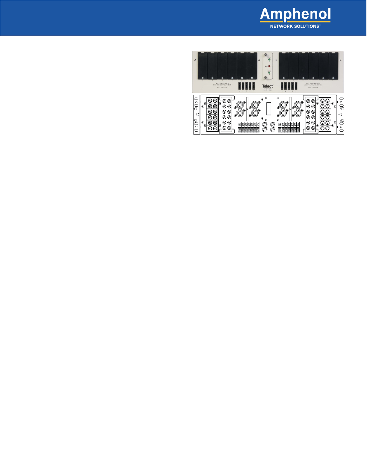
1.1 Overview
The Amphenol Network Solutions dual-feed 350A circuit
breaker/TFD panel provides high-capacity protection for
secondary power distribution, co-locations and data for
communications equipment. In addition, the provided GMT
fuses enhance power distribution for applications that require
15A or less. Each of the dual feeds contains six interrupter
positions for either bullet-style REC switch (ON/OFF) circuit
breakers or TFD holders. Each feed also includes five GMT
fuses. Go to amphenol-ns.com to order circuit breakers, TFD
holders and GMT fuses:
•TLS fuses up to 70A rated, continuous current 80% of rated
•TPS fuses up to 125A rated, continuous current 80% of rated
•GMT fuses up to 15A rated, continuous current 70% of rated
•Circuit breakers up to 100A rated, continuous current 80% of rated
This panel ships with solid covers over the circuit breaker/TFD positions and with fuse-slot fillers in the GMT holders.
Sides A and B are electrically isolated except for the replaceable alarm card, which contains power and alarm LEDs. The
panel features separate power status LEDs and a single-alarm LED for breaker trips or fuse failures. Power and alarm
relay connections are controlled on-board and provide dry Form-C contacts.
All input, output and alarm terminals are on the rear, and all are covered by a single, full-size transparent terminal cover.
Separate input terminal sub-covers maintain protection for the other terminals when you are only working with the load
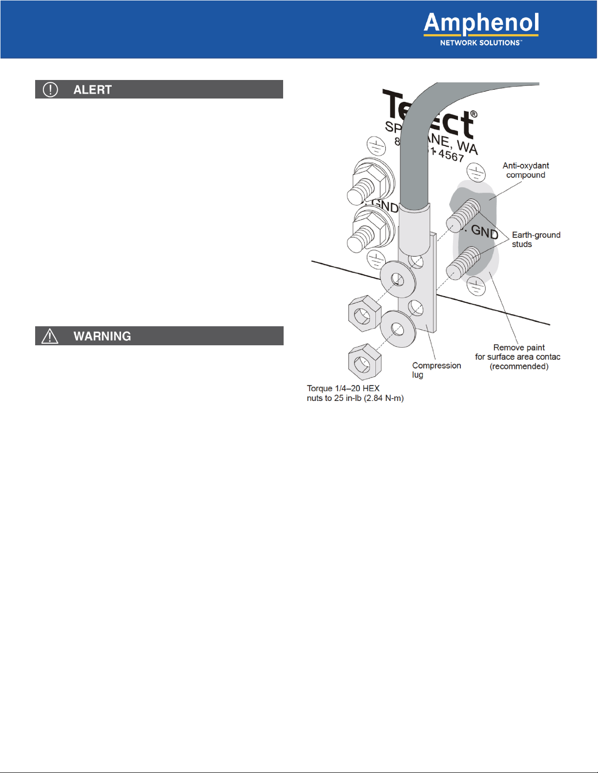
and/or alarm terminals. Two pairs of ground studs on the rear panel provide flexibility in grounding from either side of the
rack. The input, output and ground studs support the following cable gauges:
•Input terminals support up to a 750-MCM cable
•Output terminals support up to a 2-AWG cable
•Ground studs support up to a 1-AWG cable
Fig. 1: 350CB06 Distribution Panel