manuals.online logo
Brands
  1. Home
  2. •
  3. Brands
  4. •
  5. ETI
  6. •
  7. Circuit Breaker
  8. •
  9. ETI EFI-4B User manual

ETI EFI-4B User manual

Navodilo za montažo in uporabo
TOKOVNO ZAŠČITNO STIKALO EFI-4B IN B+
1. MONTAŽA
Tokovno zaščitno stikalo se lahko uporablja v TN-S, TN-C-S,
TT in IT sistemih omrežja, torej povsod tam, kjer zaščitni in
nevtralni vodnik nista povezana.
Tokovno zaščitno stikalo je namenjeno montaži na nosilno letev
35 mm EN50022.
2. PRIKLJUČEVANJE
6 4 2 N
| | | |
5 3 1 N
Dovod je lahko zgoraj ali spodaj.
3. NAJVEČJA VREDNOST PREDVAROVALKE
Za nazivne tokove do 63 A se uporabljajo talilni vložki s
karakteristiko gL- gG z nazivnim tokom 63 A.
4. MAKSIMALNE VREDNOSTI OZEMLJITVENIH
UPORNOSTI
REmax
UL* 50 V ~ 25 V~
I∆N 0,03 0,1 0,3 0,5 0,03 0,1 0,3 0,5 A
RE1660 500 166 100 830 250 83 50 Ω
UL * - napetost dotika
5. DELOVANJE
Pogoji za pravilno delovanje tokovnega zaščitnega stikala:
• fazni vodnik in nevtralni vodnik morata biti vodena skozi
tokovno zaščitno stikalo;
• N-vodnik mora biti za stikalom izoliran enako kot fazni vodnik,
sicer lahko prihaja do napačnih oz. lažnih proženj;
• ozemljitvene upornosti ne smejo presegati predpisanih
vrednosti.
6. PRESKUS DELOVANJA STIKALA S TESTNO TIPKO
Vsaj enkrat na pol leta je potrebno pritisniti testno tipko T.
Tokovno zaščitno stikalo mora pri tem izklopiti.
7 .RAZLAGA SIMBOLOV NA STIKALU IN V NAVODILIH
tokovno zaščitno stikalo za sinusne izmenične in
pulzirajoče enosmerne toke napake
tokovno zaščitno stikalo za sinusne izmenične in
pulzirajoče enosmerne toke napake do 1 kHz
tokovno zaščitno stikalo za sinusne izmenične in
pulzirajoče enosmerne toke napake do 20 kHz
tokovno zaščitno stikalo za enosmerne toke napake
do 1 kHZ
kratkostična zmogljivost tokovnega zaščitnega
stikala s predvarovalko gL-gG
spodnja temperaturna meja uporabe tokovnega
zaščitnega stikala
INnazivni tok
I∆N nazivni diferenčni tok
UN nazivne napetosti
A) SKICA: NOTRANJE POVEZAVE,
B) SKICA: DIMENZIJE
C) SKICA: PRIKLJUČITEV V TROFAZNE SISTEME BREZ NEVTRALNEGA
VODNIKA U = 400 V; za 30 mA: 2k7/1 W (500V), 100 mA: 7k5/1
W (500V), 300 mA: 2k7/1 W (500V);
D) SKICA: PRIKLJUČITEV V ENOFAZNI SISTEM UN=230V
B
A
ETI d.d.
1411 Izlake, Slovenija
Obrezija 5
Telefon: +386 (0)3 56 57 570
Fax: +386 (0)3 56 74 077
www.eti.si
SLO
413201109, 02/14
TOKOVNO
ZAŠČITNO STIKALO
EFI-4 B IN B+
45
42,4
58,9
68
72
5
N
N
2
1
4
3
6
5
N
N
2
1
4
3
6
5
L1L2L3
L1L2L3
N
N
2
1
4
3
6
5
L1 N
L1 N
C
D
Anweisungen für Montage und Anwendung
FEHLERSTROMSCHUTZSCHALTER EFI-4B
und B+
1. MONTAGE
Der Fehlerstromschutzschalter kann in TN-S, TN-C-S, TT und IT
Netzsystemen verwendet werden, dass heisst überall dort, wo
Neutral-und Schutzleiter nicht verbunden sind.
Der Fehlerstromschutzschalter ist für die Montage auf die
Hutschiene 35mm nach EN 50022 bestimmt.
2. ANSCHLIESSEN
6 4 2 N
| | | |
5 3 1 N
Die Zuleitung kann entweder oben oder unten sein.
3. MAXIMALER WERT DER VORSICHERUNG
Für Nennströme bis 63 A werden Sicherungseinsätze mit der gL-
gG Charakteristik und dem Nennstrom von 63 A verwendet.
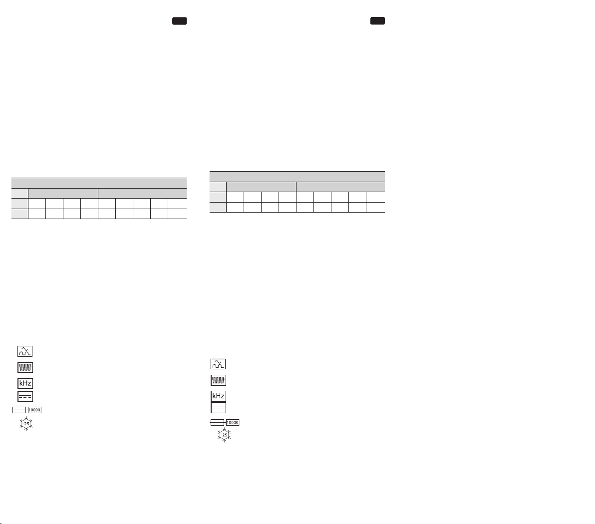
4. MAKSIMALE WERTE DER ERDUNGSWIDERSTÄNDE
REmax
UL* 50 V ~ 25 V~
I∆N 0,03 0,1 0,3 0,5 0,03 0,1 0,3 0,5 A
RE1660 500 166 100 830 250 83 50 Ω
UL *- Beruhrungsspannung
5. FUNKTIONIEREN
Die Bedingungen für das richtige Funktionieren des
Fehlerstromschutzschalters:
• der Phasenleiter und der Neutralleiter müssen durch den
Fehlerstromschutzschalter geführt werden;
• der Neutralleiter muss hinter dem Schalter ebenso wie der
Phasenleiter isoliert werden, sonst kann es zu Fehl-bzw.
Falschauslösungen kommen;
• die Erdungswiderstände dürfen die vorgeschriebenen Werte
nicht überschreiten.
6. FUNKTIONSPRÜFUNG DES SCHALTERS MIT DER
PRÜFTASTE
Wenigstens einmal in einen halben Jahr muss die Prüftaste
betätigt werden. Der Fehlerstromschutzschalter muss dabei
ausschalten.
7. ERLÄUTERUNG DER SYMBOLE AUF DEM SCHALTER UND
IN DEN ANWEISUNGEN
Fehlerstromschutzschalter für sinusförmige Wechselfeh-
lerströme und pulsierende Gleichfehlerströme
Fehlerstromschutzschalter für sinusförmige Wechselfeh-
lerströme und pulsierende Gleichfehlerströme bis 1 kHz
Fehlerstromschutzschalter für sinusförmige Wechselfeh-
lerströme und pulsierende Gleichfehlerströme bis 20 kHz
Fehlerstromschutzschalter für Gleichfehlerströme
Kurzschlussvermögen des Fehlerstromschutz-
schaltersmit Vorsicherung gL -gG
Untere Temperaturgrenze der Verwendung des
Fehlerstromschutzschalters
IN Bemessungsstrom
I∆N Bemessungsfehlerstrom
UN Bemessungsspannung
A) BILD: INTERNEN VERBINDUNGEN, B) BILD: MASSEN
C) BILD: FEHLERSTROMSCHUTZSCHALTER in 3-PHASEN SYSTEM OHNE
NEUTRALLEITER CONDUCTOR. U = 400 V; FÜR 30 mA: 2k7/1 W (500 V),
100 mA:7k5/1 W (500V), N 300 mA: 2k7/1 W (500 V);
D) BILD: FEHLERSTROMSCHUTZSCHALTER IN 1-PHASEN SYSTEM UN=230 V
D
Instructions for mounting and application
RESIDUAL CURRENT OPERATED CIRCUIT
BREAKER EFI-4B and B+
1. MOUNTING
Residual current operated circuit breaker (RCCB) can be used
in TN-S, TN-C-S, TT and IT network systems which means
in all places where neutral and protective conductor are not
connected.
RCCB shall be mounted onto a rail of 35 mm according to EN
50022.
2. CONNECTION
6 4 2 N
| | | |
5 3 1 N
The supply can be above or below.
3. MAXIMUM VALUE OF BACK-UP FUSE
For rated currents up to 63 A fuse links with the gL -gG
characteristic and rated current of 63 A should be used.
4. MAXIMUM VALUES OF EARTHING RESISTANCE
REmax
UL* 50 V ~ 25 V~
I∆N 0,03 0,1 0,3 0,5 0,03 0,1 0,3 0,5 A
RE1660 500 166 100 830 250 83 50 Ω
UL *- touch voltage
5. OPERATION
The conditions for correct operation of the RCCB:
• the phase conductor and the neutral conductor shall be
conducted through the RCCB;
• the neutral conductor shall be behind the breaker insulated
in the same way as the phase conductor, otherwise there can
appear false or unwanted tripping;
• earthing resistances shall not exceed the prescribed values.
6. TESTING OF BREAKER OPERATION WITH THE TEST
BUTTON
At least once in a half year the test button shall be actuated. On
doing this the RCCB shall switch o.
7. EXPLANATION OF THE SYMBOLS ON THE BREAKER AND
IN THE INSTRUCTIONS
RCCB for residual sinusoidal alternating and
residual pulsating direct currents
RCCB for residual sinusoidal alternating and
residual pulsating direct currents up to 1 kHz
RCCB for residual sinusoidal alternating and
residual pulsating direct currents up to 20 kHz
RCCB for direct currents
short-circuit capacity of RCCB with back-up fuse
gL -gG
lower temperature limit of use of the
RCCB
IN rated current
I∆N rated residual operating current
UN rated voltage
A) FIGURE: THE INTERNAL CONNECTIONS
B) FIGURE: DIMENSIONS
C) FIGURE: RCCB in 3-PHASE SYSTEM WITHOUT NEUTREL CONDUCTOR.
UN=400V; FOR 30mA:2k7/1W(500V), 100mA:7k5/1W (500V),
300mA: 2k7/1W(500V);
D) FIGURE: RCCB IN 1-PHASE SYSTEM UN=230 V
GB

This manual suits for next models

1

Other ETI Circuit Breaker manuals

ETI LBS-PS11 User manual

ETI

ETI LBS-PS11 User manual

ETI ETIBREAK NBS 160 User manual

ETI

ETI ETIBREAK NBS 160 User manual

ETI ETIBREAK NBS 100 User manual

ETI

ETI ETIBREAK NBS 100 User manual

ETI ETITEC B T12 User manual

ETI

ETI ETITEC B T12 User manual

ETI ETIBREAK 2 User manual

ETI

ETI ETIBREAK 2 User manual

Popular Circuit Breaker manuals by other brands

Eaton Crouse-hinds series operating instructions

Eaton

Eaton Crouse-hinds series operating instructions

Siemens SION 3AE operating instructions

Siemens

Siemens SION 3AE operating instructions

Siemens 3AH35-MA instruction manual

Siemens

Siemens 3AH35-MA instruction manual

GE POWER BREAK MICRO-VERSATRIP E39ME20 instructions

GE

GE POWER BREAK MICRO-VERSATRIP E39ME20 instructions

Eaton PKZM0 PI Series Instruction leaflet

Eaton

Eaton PKZM0 PI Series Instruction leaflet

Allen-Bradley 140G Series Installation

Allen-Bradley

Allen-Bradley 140G Series Installation

Cutler-Hammer VCP-W instructions

Cutler-Hammer

Cutler-Hammer VCP-W instructions

Siemens 3VA9908 - 0BB Series operating instructions

Siemens

Siemens 3VA9908 - 0BB Series operating instructions

AEG ME10 manual

AEG

AEG ME10 manual

Kaco blueplanet hy-switch operating instructions

Kaco

Kaco blueplanet hy-switch operating instructions

NHP TemBreak PRO user manual

NHP

NHP TemBreak PRO user manual

bonitron M3675T Customer Reference Manual

bonitron

bonitron M3675T Customer Reference Manual

Eaton PKE12 Series manual

Eaton

Eaton PKE12 Series manual

PCE Health and Fitness PRCD-S+ operating manual

PCE Health and Fitness

PCE Health and Fitness PRCD-S+ operating manual

ABB GE SPST480 instructions

ABB

ABB GE SPST480 instructions

LEGRAND DMX-SP 4000 manual

LEGRAND

LEGRAND DMX-SP 4000 manual

ABB DS 261 Installation and operating instructions

ABB

ABB DS 261 Installation and operating instructions

Siemens 3VT9500-8LC10 operating instructions

Siemens

Siemens 3VT9500-8LC10 operating instructions

manuals.online logo
manuals.online logoBrands
  • About & Mission
  • Contact us
  • Privacy Policy
  • Terms and Conditions

Copyright 2025 Manuals.Online. All Rights Reserved.