Siemens RS-485 User manual

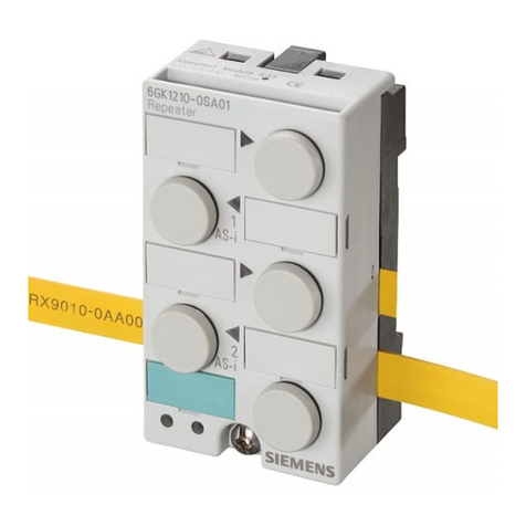
RS 485 Repeater
_
_________________
_
_
_________________
_
_
_________________
_
_
_________________
_
_
_________________
_
_
_________________
_
_
_________________
_
SIMATIC
RS 485 Repeater
Manual
02/2011
A5E03382072-01
Preface
1
Introduction
2
Description
3
Installation
4
Connecting
5
Technical data
6
Dimension drawings
7

Legal information
Legal information
Warning notice system
This manual contains notices you have to observe in order to ensure your personal safety, as well as to prevent
damage to property. The notices referring to your personal safety are highlighted in the manual by a safety alert
symbol, notices referring only to property damage have no safety alert symbol. These notices shown below are
graded according to the degree of danger.
DANGER
indicates that death or severe personal injury will result if proper precautions are not taken.
WARNING
indicates that death or severe personal injury may result if proper precautions are not taken.
CAUTION
with a safety alert symbol, indicates that minor personal injury can result if proper precautions are not taken.
CAUTION
without a safety alert symbol, indicates that property damage can result if proper precautions are not taken.
NOTICE
indicates that an unintended result or situation can occur if the corresponding information is not taken into
account.
If more than one degree of danger is present, the warning notice representing the highest degree of danger will
be used. A notice warning of injury to persons with a safety alert symbol may also include a warning relating to
property damage.
Qualified Personnel
The product/system described in this documentation may be operated only by personnel qualified for the specific
task in accordance with the relevant documentation for the specific task, in particular its warning notices and
safety instructions. Qualified personnel are those who, based on their training and experience, are capable of
identifying risks and avoiding potential hazards when working with these products/systems.
Proper use of Siemens products
Note the following:
WARNING
Siemens products may only be used for the applications described in the catalog and in the relevant technical
documentation. If products and components from other manufacturers are used, these must be recommended
or approved by Siemens. Proper transport, storage, installation, assembly, commissioning, operation and
maintenance are required to ensure that the products operate safely and without any problems. The permissible
ambient conditions must be adhered to. The information in the relevant documentation must be observed.
Trademarks
All names identified by ® are registered trademarks of the Siemens AG. The remaining trademarks in this
publication may be trademarks whose use by third parties for their own purposes could violate the rights of the
owner.
Disclaimer of Liability
We have reviewed the contents of this publication to ensure consistency with the hardware and software
described. Since variance cannot be precluded entirely, we cannot guarantee full consistency. However, the
information in this publication is reviewed regularly and any necessary corrections are included in subsequent
editions.
Siemens AG
Industry Sector
Postfach 48 48
90026 NÜRNBERG
GERMANY
A5E03382072-01
Ⓟ 03/2011
Copyright © Siemens AG 2011.
Technical data subject to change
RS 485 Repeater
Manual, 02/2011, A5E03382072-01 3
Table of contents
1 Preface ...................................................................................................................................................... 5
2 Introduction................................................................................................................................................ 7
3 Description................................................................................................................................................. 9
3.1 Area of application and properties .................................................................................................9
3.2 Design of the RS 485 repeater ....................................................................................................11
4 Installation ............................................................................................................................................... 13
4.1 Installing and uninstalling the RS 485 repeater ...........................................................................13
5 Connecting .............................................................................................................................................. 17
5.1 RS 485 Repeater in ungrounded and grounded operation..........................................................17
5.2 Connecting the power supply.......................................................................................................20
5.3 Connecting the bus cable ............................................................................................................21
5.4 Configuration options with the RS 485 repeater..........................................................................22
6 Technical data ......................................................................................................................................... 25
6.1 General technical data .................................................................................................................25
6.1.1 Standards and approvals.............................................................................................................25
6.1.2 Electromagnetic Compatibility......................................................................................................30
6.1.3 Shipping and storage conditions for modules and backup batteries ...........................................32
6.1.4 Mechanical and ambient climatic conditions for S7-300 operation..............................................33
6.1.5 Specification of dielectric tests, protection class, degree of protection, and rated voltage
of S7-300......................................................................................................................................35
6.2 Technical data the RS 485 Repeater...........................................................................................36
7 Dimension drawings ................................................................................................................................ 39
7.1 Dimension drawings.....................................................................................................................39
Glossary .................................................................................................................................................. 41
Index........................................................................................................................................................ 45

Table of contents
RS 485 Repeater
4 Manual, 02/2011, A5E03382072-01

RS 485 Repeater
Manual, 02/2011, A5E03382072-01 5
Preface 1
Introduction
This manual describes the RS 485 repeater.
It supports you during the configuration, installation and commissioning. It is intended for
people who work in the following areas: the configuring, commissioning and servicing of
automation systems.
Basic knowledge required
This manual presumes general knowledge in the field of automation engineering.
Range of validity of this manual
The manual is valid for the RS 485 repeater with the order number 6ES7972-0AA02-0XA0.
Additional support
If you have any questions relating to the products described in this product information and
do not find the answers in this document, please contact your local Siemens representative
on the Internet (http://www.automation.siemens.com/partner/).
A guide to the technical documentation provided for the various SIMATIC products and
systems is available on the Internet (http://www.siemens.com/simatic-tech-doku-portal).
The online catalog and ordering systems are available on the Internet
(http://www.siemens.com/automation/mall).
Technical Support
You can contact Technical Support for all Industry Automation products by means of the
Internet Web form for the Support Request on the Internet
(http://www.siemens.com/automation/support-request).
Additional information about Siemens Technical Support is available on the Internet
(http://www.siemens.com/automation/service).

Preface
RS 485 Repeater
6 Manual, 02/2011, A5E03382072-01
Service & Support on the Internet
In addition to our documentation, we offer a comprehensive knowledge base. On the Internet
(http://www.siemens.com/automation/service&support).
There you will find:
● Our Newsletter, which constantly provides you with the latest information about your
products.
● The right documentation for you using our Service & Support search engine.
● The bulletin board, a worldwide knowledge exchange for users and experts.
● Your local contact for Automation & Drives in our contact database.
● Information about on-site services, repairs, spare parts, and lots more.

RS 485 Repeater
Manual, 02/2011, A5E03382072-01 7
Introduction 2
This chapter
This chapter describes the RS 485 repeater in detail.
This includes:
● Description of the RS 485 repeater
● The maximum cable lengths between two RS 485 repeaters
● The functions of the various operating elements and terminals
● Mounting and removing
● information about grounded and nongrounded operation
● Connecting the power supply and bus line
● Technical specifications and the block diagram
● Dimension drawings
Diagnostic Repeater
Compared to the RS 485 repeater, the Diagnostic Repeater has new characteristics:
Diagnostic function and modeling as the DP slave. For additional information, refer to the
Diagnostic Repeater for PROFIBUS DP manual on the Internet
(http://support.automation.siemens.com/WW/view/en/7915183).

Introduction
RS 485 Repeater
8 Manual, 02/2011, A5E03382072-01

RS 485 Repeater
Manual, 02/2011, A5E03382072-01 9
Description 3
3.1 Area of application and properties
Order number
6ES7972-0AA02-0XA0
What is the RS 485 repeater?
The RS 485 repeater amplifies data signals (amplitude, edge slope and signal width) on bus
lines and couples segments.
Application of the RS 485 Repeater
The RS 485 repeater connects two PROFIBUS or MPI segments using RS 485 technology
with maximum 32 nodes. It enables transfer rates from 9.6 kbps to 12 Mbps.
You need an RS 485 repeater if:
● More than 32 nodes (maximum 127, including repeaters) are connected to the bus
● Segments are operated ungrounded on the bus (electrical isolation of segments)
● The maximum cable length of a bus segment is exceeded (see the table below)
● Help is required during the commissioning
– Switch for disconnecting segments
– Display of bus activity
– Disconnecting a bus segment in the case of incorrectly inserted terminating resistors
● The signals are to be regenerated in amplitude and time
Table 3- 1 Maximum cable length of a bus segment
Transmission rate Max. cable length of a bus segment (in m)
9.6 to 187.5 kbps 1000
500 kbps 400
1.5 Mbps 200
3 to 12 Mbps 100

Description
3.1 Area of application and properties
RS 485 Repeater
10 Manual, 02/2011, A5E03382072-01
Rules
If you set up a PROFIBUS network with RS 485 repeaters:
● The number of RS 485 repeaters in series must be configured in STEP 7.
● Up to nine RS 485 repeaters may be connected in series.
● The maximum cable length between two nodes with RS 485 repeater may not exceed the
values listed in the table below.
Table 3- 2 Maximum cable length between two RS 485 repeaters
Transmission rate Maximum cable length between 2 nodes (in m) with RS 485 repeater
9.6 to 187.5 kbps 10000
500 kbps 4000
1.5 Mbps 2000
3 to 12 Mbps 1000

Description
3.2 Design of the RS 485 repeater
RS 485 Repeater
Manual, 02/2011, A5E03382072-01 11
3.2 Design of the RS 485 repeater
The following table shows the design and functions of the RS 485 repeater.
Table 3- 3 Design and functions of the RS 485 repeater
Design of the repeater no. Function
① Connection for the RS 485 repeater power supply (pin "M5.2" is the
ground reference, if you want to measure the voltage difference
between terminals "A2" and "B2").
② Shield clamp for the strain relief and grounding of the bus cable of bus
segments 1 or 2
③ Terminals for the bus cable of bus segment 1
④ Switches for terminating resistance for bus segment 1
⑤ LED for bus segment 1
⑥ OFF switch
(= isolate bus segments from each other, for example, for
commissioning)
⑦ LED for bus segment 2
⑧ Switches for terminating resistance for bus segment 2
⑨ LED 24 V supply voltage
⑩ Terminals for the bus cable of bus segment 2
⑪ Slide for mounting and removing the RS 485 repeater on the standard
mounting rail
/
$
21
21
2))
'3
6
6
'3
02'(
'&9
3*
23
56
5(3($7(5
(6
$$;$
;
% $ %
$ % $ %
03(0
s
⑫ Interface for PG/OP on bus segment 1
Note
Terminal M 5.2 of the power supply serves as ground reference for signal measurements in
the event of a fault and should not be wired.

Description
3.2 Design of the RS 485 repeater
RS 485 Repeater
12 Manual, 02/2011, A5E03382072-01

RS 485 Repeater
Manual, 02/2011, A5E03382072-01 13
Installation 4
4.1 Installing and uninstalling the RS 485 repeater
Overview
You can install the RS 485 repeater as follows:
● On an S7-300 mounting rail
● On a standard mounting rail (order number 6ES5710-8MA..)
Installation on an S7-300 mounting rail
To install the RS 485 repeater on an S7-300 mounting rail, the catch on the rear of the
RS 485 repeater must first be removed (see the following figure):
1. Insert a screwdriver below the tongue of the catch (1) and
2. Push the screwdriver towards the rear of the module (2). Hold the screwdriver in this
position!
Result: The catch of the RS 485 repeater is released.
3. Using your free hand lift the catch up as far as it will go and then remove the catch (3).
Result: The catch is removed from the RS 485 repeater.
4. Fit the RS 485 repeater into the S7300 mounting rail (4).

Installation
4.1 Installing and uninstalling the RS 485 repeater
RS 485 Repeater
14 Manual, 02/2011, A5E03382072-01
5. Push it towards the back as far as it will go (5).
6. Tighten the securing screw with a torque of 80 to 110 Ncm (6).
4
5
6
3
1
2
Rear: Front:
80 to 110 Ncm
Figure 4-1 Installing the RS 485 repeater on an S7-300 mounting rail
Removing the repeater from an S7-300 mounting rail
To remove the RS 485 repeater from the S7-300 mounting rail:
1. Loosen the fixing screw of the RS 485 repeater (1) and
2. Pull the RS 485 repeater up and out (2).
2
1
Figure 4-2 Removing the RS 485 repeater from the S7-300 mounting rail

Installation
4.1 Installing and uninstalling the RS 485 repeater
RS 485 Repeater
Manual, 02/2011, A5E03382072-01 15
Installation on a standard mounting rail
To be able to install the repeater on a standard mounting rail, the catch must be present on
the rear of the RS 485 repeater:
1. Fit the RS 485 repeater into the standard mounting rail from above and
2. Push it towards the back until the catch locks it in place.
Removal from the standard mounting rail
To remove the RS 485 repeater from the standard mounting rail:
1. Press down the catch on the bottom of the RS 485 repeater using a screwdriver and
2. Pull the RS 485 repeater upwards and out to remove it from the standard mounting rail.

Installation
4.1 Installing and uninstalling the RS 485 repeater
RS 485 Repeater
16 Manual, 02/2011, A5E03382072-01

RS 485 Repeater
Manual, 02/2011, A5E03382072-01 17
Connecting 5
5.1 RS 485 Repeater in ungrounded and grounded operation
Grounded or ungrounded
The RS 485 repeater is
● Grounded, if all other nodes on the bus segment are also operated on ground potential
● Ungrounded, if all other nodes in the bus segment are operated on ungrounded potential
Note
Bus segment 1 is referenced to ground if you connect a PG to the PG/OP socket of the
RS 485 repeater. The bus segment is grounded because the MPI in the PG is grounded,
and the PG/OP socket of the RS 485 repeater is connected internally with bus segment
1.
Grounded operation of the RS 485 Repeater
For grounded operation of the RS 485 repeater, you must bridge terminals "M" and "PE" on
the top of the RS 485 repeater.
Ungrounded operation of the RS 485 repeater
For ungrounded operation of the RS 485 repeater, do not interconnect "M" and "PE" on the
top of the RS 485 repeater. In addition, the supply voltage to the RS 485 repeater must be
ungrounded.

Connecting
5.1 RS 485 Repeater in ungrounded and grounded operation
RS 485 Repeater
18 Manual, 02/2011, A5E03382072-01
Wiring diagram
In a repeater configuration with ungrounded reference potential (ungrounded operation), any
interference currents and static charges are discharged to the protective conductor by
means of an RC network integrated in the repeater (refer to the figure below).
3(
0
Q) 0വ
/
$ % $ %
03(0
s
① Ground busbar

Connecting
5.1 RS 485 Repeater in ungrounded and grounded operation
RS 485 Repeater
Manual, 02/2011, A5E03382072-01 19
Electrical isolation between bus segments
Bus segments 1 and 2 are electrically isolated. The PG/OP interface is connected internally
to the port for bus segment 1. The figure below shows the front panel of the RS 485
repeater.
$
56
5(3($7(5
(6
$$;$
% $ %
$ % $ %
/
;
03(0
21
21
2))
'3
6
6
'3
02'(
'&9
3*
23
s
① PG/OP interface
② Terminals for bus segment 1
③ Terminals for bus segment 2
④ Electrical isolation

Connecting
5.2 Connecting the power supply
RS 485 Repeater
20 Manual, 02/2011, A5E03382072-01
Amplification of bus signals
The amplification of the bus signals takes place between the port for bus segment 1 or the
PG/OP interface and the port for bus segment 2.
5.2 Connecting the power supply
Cable type
To connect the 24 V DC power supply, use flexible cables with a cross section of 0.25 mm2
to 2.5 mm2 (AWG 26 to 14).
Connecting the power supply
To connect the power supply of the RS-485 repeater:
● Strip the insulation from the cable for the 24 V DC power supply.
● Connect the cable to terminals "L+", "M" and "PE".
Other manuals for RS-485
2
Table of contents
Other Siemens Repeater manuals

Siemens
Siemens SIMATIC NET AS-Interface User manual

Siemens
Siemens Gigaset Repeater User manual

Siemens
Siemens 7XV5452-0AA00 User manual

Siemens
Siemens Gigaset Repeater User manual

Siemens
Siemens Gigaset SE365 WLAN User manual

Siemens
Siemens Gigaset Optical LAN Adapter Duo User manual

Siemens
Siemens 7XV5451-0 A00 Series User manual

Siemens
Siemens Gigaset 108 User manual

Siemens
Siemens 7XV5461-0B 00 Series Manual

Siemens
Siemens FT2010 User manual