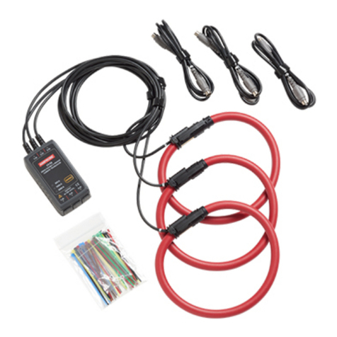
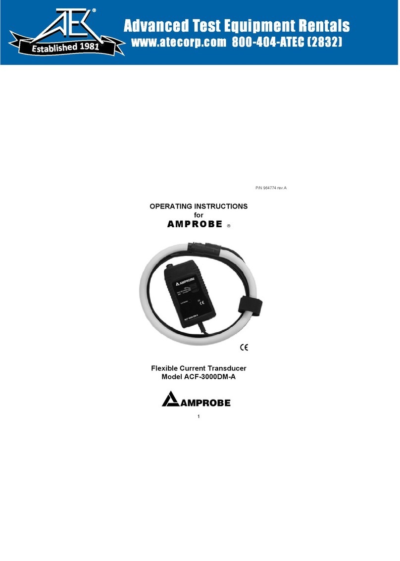
Amprobe CT-500 User manual

CT-500
1000 A Flexible Neutral Current Transducer
Instruction Manual
Manual de usuario
Manuel de l’utilisateur


CT-500
1000 A Flexible Neutral Current
Transducer
Instruction Manual
11/2015, 6006997 A
©2015 Amprobe.
All rights reserved. Printed in Japan
English

Limited Warranty and Limitation of Liability
Your Amprobe product will be free from defects in material and workmanship for one
year from the date of purchase unless local laws require otherwise. This warranty does
not cover fuses, disposable batteries or damage from accident, neglect, misuse, alteration,
contamination, or abnormal conditions of operation or handling. Resellers are not
authorized to extend any other warranty on the behalf of Amprobe. To obtain service
during the warranty period, return the product with proof of purchase to an authorized
Amprobe Service Center or to an Amprobe dealer or distributor. See Repair Section for
details. THIS WARRANTY IS YOUR ONLY REMEDY. ALL OTHER WARRANTIES - WHETHER
EXPRESS, IMPLIED OR STATUTORY - INCLUDING IMPLIED WARRANTIES OF FITNESS FOR A
PARTICULAR PURPOSE OR MERCHANTABILITY, ARE HEREBY DISCLAIMED. MANUFACTURER
SHALL NOT BE LIABLE FOR ANY SPECIAL, INDIRECT, INCIDENTAL OR CONSEQUENTIAL
DAMAGES OR LOSSES, ARISING FROM ANY CAUSE OR THEORY. Since some states or
countries do not allow the exclusion or limitation of an implied warranty or of incidental or
consequential damages, this limitation of liability may not apply to you.
Repair
All Amprobe returned for warranty or non-warranty repair or for calibration should be
accompanied by the following: your name, company’s name, address, telephone number,
and proof of purchase. Additionally, please include a brief description of the problem or
the service requested and include the test leads with the meter. Non-warranty repair or
replacement charges should be remitted in the form of a check, a money order, credit
card with expiration date, or a purchase order made payable to Amprobe.
In-warranty Repairs and Replacement – All Countries
Please read the warranty statement and check your battery before requesting repair.
During the warranty period, any defective test tool can be returned to your Amprobe
distributor for an exchange for the same or like product. Please check the “Where to
Buy” section on www.Amprobe.com for a list of distributors near you. Additionally, in the
United States and Canada, in-warranty repair and replacement units can also be sent to an
Amprobe Service Center (see address below).
Non-warranty Repairs and Replacement – United States and Canada
Non-warranty repairs in the United States and Canada should be sent to an Amprobe Service
Center. Call Amprobe or inquire at your point of purchase for current repair and replacement
rates.
USA: Canada:
Amprobe Amprobe
Everett, WA 98203 Mississauga, ON L4Z 1X9
Tel: 888-993-5853 Tel: 905-890-7600
Fax: 425-446-6390 Fax: 905-890-6866

1
CT-500 1000 A Flexible Neutral Current Transducer
CONTENTS
INTRODUCING THE CT-500 ............................................................................... 2
SYMBOL............................................................................................................. 3
SAFETY INFORMATION..................................................................................... 3
MEASUREMENTS............................................................................................... 5
MAINTENANCE.................................................................................................. 7
SPECIFICATIONS ................................................................................................ 8

2
INTRODUCING THE CT-500
The CT-500 Flexible Neutral Current Transducer is an optional accessory that
is used to measure current on the Amprobe DM-5 Power Quality Analyzer.
The flexible and lightweight measuring head allows for quick and easy
installation in hard to reach areas.
Cable
Power
indicator
Output
cable
Flexible measuring head
Output terminal plug
Coupling point of the measuring head
Pins of output terminal
Not usedOutput (Hi)
COM (Output Lo) Not used
-3.0 to -5.5 V3.0 to 5.5 V
Output signal is between pin 3 and 5.
The measuring head is powered via pin 1 and 3 (3.0 to 5.5 Vdc) and pin 2 and
3 (-3.0 to -5.5 Vdc).
Connecting terminal on DM-5 is symmetrical to above pin configurations.

3
SYMBOLS
Do not apply around, or remove from, HAZARDOUS LIVE
conductors.
Caution! Risk of electric shock.
WCaution! Refer to the explanation in this manual.
BAlternating current (AC).
TThe equipment is protected by double insulation or reinforced
insulation.
Underwriters Laboratories (applies to Canada and U.S.A.)
PComplies with European directives.
Conforms to relevant Australian standards
=Do not dispose this product as unsorted municipal waste.
Contact aqualified recycler.
SAFETY INFORMATION
The current transducer complies with:
• UL/IEC 61010-1, Measurement CAT III 600 V, CAT IV 300 V, Pollution
degree 2
• IEC 61010-2-030
• IEC 61010-2-032
• EMC IEC 61326-1
CENELEC DIRECTIVES
The instruments conform to CENELEC Low-voltage directive 2006/95/EC and
Electromagnetic compatibility directive
2004/108/EC.

4
W
Warning: Read before Using
To ensure safe operation and service of the current transducer, follow these
instructions:
• Read the operating instructions before use and follow all safety
instructions.
• Use the current transducer only as specified in the operating
instructions; otherwise the current transducer’s safety features may be
compromised.
• Adhere to local and national safety codes. Individual protective
equipment must be used to prevent shock and arc blast injury where
hazardous live conductors are exposed.
• Before each use, inspect the current transducer and its latching system
for any damage. Pay particular attention to the insulation surrounding
the flexible measuring head. Look for cracks or missing portions of the
transducer housing or output cable insulation. Also look for loose or
weakened components.
• Do not use a current transducer that is cracked, damaged, or has a
defective cable.
• Never use the current transducer on a circuit with voltages higher than
600 V CAT III and 300 V CAT IV.
−CATIIIequipmentisdesignedtoprotectagainsttransientsin
equipment in fixed equipment installations, such as distribution
panels, feeders and short branch circuits, and lighting systems in
large buildings.
• De-energize the installation on which current will be measured or adopt
safe operating procedures during application and removal of the current
transducer.
• Use extreme caution when working around bare conductors or bus bars.
• Do not use the current transducer to measure bare conductors carrying a
voltage from 30V up to 600V unless you are wearing protective clothing
suitable for high-voltage work. Contact with the conductor could
result in electric shock. Always use appropriate equipment for personal
protection.
• Use caution when working with voltages above 60 V dc, 30 V ac rms or
42 V ac peak. Such voltages pose a shock hazard.
• Never apply the current exceeding the measuring range.
• Ensure that no foreign object obstructs the latching mechanism.
• Do not operate the current transducer around explosive gas, vapor, or
dust.
• Do not step on or pinch the cord. It may damage the insulation.
• Do not expose the current transducer to direct sunlight, high
temperatures/humidity or dew. It may cause deformation or insulation
degradation.

5
MEASUREMENTS
W
Warning
To avoid electric shock or personal injury:
• Do not use the transducer on a circuit with voltages higher than 600 V
CAT III and 300 V CAT IV.
• De-energize the installation on which current will be measured or adopt
safe operating procedures during application and removal of the current
transducer.
• Disconnect CT-500 from DM-5 by removing the CT-500 output terminal
plug. Do not pull CT-500 output cable.
To measure AC current:
1. Connect CT-500 output terminal to DM-5 current input terminal (A1).
Observe the arrow marks for correct connection.

6
2. Power on DM-5 (unit auto-detects the current transducer connected).
3. Unlock the flexible measuring head according to the followings:
Coupling point
Cable Lock
Flexible measuring head
1Push to unlock
2Remove from
coupling point
4. Connect the flexible measuring head around the conductor.
5. Make sure the arrow marked on the measuring head coupling points
towards the current flowing direction of the conductor, and position the
conductor under test as shown below.

7
Reference measurement
position of the conductor
a
Note 2
Note 1
Note 1: Reference measurement position of the conductor. Maximum
coupling diameter: 20 mm for published accuracy.
Note 2: Keep minimum 90 mm to ensure published accuracy.
6. Ensure the coupling point of the flexible measuring head is firmly locked.
W
Caution
• The coupling point may disconnect if excessive pulling force is applied.
• Clamp onto one conductor only. Measurement cannot be made when
clamping single-phase (2-wire) or threephase (3-wire) at the same time.

8
MAINTENANCE
Before each use, inspect the flexible current transducer and its latching
system for any damage for continued safety. Pay particular attention to the
insulation surrounding the flexible measuring head.
The flexible current transducer and its latching system require no special
care. Ensure that no foreign object obstructs the latching mechanism. Clean
the CT-500 with a damp cloth and a mild detergent. Do not use abrasives,
solvents, or alcohol.
If CT-500 does not perform properly, use the following steps to help isolate
the problem:
• Inspect the coupling system for any damage. If a foreign material is
present, the coupling system will not close properly and errors will
result.
• Inspect the cables between the flexible measuring head and CT-500
circuit box. Also inspect between CT-500 circuit box and DM-5 for any
damage.
• Check the power ON LED on the circuit box is ON.
• Verify the transducer setting on DM-5 is correct.
SPECIFICATIONS
Current range 1000 A
AC rms
Output voltage 500 mVac / 1000 Aac (0.5 mV / A)
Measuring range 0 to 1000 A (1850 Apeak)
Conductor size Ø20 mm (0.787 in) maximum for published accuracy
Accuracy (sine wave)* ±0.8% ± 0.2 mV (45 Hz to 65 Hz)
±1.5% ± 0.2 mV (40 Hz to 1 kHz)
Phase characteristics 45 Hz to 65 Hz within ±2o
40 Hz to 1 kHz within ±3o
Working voltage 600 Vac rms
Max allowed input 1300 Aac continuous
Possible measurable
conductor size
Max. Ø110 mm diameter (accuracy error not
specified)
Head circumference 400 mm (15.75 in)

9
Head cable diameter 8.5 mm (0.33 in)
Cable length (head
to electronics) Approx. 2.7 m (8.56 ft)
Cable length
(output cable) Approx. 0.2 m (0.66 ft)
Output terminal Mini-DIN-6 connector
Output impedance 100 Ωor less
Current consumption
(at power supply 5 V) Max. 2 mA (typical)
Operating
temperature and
humidity
14oF to 122 oF (-10 oC to 50 oC), ≤85 %RH (no
condensation)
Guaranteed accuracy at 73 oF ± 9 oF (23 oC ± 5 oC),
≤85 %RH (no condensation)
Storage temperature
and humidity
-4 to 140 oF (-20 oC to 60 oC), ≤85 % RH (no
condensation)
Operating altitude 0 to 2000 m
EMC EN 61326-1
Safety compliance
UL/IEC 61010-1, IEC 61010-2-030,
IEC 61010-2-032 Measurement CAT III 600 V,
CAT IV 300 V, Pollution degree 2
Certification P
Weight Approx. 180 g (0.4 lb)
* See Note 1 and Note 2 on page 7 for reference measurement position of
the conductor

Please
Recycle
Amprobe®
www.Amprobe.com
Everett, WA 98203
Tel: 877-AMPROBE (267-7623)
Visit www.Amprobe.com for
• Catalog
• Application notes
• Productspecications
• User manuals
Table of contents
Other Amprobe Transducer manuals