Amptec Research 640N Manual

PHONE (512) 858-4045; FAX +01 (512) 858-4540; TOLL FREE IN USA 800-430-5440
website http://www.amptec.com
640N WATER-RESISTANT
IGNITER TESTER
OPERATION /MAINTENANCE MANUAL
2000 W20 W200 KW2.0 MW
1.5 µA .15 µA
150 µA
8 mA
<
1.0 M OHM
1.9 M OHM
640N

TABLE OF CONTENTS
_______________________________________________________________
CHAPTER A: RECEIVING AND INITIAL INSPECTION
A-1 Introduction to the AMPTEC 640N
A-2 Receiving, Unpacking and Initial Inspection
A-3 Opening the 640N Ohmmeter and Removal of the Lid
A-4 AC Adaptor/ Battery Charger- Power Requirements
A-5 Setup and Use
CHAPTER B: 640N FAILSAFE OHMMETER SPECIFICATIONS
Table B-2. Specifications
CHAPTER C: REPLACEMENT, OPTIONAL AND ACCESSORY ITEMS
C-1 Available Accessories and Options
C-2 Test Lead Sets
CHAPTER D: OPERATION, FUNCTIONAL SELF-TEST AND USE
D-1 General
D-2 Front Panel Features and Operation
D-3 Complete 640N Front Panel Diagram
D-4 Fuse Holder
D-5 4-Wire Resistance Measurement
Figure D-1. Error Sources in Resistance Measurements
D-6 Connections
D-7 Failsafe Operation
D-8 Battery Monitoring Circuitry

CHAPTER E: GENERAL OPERATION AND DESIGN
E-1 General
E-2 Troubleshooting
E-3 Circuit Descriptions
E-4 Analog-to-Digital Converter
E-5 Ohms-to-DC Converter
E-6 Failsafe Design
E-7 Ultra-Safe Power Supply Scheme
Figure E-1. Model 640N Block Diagram
Figure E-1B Analog-to-Digital Converter Timing Diagram
Figure E-2 Analog Section of IC1 and IC2
Figure E-3. Constant Current Source Diagram (Simplified)
Figure E-4. LED Display Pin Functions
E-8. Relay Board
CHAPTER F: ROUTINE MAINTENANCE
F-1 General
F-2 Required Test Equipment
F-3 Calibration Procedure
F-4 Battery Replacement Instructions

A-1. Introduction to the AMPTEC 640N
The AMPTEC 620A, 630 and now the 640
Series Igniter Testers/Failsafe Ohmmeters are
becoming the standard in the Safety Igniter
Circuit Test industry, and are designed to
provide extremely safe and reliable resistance
testing of explosive or volatile devices. Safety
Approvals from various Safety Boards include,
the U.S. Air Force ( 620A-4) for generic use on
Non-Nuclear munitions and the US NAVAL
ORDNANCE CENTER (630AN and other
versions pending). Some of the devices the
640N Failsafe Ohmmeter may be used on
include: fuses, squibs, igniters, explosive bolts,
rocket motor squibs, automobile air-bag
initiators and many others.
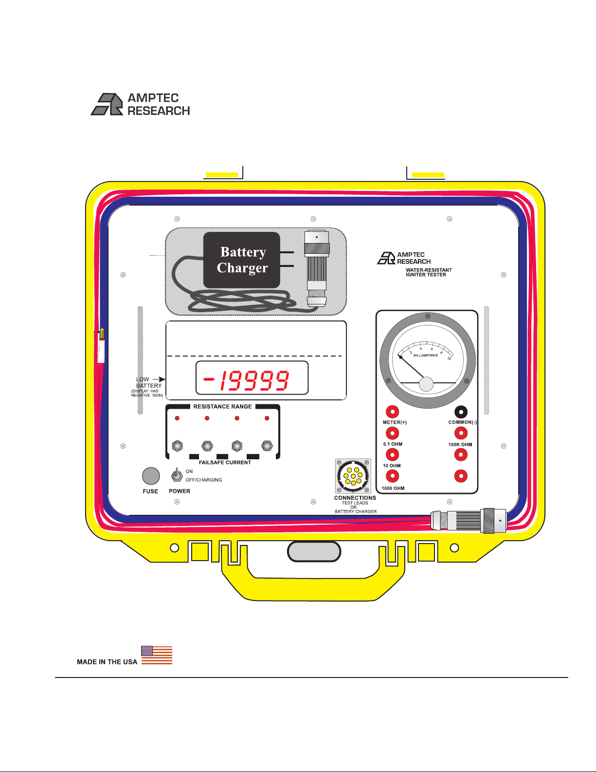
The AMPTEC 640N is a 4-wire failsafe digital
ohmmeter which has been designed to reliably
use very low test currents for its resistance
measurement. Failsafe Output Circuitry
proprietary to AMPTEC RESEARCH insures
that test current levels do not exceed the
specified "failsafe current" even in a worst-case
component failure situation. The failsafe feature
is tested in every instrument before shipment.
An On board DC Milliammeter also lets the user
verify actual 640N current output levels, prior to
connection to a squib or detonator.
The 620A and the newer 640 series represent the
latest in ultra-safe Igniter Tester measurements.
The 640N uses the same main printed circuit
board (PCB) as the AMPTEC 620A Igniter
Tester. The 640N has been made water-resistant
and has many features which make it useful in a
variety of applications. Please check the last
chapter of this manual for addendums that may
apply to new 640Ns and 630AN conversions.
Should the rechargeable batteries reach a low
charge level a negative sign will apear on the
display. The 640N has a battery monitoring
circuit that indicates it is time to plug in the
battery charger.
A-2. Receiving, Unpacking, and Initial
Inspection
Should the AMPTEC shipping box appear
damaged upon arrival, request that the carrier's
agent (i.e. UPS) be present when the unit is
unpacked. If the 640N appears damaged, the
carrier's agent should authorize repairs before
the unit is returned to the factory. Even if the
instrument appears undamaged, it may have
suffered internal damage in transit that may not
be evident until the unit is operated or tested to
verify conformance with its specifications. You
may refer to the Functional Test section of
Section D of this manual to help identify the
problem (i.e Test leads etc.)
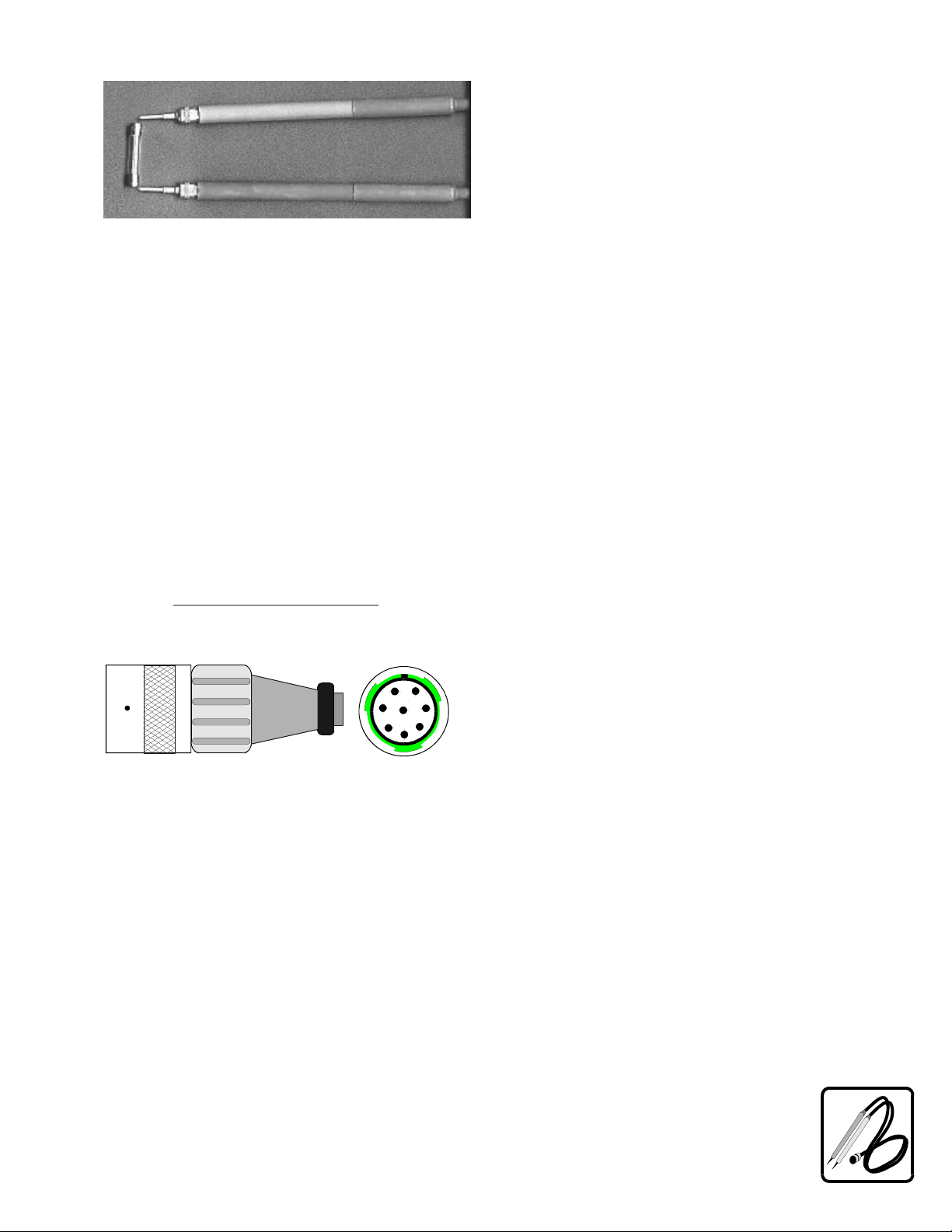
The 640N has a set of test
resistors built-in the
Functional Test Section that
can quickly help the user
figure out where the
problem is most of the time.
If the unit fails to operate or
fails to meet the performance specifications of
Section B, notify the carrier's agent and the
nearest AMPTEC Sales Office. Retain the
shipping carton for the carrier's inspection. DO
NOT return equipment to AMPTEC
RESEARCH or any of its sales offices without
first obtaining an (RMA) Return Material
Authorization number. We need to know who to
contact and how to contact (i.e. phone number
and FAX number) in order to properly
coordinate the return of the repaired AMPTEC
product.
By calling AMPTEC RESEARCH first, prior
to just returning the 640N, we can often
troubleshoot (based on the symptoms you
describe) and identify the problem over the
phone (i.e battery loose in the battery holder).
We may possibly be able to fix the problem over
the phone and prevent you from having to return
the unit to AMPTEC for repair.
R M A
SECTION A - RECEIVING AND INITIAL INSPECTION

A-3. Opening the 640N Igniter Tester and
removal of the Lid
When closed, the 640N Ohmmeter has two
large O-rings that provide a very water resistant
and on occasion even an air tight seal. By
pressing down with your palm as diagramed
above you compress the O-ring in the lid of the
640A. This makes it easier to flip up the release
latch. Repeat the palm press step on the other
corner of the 640N while flipping up the release
latch. At this point the 640N lid will normally be
able to be raised, and placed in an open lid state.
If the 640N doesn’t open after flipping up the
release latches, a change in atmospheric
pressure since the unit was last closed may be
the culprit. Turn the Air Pressure Equalization
or “Purge Valve” counter-clockwise. Once air-
pressure is equalized, the 640N can be opened.
If the Purge Valve was opened, return the valve
to the closed state (tighten = clockwise) once the
640N lid is open.
The 640N has a way to remove it’s lid
completely, for example when used in an indoor
laboratory environment. With the 640N open,
remove the units two hinge pins (hex type) by
twisting them. The lid should come free at the
hinge. Once the lid is removed replace the hinge
pins in the hole they were pulled out of.
A-4. AC/DC Battery Charger - Power
Requirements
The AMPTEC 640N is powered by an internal
rechargeable heavy-duty nickel-cadmium
battery pack (4 ea D cell - 5.7 AHr).
Replacement batteries may be purchased,
contact the sale department at AMPTEC
RESEARCH.
The battery charger is an external AC/DC
converter that plugs into a standard 115VAC
receptacle. The AC adapter provides 9VDC @
1.1amperes. The AC Adapter Battery Charger is
configured with a notched connector that plugs
into the “mating” notched “J1” connector on the
640N front panel.
RESEARCH
AMPTEC
640N
Press Down with Palm here
While opening release Latch A
Press Down with Palm here
While opening release Latch B
Remove both hinge pins (hex type)
with lid open to remove lid from its hinge
A. Release Latch B. Release Latch
C. Air Pressure Equalization (Purge Valve)

For safety reasons, the battery charger’s
notched connector blocks access to the test lead
connections that are also part of the 640N keyed
connector. The main “J1” 640N connector is a
single access or one use at a time Safety
Protection Device. In this way the 640N user
can not ever connect any test leads while the
unit is charging. The 640N test leads have to
use the same J1 notched connector. The 640N is
designed so it is impossible to be powered (in
operating - measurement mode) directly from
the AC line adapter. As an additional note, the
640N main power switch must also be in the
“Off/Charging” mode in order for the
connected battery charger to recharge the
640A’s batteries.
For customers using 220VAC 50 HZ AC line
power for running the battery charger, please
inform AMPTEC’s sales department at the time
of your order and the appropriate adaptor will
be included with the 640N Failsafe Ohmmeter
shipment for an additional fee.
A fully charged battery pack typically powers
the 640N for approximately 8 hours before
requiring a recharge. AMPTEC installs a quality
set of 4 each Heavy Duty (5700 mAHr) Ni-Cad
batteries. The 640N will also operate on a 4000
mAhr D cell Ni-Cads with a shortened operating
time between charges. Recharge time is
typically twice the “Power On” time. An
“Overnight” charge usually restores the 640N to
a “Fully Charged” ready to use state.
The “Power” switch has two separate modes.
The “ON” position supplies internal battery
isolated power to operate the 640N when they
are charged. If you turn on the 640N, and the
display does not come on, it may indicate the
batteries need charging. The “OFF/
CHARGING” power switch position is for use
when the batteries need charging or the 640N is
not in use. As mentioned earlier of course the
AC/DC Battery Charger must be plugged into
the 640N’s notched connector to facilitate
charging the batteries.
As mentioned earlier of course the AC/DC
Battery Charger must be plugged into the
640N’s notched connector to facilitate charging
the batteries.
Although the batteries are fully charged prior to
shipment, it may be desirable to refresh the
charge for 24 hours before use. As a rule of
thumb, the 640N requires twice as much time to
fully recharge as the amount of discharge time.
For example, if the instrument was used
continuously for 2 hours, the AC adapter must
be connected for 4 hours in order to fully restore
the charge. If you need a replacement AC/DC
Battery Charger for the 640, contact the
AMPTEC customer service department and
request an option “640DC” Battery Charger.
When the 640N is first turned on, the unit draws
more internal power to heat up the unit’s
ovenized zener voltage reference. If the “Low
Battery” Indicator only comes on for a few (i.e
10 to 15 seconds) seconds when the 640N is
first turned on then goes out, the battery levels
are starting to indicate the charge level is low.
A-5. Setup and Use
The AMPTEC 640N Igniter Tester may be setup
to operate without the unit’s lid intact. By
removing the hinge pins the lid may be removed
(i.e. for indoor lab bench use). Typically a test
procedure will have the 640N user test the 640N
with the units “Functional Test Section” to
determine it is functioning properly and ready
for use.
Once the AMPTEC 640N has had it’s batteries
charged for 12 to 24 hours it is ready for use.
The 640N consumes little power and generates
virtually no heat. Consequently, it may be used
in any area where the environment does not
exceed the specifications of Table B-2.
Avoid exposing the 640N to extremes of
temperature which will affect accuracy and
shorten battery life-span.

CHAPTER B - 640N IGNITER TESTER SPECIFICATIONS
______________________________________________________________
Actual fail-safe currents vary with each instrument and may be ±20% from the typical value.
Table B-2. Specifications
Accuracy: (for 1 year @25°C ± 10°C)
20W through 2000W ranges . . . . . . . . . . . . . . . . ±0.02% of reading ±0.02% of range
200KW range . . . . . . . . . . . . . . . . . . . . . . . . . . . ±0.05% of reading ±0.05% of range
2.0 MW range . . . . . . . . . . . . . . . . . . . . . . . . . . ±1.0% of reading ±0.2% of range
Temperature Range
Operating 0°C to 50°C
Storage -10°C to 70°C
Temperature Coefficient
20W through 20KW ranges ±0.002% per °C (from 0°C-15°C and 35°C-50°C)
200KW range and above not applicable
Instrument Display . . (20,000 count) 4½ digit Super Bright Light Emitting Diodes (LED)
Over-Range Indication . . . . . . . . . . . . . . . . ( select next higher range) 640N Display flashes
Measurement Update Rate . . . . . Approximately 300ms (3 per second)
Voltage Protection - Maximum Input . . . . 250VDC or AC without damage
peak
Open Circuit Current Source Compliance Voltage . . . . . clamped at ~1.6 volts
Power . . . . (4 "D" 5.7AHr Heavy Duty) 1.2V rechargeable nickel-cadmium batteries
AC/DC Battery Charger (Option 630DC) provides 9VDC at 1.1A nominal
Dimensions . . . . . . . . . . . . . . . . . . . . . . . . . . . . 13.5" (34.3cm) W x 12" (30.5cm) D x 6"(15.2cm) H
Water Resistance . . . . . . . . . . . . . To a 3 foot depth underwater - case closed with purge valve shut
Weight . . . . . . . . . . . . . . . . . . . . . . . . . . . . . . 12 lbs net; 15 lbs shipping
SECTION C - REPLACEMENT, OPTIONAL AND ACCESSORY ITEMS
_____________________________________________________
C-1. Available Accessories and Options
This preliminary manual does not list all possible accessories that AMPTEC RESEARCH is willing to provide as a support items for the 630BN Failsafe
Ohmmeter. Contact the sales department at AMPTEC if you have a request for an item that is not described here. Listed below are the options available for use
with the AMPTEC 630BN Igniter Tester/FailSafe Ohmmeter.
Option 630DC: Battery Charger
Option "630DC" is an AC/DC converter that converts 115VAC line voltage to 9VDC at 1.1A. One charger is provided as a standard accessory with every 630BN
Ohmmeter.
Replacement Batteries
The rechargeable NICAD batteries installed in the 630BN should provide years of trouble-free operation. Replacement, however, will eventually be necessary.
The 630BN uses four 1.2V cells (5.7 AHr recommended) installed in a reusable battery box. The batteries are held in place by a metal retaining plate. When
ordering replacement batteries, please specify AMPTEC Stock #0E-10117, quantity four (4).
C-2. Test Lead Sets
Option 630-305: Two Single Banana Cable
Option "630-305" is a 48" long replacement cable set normally supplied as part of the U.S. NAVY 630BN
Ohmmeter package. The Option “630-305 has twin single banana plugs (meter and common) terminated
with the 630BN style keyed connector. One banana plug is red (Voltage high and Current High) and one
banana plug lead end is black (Voltage low and Current low) . The 4-wire configuration is maintained up to
the point of the banana plug, eliminating most cable resistance effects.
You may also contact the sales department at AMPTEC RESEARCH if you have need for a special probe,
adapter, lead set or custom option not listed in this manual.
.
640N RESISTANCE RANGE/DISPLAY RESOLUTION TABLE
20W/1mW 2000W/0.1W 200KW/10W 2MW/100W
5mA/<8mA 50µA/150µA 0.5µA/1.5 µA .05µA/.15 µA

C-1.AvailableAccessoriesandOptions
Option640DC:BatteryCharger
ReplacementBatteries
Thismanualdoesnotlistallpossible
accessoriesthatAMPTECRESEARCHis
willingtoprovideasasupportitemsforthe
640NIgniterTester.Contactthesales
departmentatAMPTECifyouhavearequest
foranitemthatisnotdescribedhere.Listed
belowaretheoptionsavailableforusewiththe
AMPTEC640NIgniterTester.
Option"640DC"isanAC/DCconverterthat
converts115VAClinevoltageto9VDCat1.1A.
The640BatteryChargerisfittedwiththe
matingplugthatconnectstotheunit’sJ1
connector.Onechargerisprovidedasastandard
accessorywithevery640NOhmmeter.
Therechargeable NICADbatteriesinstalledin
the640Nshouldprovidetrouble-freeoperation.
Replacement,however,willeventuallybe
necessary.The640Nusesfour1.2Vcells(5.7
AHrrecommended)installedinareusable
batterybox.Thebatteriesareheldinplacebya
metalretainingplate.Whenordering
replacementbatteries,pleasespecifyAMPTEC
Stock#05-10117,quantityfour(4).
ReplacementAMPTEC640NNICADbatteries
comewithaninspectionstickerthatverifies
eachindividualreplacementbatteryvoltage
(chargelevel),inspectorsignature,alongwith
theinspectiondate.
C-2.TestLeadandConnectorSets
Option640-400:4WireKelvinLeadSet
Option"640-400"istherecommendedKelvin
fourwireleadsetforthe640SeriesIgniter
Testers(especiallyforversionsthathavea2
Ohmrange).Option640-300isashielded48"
leadsetterminatingin½"openingKelvinclips.
Theoption"640-400"canclipeasilytowires,
pins,andmediumsize(upto½"diameter
conductors).Thenotchedconnectorendplugs
directlyintothe640’sJ1mainfrontpanel
connectorlabeledfor“testleads”.
Option640-305:Separate/TwinBananaPlug
(RedandBlack)CableSet
Option640-Plug:ForCustomTestHarnesses
Option"640-305"isa48"longreplacement
cablesetnormallysuppliedaspartofthe
AMPTEC640NOhmmeterpackage.The
Option“640-305hastwosinglebananaplugs
(meterandcommon)terminatedwiththe640N
stylenotchedconnector.Onebananaplugisred
(VoltagehighandCurrentHigh)andonebanana
plugleadendisblack(VoltagelowandCurrent
low).
.
Option"640-Plug"isthe640TestLeadPlug
alongwith8goldpin/socketsforcustom
wiring/missiletestharnessapplications.
The4-wireconfigurationismaintained
uptothepointofthebananaplug,
eliminatingmostcableresistanceeffects
CHAPTERC-REPLACEMENT,
OPTIONALANDACCESSORYITEMS
A
B
C
D
E
F
H
G
A=IHigh
B=VHigh
C=VLow
D=ILow
E=
F=Ground(-)
G=ChassisGround
H=+5V

Option640-401:SingleProbeLeadSet
CustomLeadsAvailable
Option"640-401"isa4-wireleadset(uptothe
probetip,2and2style)terminatedwithsingle
handheldprobetestpoints.The“640-401”also
hasthestandard640Nnotchedtestleadplug
thatconnectsdirectlytothemain640NJ1panel
mountconnector.The4-wireconfigurationis
maintaineduptothepointoftheprobe,
eliminatingmostcableresistanceeffects.
Option“640-401”handheldprobesmaybe
usedwhereasingleprobetipisamust(i.e
probingintoordnanceconnectorsocketsor
difficulttoconnecttoconductivetestpoints).
ContactthesalesdepartmentatAMPTEC
RESEARCH(phone1-800-350-5105)ifyou
haveneedforaspecialprobe,adapter,leadset,
IsolatedAnalogOutputorcustomoptionnot
listedinthismanual.AMPTEC’Sexperienced
applicationengineershavehelpedsupplymany
customerswithspecialignitertesteraccessory
requirements.
A
B
C
D
E
F
H
G

D-1.GeneralOperation
D-2.FrontPanelFeaturesandOperation
RangeSwitches
Adiagramanddescriptionofthefrontpanel
controls,connectioninstructions,andthetheory
behindresistancemeasurementisdiscussedin
thissection.
PowerSwitch
Whenthefrontpanelpowerswitchisplacedin
theOFF/CHARGEposition,allpoweris
removedfromtheohmmetermeasurementpins
oftheJ1connector(seeE-6),andthebattery
packisconnectedtothechargingcircuit.When
theswitchisplacedintheONposition,the
batterypackisdisconnectedfromthecharging
circuit.Inadditionthekeyedconnectoronthe
640Nfrontpanelonlyallowseitherconnecting
a)thebatterychargerorconnectingb)thetest
leadsetbutnotboth.ThepossibilityofanyAC
linepower/voltageinterferencebetweenthe
deviceundertestandACLinePower
.Theoperator
cannotbeconcernedifthebatterycharging
adapterispluggedintothe640Nasitisthen
impossibletomakeanyresistance
measurements.
TheAMPTEC640Ninputrangeisselectedby
depressingthedesiredrangeswitch(protected
withthegivensiliconerubberbootforwater
resistance)onthefrontpanel.Thepushbutton
forthe(20Ohm)lowestresistancerangeisjust
belowthedisplayontheleft,(seeitem20ofthe
640NFrontPanelDiagram.).Whenagiven
rangeisselectedanindicatorLEDinformsthe
user.Alsonotethataresistancerangemustbe
selectedafterpoweringupthe640Ninorderto
placeitinanoperationalmode,thatiswhenfirst
turnedonarangemustfirstbeselected.
Thissectionofthemanualcontains
completeoperatinginstructionsforthe
AMPTEC640NIgniterTester.
is
thereforecompletelyeliminated
CalibrationAccessScrews
FunctionTestSection
Aroundtheperimeterofthe640Nfrontpanel
youwillnotethereare10screws(philipshead
type)thatareusedforcalibrationaccess.These
screwsaremeanttoremainintactandshould
onlyberemovedbyauthorizedpersonnel(i.e.
CalibrationLabstaff).
TheFunctionTestSectionofthe640Ncontains
ananalog10mAfullscalemilliammeteranda
varietyoftestresistors.
Withonetestlead(i.e.redbanana)plugged
intothemeterpaneljackandtheothertestlead
(i.e.blackbananalead)pluggedintothe
commonpaneljack,themilliammeterwill
displaytheactualtestcurrentcomingfromthe
640NIgniterTester,whenthetestleadsare
connectedandthe640Nisinoperationmode.
ThespanoftheDCmilliammeteris0to10
milliamperesfullscale.Ifthetestleadsare
connectedbackwardstothe640NDC
milliammeter,themilliammeterwillnot
measureany640Noutput,asthecurrent
polarityisreversed.Forthe640Nwiththe20
Ohmrangeselected,usingtheonboard
milliammeter,atestcurrentlevellessthan5
mAisnormal.The640Nfailsafecurrent
circuitrylimitsthe640Nsuchthat
of8mAorhigher.
Keepinmindthe
properresistancerangeshouldbeselectedin
ordertomeasureaselectedtestresistor.You
can’tmeasurea1000ohmresistoronthe20
ohmrangeofthe640N.Withonetestlead(i.e.
redbananalead)pluggedintotheselectedtest
resistorpaneljackandtheothertestlead(i.e.
blackbananalead)pluggedintothecommon
paneljack,the640NIgniterTestershould
displayaresistancevalueclosetothelabeled
valueoftheresistor.The0.1ohmresistoris
commonlyusedtotestthebottomor
oneshould
neverseeacurrentlevel
ThetestresistorsfortheFunctionTestSection
mayalsobeusedtoverifygeneral640N
operationandfunctionality.
lowend
CHAPTERD-OPERATION,FUNCTIONAL
SELF-TESTANDUSE

(i.e.linearity)ofagiven640Nresistancerange.
The0.1ohmresistorcanbeusedtocheckthe
640N’szerooffset.TheAMPTEC640N’szero
offsetcanbeadjustedwhilethetestleadsare
connectedtothe0.1ohmresistorbyauthorized
personnel(i.e.calibrationlabtechnician).
RefertheAMPTEC640Ntoqualifiedservice
personnel(i.eCalibrationLab)ifyoususpect
(i.elargeerror)the640Nmeasurementdisplay
readingsdon’tagreewiththeresistorvalues
labeledon640NFunctionTestSection.Donot
attempttorepairthe640Nunlessyouare
qualified.
Do
notattempttocalibratethe640Nunlessyouare
qualified.
D-3.AMPTEC640NFrontPanelDiagram
1.Calibration/Maintenanceaccessscrews
2.PurgeValve
3.Handles
,
alsocanbeeasilyprotectedwithatamperproof
calibrationstickerorseal.
providesairpressure
equalizationtoopenthe640Ncaseaftera
transitinvolvinganaltitudechangeifunitwill
noteasilyopen.
forliftingfrontplate,oncethe
accessscrewshavebeenremoved,for
calibrationaccess
11
1
9
1
1
1
1
1
1
2
3
3
4
6
5
7
21
20
8
11
10
12
13
14
18
19
22
19
15
17
16
MILLAMPERES
640N WATER-RESISTANT
IGNITERTESTER
1.0MOHM
1.9MOHM
1.5µA .15µA150µA
<8mA

4.SingleAccessMulti-purposeNotchedMain
Connector
5.Milliammeter
6.LowBatteryIndicator
7.FuseAccess
8.PadlockHoles
9.BatteryChargerStorageArea
10.Inputjack
11.Inputjackof0.1ohmtestresistor
12.10ohmtestresistor
13.1Kohmtestresistor
foreithertestleadhookupor
connectiontothebatterycharger.Withonlyone
connectortotheoutsideworld,itisphysically
impossibletodobothatthesametime.The
powerswitch(item#21)mustalsobeinthe
“Off/Charging”whilethebatterychargeris
connectedtorechargethebatteries.
formeasuringtestcurrent
comingfromtheAMPTEC640NOhmmeter.
Plugoneleadintothepaneljacklabeled
“meter”andtheotherintothecommonpanel
jack.Theanalogmilliammeter(currentmeter)is
formeasuringactual640Ntestcurrent(0to10
milliamperesfull-scale).Useofthe
milliammeter(+) paneljackandCommonpanel
jack(_)intheFUNCTIONTESTSECTION
withthe640Ntestleadsprovidestheanalog
milliammeter640Ntestcurrentmeasurement
connection.
-Negativesignatthe
frontofthedigitaldisplayindicates“lowbattery
level”timetorecharge.
requiredforgeneraloperation-
2amperefastblowtype.
-theAMPTEC640NIgniter
Testercanbelocked(i.e.duringtransit)tohelp
preventtamperingandprovideaddedsecurity.
-Press
BatteryCharger’sVelcroagainsttheVelcro
onthe640Nstoragearea.Thereisadditional
roomtostorethecordandconnector.The640N
testleadsstoreinsidetherimofthe640N’slid
(seethelaminatediagraminthelid).
forconnectingthe640N
Ohmmetermetertestlead(pluginthe
bananajack)totheanalogmilliammeter.
for
checkingthelowerendornearzeroaccuracyof
the20ohmrange.
forcheckingthe
midscalefunctionalityofthe20ohmrange.
forcheckingthe
midscalefunctionalityofthe2000ohmrange.
tmtm
red
14.CommonTestLeadInputjack
black
15.100Kohmtestresistor
16.1Megohmtestresistor
17.1.9Megohmtestresistor
18.WaterResistantO-ring
19.TightSqueezeFlipLatchArea
20.ResistanceRanges
D-4.FuseholderandChargingSystem
Fuseholder
TheChargingSystem
for
connectingtothe640NOhmmeter(plugin
bananajack).Withthe640Ntestleads
(redleadinto“meter”jackandblacklead
pluggedintothecommonjack)connected,the
milliammeterdisplaystheoutputcurrentlevel
comingfromthe640NIgniterTester.
forcheckingthe
functionalityofthe200Kohmrange.
forcheckingthe
midscalefunctionalityofthe2Megohmrange.
-forcheckingthe
full-scalefunctionalityofthe2Megohmrange.
seal(s)inlidand
undertheedgeofthefrontplate.
-pro-vides
awaterresistantsealwhenclosed.While
pressingdownwithpalmoncornerofcase,flip
latch uptoopen.
20,2000,200K
and2Msiliconerubberswitchbootsprovide
waterresistance(LEDindicatesrange).
Thefuseholderismountedonthefrontpanel
andcontainsa2ampin-linefuse(seeitem7of
the640seriesIgniterTesterFrontPanel
Diagram.).Thisfuseisdesignedtoprotectthe
internalbatterypackfromexcessivecharging
currents.Replaceblownfuseswiththesame
typeandratingonly!
TheslimlineACtoDCbatterychargerwith
connectorisanotchedconnectorthatmates
withonlytwoofthe8pin/socketmatingpoints
onthemainpanelmountconnector(seeMain
ConnectorJ1SectionE6forpinoutdefinitions).
Theconnectionismadeonthe640series
IgniterTesterfrontpanel(seeitem4ofthe

640SeriesIgniterTesterFrontPanelDiagram
shownearlier).
TheSingleAccessMultipurposeNotchedMain
Connectorisforeithertestleadhookupor
connectiontothebatterychargerbutnotbothat
thesametime.Withonlyoneconnectortothe
outsideworld,itisphysicallyimpossibletodo
bothatthesametime(chargeandmeasure).The
powerswitch(item#21)mustalsobeinthe
“Off/Charging”modewhilethebatterycharger
isconnectedinordertorechargethebatteries.
Thechargingrequirementssuppliedtothe
internalbatterypackareinternallystepped
downfromthe9VDC@1.1Asuppliedbythe
charger.Thecorrectchargingvoltageissupplied
bytheadapterincludedwiththeinstrument.
AdditionalAC/DCBatteryChargersare
availableasOption"640DC".Typicallyan
overnightcharge(16hours)willprovideabout
an6to8hourcontinuouspowereduplifefor
the640N.The640Nhasaninternalovenized
voltagereferencethedrawsaconsiderable
amountofbatterypowerwhenfirstturnedon.If
youknowyouwillbeusingthe640Nagainin
10to15minutes,youactually
power.
Thefour-terminalconfigurationofthe640N
eliminateserrorsnormallycausedbyinseries
testlead resistanceandcontactresistances.In
manyapplicationsthecontactresistanceandcan
exceedthevalueofthetestresistancebyseveral
ordersofmagnitude.The640Novercomesthis
potentialerrorsourcebyprovidingtwo
terminalsofconstantcurrentandanadditional
twoterminalsforhighimpedancevoltage
measurement.Theresultisafast,accurate
conservebattery
bynotturningitoff
D-5.4-WireResistanceMeasurement
resistancemeasurementofthetestresistance,
independentoftheresistanceofthecurrent
carryingleads.
FigureD-1illustrateshowthe4-wireprinciple
isusedtoeliminatelead,wireandcontact
resistancesaspotentialerrorsources.The
internalconstantcurrentsourceinherently
overcomesallseriesresistance(within
compliancevoltagelimits)anddeliversa
preciseconstantcurrent.SeparateDCtoDC
isolationcircuitryprovidesindependentcircuit
voltagesuppliesforboththeconstantcurrent
sourcecircuitandthevoltmetercircuit.The
internalhigh-impedance DigitalVoltmeter
(DVM)sensesthevoltagedropacrossthetest
resistance(i.e.squibordetonator).Thereis
negligiblecontactandleadresistanceerror
createdbythevoltagemeasurementbecausethe
highinputimpedanceoftheDVMlimits
currentflowinthevoltage(VandV)leads.
Connectionsaremadetothefrontpanel
terminalsusinga4-wireconfigurationas
describedinsectionD-5.OnlyuseAMPTEC
testleadssuppliedwiththe640NFailsafe
Ohmmeter.WhenusingAMPTECtestleads,
thenotchedconnectorendplugsdirectlyinto
thesingleaccessnotchedmainconnector(see
J1manualsectionE-6)ofthe640N.Nextturn
theconnectorclockwiseuntilyoufeelthenotch
orclickofthematingconnectorofthe640N.
AllAMPTEC640Nleadshavethe4wire
currenthigh,currentlowaswellasthevoltage
sensehighandvoltagesenselowroutedtothe
endoftheleads.The4wireKelvinwiresthen
terminateinapairofsinglebananaplugs.One
bananaplug(red)forcurrentandvoltagehigh,
andanotherbananaplug(black)forcurrentand
voltagelow.
The640N’skeyedsingleaccessconnectoralso
makeitextremelydifficultifnotvirtually
impossibleduringnormaloperationtomis-
connectmeasurementleadstothe640N.
For640Nleadsotherthanthoseterminatedwith
bananaplugs,RG-58ShieldedCoaxCablingis
used.MaintainingthefourwireKelvinmeasur-
ment,thecurrentisinthelargestconductorand
thevoltageinputisshielded.
I
hilow
D-6.Connections
IGNITERTESTER
FigureD1-IgniterTesterKelvinBlockDiagram
*
*contactresistance
*
COMPLIANCE
VOLTAGE
LIMITED
CONSTANT
CURRENT
SOURCE
LEADRESISTANCE
LEADRESISTANCE

Inaddition,the640seriesIgniterTesternotched
testleadconnectorplug(640-plug)isoptionally
availableforcustomizedwiringconnections,
kelvinclips,cablesterminatedwithspadelugs,
andspecialbananajacks.
AllAMPTECohmmetersuseahighimpedance
voltmeteraspartoftheresistancemeasurement
process.Thisvoltmeterisahighlyaccurateand
stable4½digitanalog-to-digitalconverter(Ato
D).TheHighImpedanceDVMmustreceivea
voltageinputsignalordropinordertodisplay
thepropervalue.WhentheDVMisnot
receivingadefiniteinputsignal,theoutput
reading fromtheAnalogtoDigitalConvertor
canappearrandomandwandering.Thedisplay
mayindicatearandomlywanderingnumberor
itmayindicateanoverrange(flashing)
condition.Thisunpredictabledisplay(Noinput
totheDVM)conditionmaymakeitseemto
appearthattheinstrumentisexperiencingsome
sortofmalfunction.Itisnotamalfunction,in
fact,justacharacteristicofthehighimpedance
voltmetercircuitand
-Asthisconditionis
simplyastateofan“opencircuit”or“nothing
connected”totheDVMcircuitry.
Aflashingdisplay(onandoffusuallyallzeros)
indicatesanover-rangeconditionwheneverthe
terminalsareopen,ortheresistanceundertestis
ahighervaluethantheselected640Igniter
Testerresistancerange.Byusinga4-wire
KelvintypeleadsetorbyshortingtheVand
IterminalstogetherandV
low andI
low
terminalstogethertheinstrumentisinthe2wire
resistancemode.
Allwiringincludingharnesswiresfromthetwo
wiretestconnectionout-areinserieswiththe
testsquibresistanceandbecomepartofthe
actualtwowiremeasurement(anotherpotential
sourceofmeasurementerrorifnotcompensated
for).ManyOrdnancetestprocedureshavethe
640seriesignitertesterusershorttheirwiring
harnessesattheveryend(bythesquib)and
recordtheresistancevalueoroffset.Whenthe
640IgniterTesterleads,includingthein-series
harnesswiringresistance,areconnectedtothe
testsquib,thesquibtestresistancecanbe
calculated(viasubtractionofthe2wireharness
offset).
shouldnotbemistakenfor
afaultintheinstrument
HI
HI
Thatisthe2wireleadlengthshortedoffset
resistance(withoutthesquibresistance)canbe
subtractedforthetotalresistance(includingthe
squibresistance)todeterminetheactualsquib
(test)resistance.
Thedisplayshouldindicateastablereading
whenthetestleadsaresecurelyattachedtothe
deviceundertest.Ifthedisplayappearstobe
erroneouswhenconnectedtotheresistance
undertest,recheckthetestleadsforintegrity
andcleanliness.Ifallexternalitemsappearto
befunctioningproperly,thenextstepin
troubleshootingistousetheFunctionTest
SectionoftheAMPTEC640seriesigniter
tester.TheFunctionalTestsectioncontainstest
resistorsofknownvalue.Ifameasurement
problemappearsonthe20Ohmrangeofthe
meter,testforazerooffsetproblemfirst.Plug
thetestleadsintothe0.10testresistorbanana
paneljackbuiltintotheFunctionalTestSection
ofthemeter.Ifthemeterdisplaysavalueclose
to0.1Ohmsthenaresistanceoffsetproblemis
externaltothe640N.TheCalLabcanadjust
thezerooffsetiftheproblemiswiththe640N.
Twowireoffsetscanbemeasured,
recorded(bymeasuringtheshortedresistance)
andcompensatedfor aspartofatestprocedure.
The10.0Ohmtestresistorisalsolocated
FunctionalTestSectionofthemeter.The10.0
Ohmtestresistorcanbeusedfortestingmid-
scalefunctionalityofthe20Ohmrange.
PerformingasimilarFunctionalTestwiththe
meteracrossthe10.0Ohmtestresistorshould
getareadingcloseto10.0Ohms(i.e9.995
OhmsisOK).Ifthe640SeriesIgniterTester
appearsOKaftercheckingthetestresistorsin
theFunctionalTestSectionthentheconnect-
ionproblemmustbeoutsideofthe640series
meter(i.eyourwiringharnessortheactual
deviceundertestconnection.)Ifthe640series
meterdoesn’tagreewiththetestresistorsinthe
FunctionalTestSection,thenthemeterorit’s
testleadsaremostlikelybroken.Ifthiscase,
pleasecontactyourlocalAMPTEC
RESEARCHServiceOffice,orcall1-800-350-
5105or(512)301-9333(International
Overseas)orFAX(512)301-9303,email
harness

D-7.FailsafeOperation
D-8.BatteryMonitoringCircuitry
TheAMPTEC640SeriesofIgniterTestersor
failsafeohmmetersincorporateaconstant
currentsourcedesignthatrendersthem
incapableofdeliveringexcessivevoltageor
currenttothedeviceundertest.Thetypical
fail-safecurrentforeachrangeisindicated
underthecorrespondingrangeswitchonthe
640seriesmeterfrontpanel.Pleasereferto
sectionE-6foratechnicaldescriptionofthe
failsafecircuitryspecifics.
Asafurtherprecautionthe640SeriesIgniter
TesterisisolatedfromtheAClinewheneverthe
POWERswitchisintheONposition.
The640seriesignitertesterreceivesitspower
fromaninternalrechargeablebatterypack(4
“D”CellNi-Cadbatteries).The640series
ignitertestermainpowerswitch(seeitem21
ofthe640seriesignitertesterFrontPanel
Diagram)mustbeintheOFF/CHARGING
positioninordertochargethebatteries.Of
course,thebatterychargermustalsobeplugged
intotheunit’skeyedsingleaccessconnector.As
mentionedearlier,the640tester’snotched
singleaccessfrontpanelconnectorallows
theslim-linebatterychargertobeconnectedor
thetestleadstobeconnectedtothe640tester
but.This“notchedsingleaccessfront
panelconnector”safetyfeaturehelpseliminate
virtuallyanypossibilityoftheoperator
measuringwiththe640seriesignitertestertest
leadswhilealsoconnectedtoanACline
poweredbatterycharger.
The640seriesignitertesterdisplayhasa±
polaritydisplayindicatorprecedingtheunit’s
regular4½digitnumericdisplay.Thenegative
polaritydisplayLED(seeitem6ofthe640
seriesignitertesterFrontPanelDiagram)is
usedasaLowBatteryindicator.
IfthelowbatteryLEDisilluminated,640
SeriesIgniterTesterreadingsshouldnotbe
trusted.Anovernightrechargeshouldbe
performedbeforeusingthe640seriesigniter
testerforcriticaltesting.
either
notboth
NoticeforCalLab:
removethefuse
MAIN
Thevariablepotentiometer
-RV3isfactoryadjustedtohavethelowbattery
indicatorcomeonat4.60VDC.Tomakethis
adjustment,andfromthe
fuseholder.WithanadjustableDCpower
supply,setthepowersupplyoutputtobe4.60
VDC.Besuretoobservepowersupplypolarity.
Connectthepowersupplytothetestpoints
labeled“”+pos.and-neg.locatedin
therearsectionofthe620AMAINPCB.(i.e
positive+powersupplyoutputtotheanode
side).AdjusttrimpotRV3tohavethelow
batteryindicatorjustcomeon(negativesignon
display).Anincreaseinpowersupplyvoltageto
4.62VDCshouldhavethelowbatteryindicator
goout.Finally,disconnectthepowersupply,
andreturnthefusetothefuseholderintherear
panel.

E-1. General
E-2. Troubleshooting
The AMPTEC RESEARCH 640N Igniter Tester
is shown in block diagram form in Figure E-1.
All diagrams and information disclosed in this
chapter is proprietary and is included in order to
make troubleshooting to component level
possible.
The AMPTEC 640 Series Igniter Tester uses
modern solid-state semiconductors exclusively
and digital CMOS circuits extensively to
minimize power requirements and make battery
operation useful and practical. AMPTEC also
maintains a spare parts inventory of all
components found in the 640 tester and it’s
customer service department can also provide
additional assistance in the trouble shooting
process.
Since the 640 Tester is used to test potential
deadly explosive force detonators and warheads
of missiles etc.,
.
Apparent 640 Tester malfunctions can
sometimes be the result of bad test
lead/connection wiring, wrong connections,
misinterpretation of specifications, low battery
levels, and in rare cases due to an incomplete
understanding of the instrument and how to use
it. A thorough review of the operating
instructions for this instrument is recommended
prior to any component replacement. Check to
be sure that cables and other test equipment are
in good working order before attempting to
troubleshoot the 640 series igniter tester .
the AMPTEC 640N,
, it may indicate the
batteries need charging, or fuse needs replacing.
personnel that are not qualified
to make such electrical repairs on the 640
Tester should not even attempt to remove the
calibration access screws or open the main
panel or effect any repair whatsoever
If you turn on
display does not come on
and the
If the 640N exhibits problems that cannot be
eliminated by reviewing Chapters B and D, the
following guidelines have been established to
help solve the problem.
Chapter D-2 discusses how to use the
of the 640 Tester to
help localize the problem. The key to successful
troubleshooting is to localize the problem to a
general electronic parameter as much as possible
before trying to pin the problem down to a
specific component. Certain questions should
be asked such as "Does the problem occur on all
ranges or on a specific range only?". If the 640
Tester does not come on when powered up, did
you check the front panel fuse. The power
supplies for both the current source and the
digital voltmeter electronics are also one of the
first things that should be tested.
E-2-1. Localizing the Problem
Functional Test Section
As it is not possible to anticipate all failure
modes of the 640 series igniter tester, servicing
personnel should become familiar with this
section to gain a complete understanding of the
internal workings of the ohmmeter.
If the malfunction is a faulty component, the
accuracy of the 640 series igniter tester can be
maintained only if the 640 is re-calibrated
following the component replacement and the
following precautions are taken:
Use only the specified component or its exact
equivalent. Spare parts can be ordered from
your nearest AMPTEC RESEARCH Service
Center or directly from the factory by referring
to the AMPTEC Stock Number listed in the
Parts Lists section at the back of this manual.
The highest quality 63/37 grade rosin core
electronic grade solder with a 50W or lower
maximum power soldering iron should be used.
Never use an acid core solder as corrosion of
components leads and PCB etch loss can occur.
E-2-2. Component Replacement

When soldering, heat the PCB pad and the lead
of the component, not the solder. After several
seconds of the component lead in contact with
the hot soldering iron apply solder smoothly and
evenly onto the PCB pad and component lead
not the soldering iron. Do not touch or move
the replacement part until the solder has cooled.
Cold solder and bad solder joints can cause
more problems.
Use the chassis ground (connect to the common
terminal of the functional test section)
connection - i.e. connect to an earth ground to
avoid a static discharge to a static sensitive
component. Handle all 640 internal components
as if they are static sensitive if you are not sure.

E-3. Circuit Descriptions
The circuit descriptions which follow are
referenced to Figures E-1, E-2, E-3 and the
schematic diagrams at the back of this manual.
In the following descriptions, references to
integrated circuits are given in the form "IC201-
1", which refers to Integrated Circuit 201, pin 1.
E-4. Analog to Digital Conversion
The A to D conversion is done with a ICL8068
/ICL71C03 chip set. The ICL8068 takes care of
the analog part and the ICL71C03 takes care of
the digital part of the 4 ½ digit 20,000 count
dual slope conversion.


Detailed Description
Analog Section
Auto-Zero Phase I (Figure E2A)
Input Integrate Phase II (Figure E2B)
Deintegrate Phase II (Figures E2C and
Figures E2D)
Figures E2 diagrams A thru D shows the
equivalent circuit of the analog section in 3
different phases of operation. The system will
perform conversions at a rate determined by the
clock frequency 40,002 clock periods per cycle.
(see Figure E1B shown earlier in this chapter for
details of conversion timing).
During the Auto-Zero, the input of the buffer is
connected to V REF through switch 2, and
switch 3 closes a loop around the integrator and
comparator, the purpose of which is to charge
the Auto-Zero capacitor until the integrator
output dose not change with time. Also,
switches 1 and 2 recharge the reference
capacitor to V REF.
During Input Integrate the Auto-Zero loop is
opened and the Analog Input is connected to the
Buffer Input through switch 4 and C REF if the
input signal is zero, the buffer, integrator and
comparator will see the same voltage that
existed in the previous state (Auto-Zero). Thus,
the integrator output will not change but will
remain stationary during the entire input
integrate cycle. If V is not equal to zero, and
an umbalanced condition exists compared to the
Auto-Zero Phase, the integrator will generate a
ramp whose slope is proportional to V .
During the Deintegrate phase, switch 5 is closed
and a voltage which is V REF more positive
than during Auto-Zero is impressed on the
BUFFER INPUT. Thus the referance capacitor
stores the equivalent voltage. This returns the
output of the integrator to the zero crossing
point established in Phase I. The time, or
number of counts, required to do this is
proportional to the input voltage.
IN
IN
E-4-1. Reference Voltage
E-4-2. LED Display
E-5. Ohms-To-DC Converter
E-5-1. Constant Current Source
The precision reference voltage required to do
the A/D conversion is developed by IC201. The
zener voltage is attenuated to approximately -
0.5V . This voltage is applied to IC2-7 .
The output format from IC2 is in Binary Coded
Decimal (BCD) format. Each digit is scanned
for 10 clock pulses. The scan sequence is D5 D4
D3 D2 D1. This drives Q1 thru Q5, which in
turn drivers the seven segment displays. The
BCD data is converted to seven segment format
by IC4. When the 640N electronics are in open
circuit or over-range mode the display flashes
“ .IC5isa1MHzoscillator which is
divided by 10 by IC6. The 100 KHz clock
output then goes to IC2.
The ohms-to-DC converter generates a constant
current which is passed through the device under
test to develop the voltage measured by the A/D
converter.
The constant current source is composed of
IC201, IC202, Q202, D203 and their associated
components. The input to the constant current
source is approximately +1.05 volts, developed
at IC201-7 and connected to IC201-13 through
R209 and R210. The heart of the constant
current source is the voltage-to-current
converter. A simplified schematic of this circuit
is shown in Figure E-4 and described in Section
E-5-2. The amplifier of IC201-12 is an invertor,
and its output is applied to IC201-9. The
amplifier of IC201-8 has unity gain due to the
feedback through R213 . Its output is applied
to the inverting input of IC202-3. The output of
IC202-6 provides feedback to the non-inverting
input of IC201-10. This circuit operates to
maintain the inverting input at IC202-3 and the
non-inverting input at IC202-2 at the same
potential.
0000"
Table of contents
Other Amptec Research Test Equipment manuals