Eaton Cutler-Hammer 140D481G02R User manual

I.L. 32-693 A
Theuseriscautionedtoobserveallrecommendations,
warningsandcautions relating to the safety of personnel
andequipment, as well as allgeneral and local healthand
safetylaws,codes,andprocedures.
Therecommendationsandinformationcontainedherein
arebasedonCutler-Hammer’sexperienceandjudgment,
butshouldnotbeconsidered to be all-inclusive or covering
everyapplicationorcircumstance which may arise. If any
questionsarise, contact Cutler-Hammer for further infor-
mationorinstructions.
INSTRUCTIONSFORMAGNUM DSTRIP UNIT TESTING USING TEST
KIT SYLES 140D481G02R, 140D481G02RR, 140D481G03 AND
140D481G04
DANGER
DONOTATTEMPTTOINSTALLORPERFORMMAINTE-
NANCEONEQUIPMENTWHILEITISENERGIZED.DEATH
ORSEVEREPERSONALINJURYCANRESULTFROM
CONTACTWITHENERGIZEDEQUIPMENT. ALWAYS
VERIFYTHATNOVOLTAGEISPRESENTBEFOREPRO-
CEEDINGWITHTHETASKANDALWAYSFOLLOW
GENERALLYACCEPTEDSAFETYPROCEDURES.
CUTLER-HAMMERISNOTLIABLEFORTHE MISAPPLI-
CATIONORMIS-INSTALLATIONOFITSPRODUCTS.
Effective September 1998, New Information
WARNING
DO NOTTESTTHETRIP UNITWHILETHE BREAKER
IS INTHE“CONNECTED”POSITION. BREAKER MUST
BE RACKEDTOTHE“TEST”POSITION, OR REMOVED
FROMTHE SWITCHGEAR CELL.
DO NOT USETEST KIT STYLE 140D481G01 OR
140D481G02TO TEST AMAGNUM DS TRIPUNIT!
DAMAGETOTHETRIPUNITWILLOCCUR.
Test Kit Styles 140D481G01 and –G02, which cannotbe
usedto test MagnumDSTripUnits,canbefactorymodi-
fied to do so. This can be arranged by contacting the
Cutler-HammerSwitchgearAftermarket Group at
(800)BKR-FAST[800-257-3278].

I.L. 32-693 A
Page2
Effective September 1998
SECTION 1 INTRODUCTION
1.1 GeneralInformation 1
SECTION 2 TEST KIT / BREAKER INFORMATION
2.1 Test Kit/Adapter Information 3
2.1.1 TestKit Controls 3
2.1.2 TestKit Adapter
2.1.3 ZoneInterlock ShortingPlug 3
2.1.4 TestKitOperationGuidelines 3
2.2 CircuitBeakerInformation 4
2.2.1 Trip UnitTolerance Bands 4
2.2.2 Trip UnitTestGuidelines 4
SECTION 3 CHECKINGTHETEST KIT
3.1 GeneralInformation 4
3.2 HardwareConnections 4
3.3 Setting theTest Kit 4
3.4 Testing theTest Kit 4
SECTION 4 TESTINGTHETRIPUNIT
4.1 Legend 5
4.2 GeneralSetup 5
4.3 CheckingtheTripUnit 5
4.4 CheckingLongDelayPickup 5
4.5 CheckingLongDelayTime 6
4.6 CheckingInstantaneous 6
4.7 CheckingShortDelayPickup 6
4.8 CheckingShortDelay Time 7
4.9 CheckingGroundPickup 7
4.10 CheckingGround DelayTime 8
SECTION 5 TABLES AND FIGURES
Table 1 - Ground Fault Current Pickup Settings (Test Kit Display Amperes) 9
Table2-GroundFaultCurrentPickupSettings(Primary Amperes) 9
Figure 1 -Test Kit Controls and Legend 10
Figure 2 -Test Kit and Adapter 11
Figure 3 - Zone Interlock Shorting Plug 11
Figure4 -Trip Unit Face Plate ShowingTest Port Connection 11
Figure 5 - Zone Interlock Shorting Plug Installed on Circuit Breaker 11
TABLEOFCONTENTS

I.L. 32-693 A
Page3
Effective September 1998
SECTION1: INTRODUCTION
1.1 GENERAL INFORMATION
TheTrip Unit Test Kit is used to test and verify the pickup
levels and time delay settings of a breaker’s Trip Unit. The
original Test Kits were developed to test the Amptector
Trip Units of the DS Breaker. With the introduction of
microprocessorbasedTrip Units(Digitrip,Optim, etc),
modificationstotheoriginalTestKits(-G01and–G02)
were required to accommodate lower power requirements
ofthemicroprocessor. These modifications,in combina-
tionwith variousTest Kit Adapters, allow maintenance
personnel to utilize theTest Kit they already own when
testing the newer generations ofTrip Units.
TheTest Kit Adapter (Style#8779C02G04) forthe Mag-
numDS DigitripTrip Units,convertsthe11-pin banana plug
on theTest Kit, to a 14-pin plug. This 14-pin plug, plugs
into the Trip Unit Test Port, located on the face of theTrip
Unit.(seeFigure4)
SECTION2: TESTKIT/ BREAKERINFORMATION
2.1 TEST KIT / ADAPTER INFORMATION
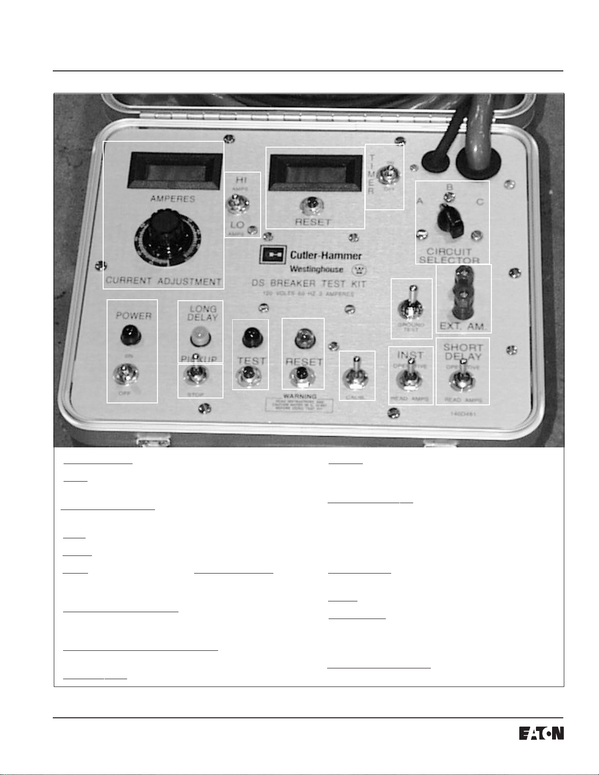
2.1.1 TESTKITCONTROLS(SEE FIGURE1)
The following are the identifications and fuctions of the
Test Kit controls. Any time these are referred to in the
following portions of this publicaiton they will be in italics
and underlined as shown in the following definitions of the
functions.
POWERON/OFF
–Turns on powerto theTestKit.
STOP
– This switch manually cuts offthe test current to
the Trip Unit.
LONGDELAYPICKUP
-Thislightisnotfunctionalfor
MagnumDStrip units.
TEST
– Starts the test.
RESET
–ResetstheTest Kit afteratest.
CALIB
–Usedinconjunctionwith
CURRENTADJUST
allowing for setting a pre-determined current level prior to
a test.
INSTOperative / Read Amps
–Fortesting the Instanta-
neousfunctionon AmptectorTripUnits.(Not functional
withMagnumDS trip units.)
SHORTDELAYOperative/Read Amps
–Fortestingthe
ShortDelay function.
GROUNDTEST
– For testing the Ground Fault function.
EXT.AM
– Allows for connection of an external ammeter
to read current levels. Jumper must be installed when not
usingexternalammeter.
CIRCUITSELECTOR
-PermitscheckingofallTripUnit
phaseinputcircuits.Sinceallfeed into a common pickup
andtiming circuit, it isonly necessary to use one phase to
test all the solid state circuitry functions. It is only neces-
sary to use one circuit function (e.g., long delay pickup) to
verify that each phase (A, B, and C) performs similarly.
TIMERON/OFF
–The timer isusedtocalculateand display
the time-delay functions of theTrip Unit.
RESET
(Timer) - Resets the timer after a test.
HI / LO AMPS
– Selects the “level” of current to be in-
jected. (LOAMPS is typicallyforchecking Long Delay
PickuporGroundFaultPickup,and HIAMPSis forchecking
ShortDelay PickuporInstantaneous Level)
CURRENTADJUSTMENT
–Adjuststhesecondarycurrent
injected into theTrip Unit.
2.1.2 TESTKIT ADAPTER
TheMagnum DSTestKitAdapter (8779C02G04) isusedto
connecttheTest Kit’s11-pinplugtotheMagnumDS
Digitrip Trip Unit 14-pin test port. In additon, the Auxiliary
PowerModule (PRTAAPM),whichispermanently con-
nected to the Adapter, must be connected to a 120V, 50/
60 HZ source to supply control power to theTrip Unit.(see
Figure2)
2.1.3 ZONE INTERLOCK SHORTING PLUG
TheZoneInterlockShorting Plug (8779C02G06) is
requiredwhenthebreakeris removed from the switchgear
cell for testing.The Shorting Plug must be installed on the
breakersecondarycontacts to defeat zone-interlock
wiring.(seeFigure3)
2.1.4 TEST KIT OPERATION GUIDELINES
To minimize thermal stress on theTest Kit andTrip Unit,
hold
CALIB
(momentary)toggle switch for no more than15
to 20 seconds at a time.
Ifcurrent persists after the testis complete, use
STOP
switch to turn off the current.
When checking settings on theTrip Unit, the general
procedure is to start with the high current settings and
work down to the lowest current setting. This avoids
unnecessarydialchanges after calibration.

I.L. 32-693 A
Page4
Effective September 1998
The output current is a function of the line voltage, which
mustbesinusoidaland have good regulation.
If the Test Kit
RESET
lamp will not light, check to make
sure that no trip LED’s are lit on theTrip Unit. If so, press
the “trip reset” pushbutton on the face of the Trip Unit.
2.2 CIRCUITBREAKERINFORMATION
2.2.1 TRIPUNITTOLERANCEBANDS
Long DelayTimes of the Trip Unit are top of band,
thereforeexpect shorter times whentesting.
Short Time, Instantaneous, and Ground Fault values
are mid-band, which have +/- 10% tolerance.
2.2.2 TRIPUNITTESTGUIDELINES
Testing of the Trip Unit must be performed with the Trip
Unitproperlyinstalled inthebreaker.
The long time function has a memory circuit with a reset
time of 36 times the long delay time setting;i.e., for a LDT
settingof4 seconds the reset timeis144 seconds (36x4).
Therefore, for long delay time tests, there must be a time
delay greater than the calculated reset time or the ac
control power to the Trip Unit must be interrupted between
tests to clear the memory circuit.To do this, remove the ac
supplytotheAuxiliaryPowerModuleratherthandiscon-
necting the plug from theTest Kit Adapter.A thermal
memory jumper may need to be repositioned to the
“inactive”position to disable the thermal memory.This
jumper is shipped from the factory in the “active” position.
If a trip function LED on the Trip Unit is lit prior to a test,
press the “trip reset”pushbutton on theTrip Unit.
Whenbench testing a breaker wired forzone interlock
applications,shortingplug 8779C02G06mustbeinstalled
per Figure 5.
SECTION 3: CHECKINGTHETEST KIT
3.1 GENERAL INFORMATION
This check should be performed when theTest Kit is first
received, or for a maintenance check. A more rigorous
check would be to perform all Trip Unit tests on a standard
Trip Unit.
3.2 HARDWARE CONNECTIONS (REFERTO FIGURE 2)
1. Connect the 11-pin banana plug on theTest Kit to the
correspondingport on theTest Kit Adapter.
2. Connect the 14-pin plug from theTest Kit Adapter into
the corresponding test port on theTrip Unit.
3.3 SETTINGTHETESTKIT
1.
TIMERON/OFF
switchto“OFF”.
2.
HI/LO AMPS
switch to“LOAMPS”.
3.
CURRENTADJUSTMENT
to“ZERO”.
3.4 TESTINGTHETESTKIT
1. PlugtheAPMand theTest Kit into 120 volt,60Hz
source.(Test Kit can be used on 50 Hz but timer
readings must be multiplied by 6/5.)
2. TurntheTestKit
POWERON/OFF
switch“ON”.
2A.
POWERON/OFF
pilot lamp(red)shouldlight.
2B.
RESET
pilotlamp(amber)shouldlight.If
RESET
pilot
lampisnotlit, push
RESET
button.
RESET
pilotlamp
shouldthenlight.
3. Turn
TIMERON/OFF
switchto“ON”.Timer should not
run.
4. Push
TEST
button.
4A.
TEST
pilot lamp (red) should light.
4B.
RESET
pilotlamp(amber)shouldgoout.
4C.
TIMER
should operate,countingseconds.
5. Operate
STOP
toggleswitch(momentary)to“STOP”.
5A.
TIMER
shouldstop.
5B.
RESET
pilotlamp(amber)shouldlight.
5C.
TEST
pilot lamp (red) should go out.
6. Pushmanual
RESET
buttonon timer.
TIMER
should
reset to zero.
7. Hold
CALIB
toggleswitch (momentary)in“CALIB”
positionandturn
CURRENTADJUSTMENT
knobfrom
zero to maximum. Ammeter should read from zero to
approximately8amperes.

I.L. 32-693 A
Page5
Effective September 1998
Note:If current reading remains at zero, check to see
thattheshorting baris across“EXT AM”Terminalsand
that the terminals are tight. If the shorting bar is
missing a substitute can be made using #10 wire and
spadeterminals.
8. ReturnCURRENT ADJUSTMENT knob to “ZERO”.
9. Note:This stepshould be performed withthe breaker
in the open position. If the main contacts are closed,
the breaker will trip open
.
9A. Put
HI/LOAMPS
switch in “HIAMPS”position. Hold
CALIB
toggleswitch (momentary) in“CALIB”position
andturn
CURRENTADJUSTMENT
knobfromzeroto
maximum. Ammeter should read from zero to ap-
proximately50 amperes.
10. If anyoftheabove checks do not function as intended,
operatethe
STOP
switchand
RESET
buttonand
repeat the check. If the situation persists, contact
Cutler-Hammer.
SECTION4:TESTINGTHETRIPUNIT
4.1 LEGEND
In=Rating PlugValue (must match Sensor Rating,Is)
Ig=GroundFault Current Pickup(SeeTable1)
It= Test Kit Trip Current
In/s = In/ Is
Ipu =Trip Unit Dial Setting
Ir=LongDelayPickup xShortDelayPickup
4.2 GENERALSETUP
1. HardwareConnections(referto Figure 2):
1A. Connectthe 11-pin bananaplug on theTest Kitto the
correspondingport on theTestKit Adapter.
1B. Connect the 14-pin plug from theTest Kit Adapter into
the corresponding test port on theTrip Unit.
2. PlugtheAPMand theTestKitinto 120 volt,60 Hz
source.(Test Kit can be used on 50 Hz but timer
readings must be multiplied by 6/5.) The green“Unit
Status”LED shouldflashindicatingthattheTrip Unit is
operational.
3. Turn theTestKitPOWERswitch“ON”.
4. It is recommended that a check of theTrip Unit per
Section 4.3 below be performed prior to performing
any of the other tests.
4.3 CHECKINGTHETRIPUNIT
1. Remove the ac supply from the Auxiliary Power
Module.
2. Set theTest Kit as follows:
2A.
TIMERON/OFF
switchto“OFF”.2 .
HI-LO
switch to“LO
AMPS”.
2C.
CURRENTADJUSTMENT
to“ZERO”.
3. Push
RESET
buttonandthenthe
TEST
button.
4. Slowlyincreasecurrentvia
CURENTADJUSTMENT
knobuntilgreen“UnitStatus”LEDlocatedonupperleft
hand comer ofTrip Unit starts to flash.This must
occur at 1.8 amperes or less to indicate that theTrip
Unitisfunctional.
5. ReconnecttheAPM totheacsupply.
4.4 CHECKINGLONGDELAYPICKUP(L.D.P.U.)
1. SetTest Kit as follows:
1A.
TIMER
switchto“OFF”.
1B.
HI-LO
switchto“LOAMPS”.
1C.
CIRCUITSELECTOR
switchto“A”.
1D.
CURRENTADJUSTMENT
to“ZERO”.
2. Set the long delay setting onTrip Unit to desired
setting.
3. Push
RESET
buttonandthenthe
TEST
button.
4. Slowlyincreasecurrentvia
CURRENTADJUSTMENT
knobuntil the“Unit Status”LED onTrip Unit starts to
flashquickly.Thisshould occurat the pickupcurrent,
which will be the long delay setting of theTrip Unit
times 5 amperes (+/- 10%). The rate of flashing will
slow to normal when the current is lowered below the
pickupsetting. NOTETHATTHELONGDELAYPICKUP
LAMPONTHETESTERWILLNOTLIGHT.
5. Use
STOP
switchto cut off current.
6. Repeat3and4withthe
CIRCUITSELECTOR
switchon
“B”and then on “C”.(See section 2.2.2 regarding the
Trip Unit’s thermal memory circuit)

I.L. 32-693 A
Page6
Effective September 1998
3. Set the Test Kit as follows:
3A.
TIMER
switch to “OFF”.
3B.
CURRENTADJUSTMENT
to“ZERO”.
3C. Set
HI-LO AMPS
switch to “HI AMPS”.
4. Push
RESET
button.
5. Toggle
CALIB
switch in “CALIB”position and using the
CURRENTADJUSTMENT
knob,setcurrenttoabout3/4
ofpickupsetting.(Donotholdinthe“CALIB”position
formore than 15 –20 seconds)
6. Push
TEST
buttonandincrease current steadily, using
CURRENTADJUSTMENT
knob,untilthebreakertrips
and redTest lamp goes out.
7. Priortoreturning
CURRENTADJUSTMENT
to“ZERO”,
hold
CALIB
switchin “CALIB” positionmomentarilyto
read the trip current.
4.7 CHECKINGSHORT DELAYPICKUP (S.D.P.U.)(IF
APPLICABLE)
1. SetTrip Unit Short DelayTime to minimum (.1 sec.)
andInstantaneoustooff.
2. SetdesiredShortDelayPickupontheTrip Unit.Note
that the Short Delay Pickup (Ir) is the product of the
LongDelay SettingtimestheShort DelayPickup
Setting.
3. Set theTest Kit as follows:
3A.
SHORTDELAY
switchin“OPERATIVE”position.
3B.
CURRENTADJUSTMENT
to“ZERO”.
3C.
TIMER
to“OFF”.
3D. Set
HI-LO AMPS
switch to“LOAMPS”ifShortDelay
Pickup is less than 8 amperes or to “H I AMPS” if it is
greater than 8 amperes.
4. Push
RESET
button.
5. Toggle
CALIB
switchin“CALIB”positionandusingthe
CURRENTADJUSTMENT
knob,setcurrenttoabout3/4
ofpickupsetting.(Donotholdinthe“CALIB”position
formore than 15 –20 seconds)
6. Push
TEST
buttonandincrease current steadily, using
CURRENTADJUSTMENT
knob,untilthebreakertrips
andred
TEST
lampgoesout.
7. Priortoreturning
CURRENTADJUSTMENT
to“ZERO”,
hold
CALIB
switchin “CALIB” positionmomentarilyto
read the trip current.
4.5 CHECKING LONG DELAYTIME (L.D.T.)
(SEE SECTION 2.2.2 REGARDING THETRIP UNIT’STHERMAL MEMORY
CIRCUIT)
1. Set theTest Kit as follows:
1A.
TIMER
switch to “OFF”.
1B.
HI-LO AMPS
switch to “HI AMPS”.
1C.
CIRCUIT SELECTOR
switch to “A”.
1D.
CURRENTADJUSTMENT
to“ZERO”.
2. If equipped, set Short Delay and Instantaneous
Pickups onTrip Unit to maximum (or off) to prevent
trip of the breaker by these functions.
3. Set desired Long Delay Pickup and Long DelayTime
onTripUnit.
4. Toggle
CALIB
switch to “CALIB”position and increase
currentontester,using
CURRENTADJUSTMENT
,to6X
LDPUcurrent setting. (Donotholdin the “CALIB”
positionformore than 15 –20 seconds)
5. Push
RESET
button.
6. Turn
TIMER
“ON”. IfTIMERdoesnotreadzero,push
manual
RESET
buttonon
TIMER
.
7. Push
TEST
button.
TIMER
willstopwhenTripUnit trips
the breaker.Timer should read less than the dial
setting but not under 2/3 of the setting;e.g., if set at
24,it should be morethan 16 seconds butless than 24
seconds.NOTE:I2t= CONSTANT,therefore,trip time
at a current other than 6 (In) is calculated as follows:
(6 / z)2X (Long Delay Time) =Trip Time at z current,
where z = multiples of LDPU at which test current is
applied. Example:LongDelayTimeSetting = 24
seconds. Thenfor3times LDPU current setting
applied, the Long DelayTripTime would be as fol-
lows:
(6 / 3)2X (24 seconds) = 96 second Long Delay Time
at3LDPU.Remember touse5amperestimes LDPU
setting to set the tester current.
4.6 CHECKINGINSTANTANEOUS(IFAPPLICABLE)
1. SetLongDelay Pickup and Timetomaximumandset
ShortDelayPickuptoM1setting,sothatthesefunc-
tions do not trip the breaker.
2. Set desired Inst.pickup on theTrip Unit. Note:Pickup
settingshouldnot exceedthe capabilityoftheTest Kit
(approx.50amperes).

I.L. 32-693 A
Page7
Effective September 1998
10. Push
TEST
button.
TIMER
willgive anapproximate
reading of the delay.
Note:This is not accurate enough
for close timing of short delay but, it will show the
differencebetweenthe band calibrations
.
11. RemovetheZoneInterlockDefeatadapter,and repeat
the test. Time delay should read minimal.
4.9 CHECKINGGROUNDPICKUP(IF TRIPUNITISSO
EQUIPPED)
1. SetdesiredGround FaultPickuponTrip Unit.
2. Set theTest Kit as follows:
2A.
HI-LOAMPS
switchto“LOAMPS”.
2B.
CURRENTADJUSTMENT
to“ZERO”.
2C.
TIMER
to“OFF”.
3. Push
RESET
button.
4. Hold
GROUNDTEST
momentaryswitchindown
positionduringsteps 5 and 6.
5. Push
TEST
button.
6. Increase
CURRENTADJUSTMENT
slowlyuntilthe
breaker trips.
7. Priortoreturning
CURRENTADJUSTMENT
to“ZERO”,
hold
GROUNDTEST
switchinthe downpositionand
CALIB
switchin“CALIB”position to read the trip
current.
8. For pickup values seeTable 1 below.
Note that the
pickupvaluesshownontheTest Kit are insecondary
amperes.To convert theTest Kit reading to primary
values, multiply ammeter readings by
In
/ 5
.
(1)Examples:
(a) Assume It= 1.2amps, In= 200, pickup setting =
.25, then: Ig= 1.2 x 200/5 = 48 primary amperes.
Table 1 shows expected value of 1.25 amperes.1.2
amperes is within the + 10% tolerance.
Forreferencepurposes,Table2 shows primary
GroundFaultamperes
Note:Expectincreasedpickup currents due to the
requiredsensorexcitingcurrent.
4.8 CHECKING SHORT DELAYTIME (IF APPLICABLE)
Note: ZoneSelective Interlocking essentiallydisables
ShortDelayTime. This function is provided asa
standard feature on all MagnumTrip Units. To test the
ShortDelayTime when the breaker is removed
beyondthe test position intheswitchgear,the zone
interlock shorting plug must be utilized (see Figure 5).
Without this, all Short Delay Time values will be
minimum.
1. DialShortDelayandLong DelayPickuponTripUnitas
desired.
Note:2.5 timesthe short delay pickup setting
shouldnot exceedthecapability of theTestKit
(approx. 50 amperes)
. i.e. Maximum short delay
pickup (Ir)= 4. Note that the Short Delay Pickup (Ir) is
afunctionof the Long Delay Setting times theShort
DelayPickupsetting.
2. SetLong Delay Time to maximum,andInstantaneous
“off”, so that these functions do not trip the breaker.
3. Ifthebreakersecondarycontacts are not connected to
theswitchgear Zone Interlock wiring (breaker is
beyondthetestposition), install the Zone Interlock
Defeatadapter.
4. Set theTest Kit as follows;
4A.
TIMER
switchto“OFF”.
4B.
HI-LOAMPS
switchto“HIAMPS”.
4C.
CURRENTADJUSTMENT
to“ZERO”.
5. Togglethe
CALIB
switchto“CALIB”positionandadjust
current,using
CURRENTADJUSTMENT
knob,to2.5
timespickup setting. Note that if thebreaker is closed,
it will trip. Do not reclose the breaker until the test
current is adjusted to the proper value.
6. ResetTrip Unit by pressing the“trip reset”pushbutton
on theTrip Unit.
7. Closethebreaker.
8. Turn
TIMER
“ON”. If
TIMER
doesnotreadzero,push
RESET
(Timer) button.
9. Push
RESET
button.

I.L. 32-693 A
Page8
Effective September 1998
4.10 CHECKING GROUND DELAYTIME
Note: ZoneSelective Interlocking essentiallydisables
GroundDelayTime. Thisfunctionisprovidedasa
standard feature on all MagnumTrip Units. To test the
GroundDelayTimewhen the breaker is removed
beyond the testposition in the switchgear, the zone
interlock shorting plug must be utilized (see Figure 5).
Withoutthis,allGroundDelayTime values will be
minimum.
1. Setdesired Ground FaultTime setting onTrip Unit.
2. Set the Test Kit as follows:
2A.
TIMER
to“OFF”.
2B.
CURRENTADJUSTMENT
to“ZERO”.
2C.
HI-LOAMPS
switchto“LOAMPS”.
3. Ifthebreakersecondarycontacts are not connected to
theswitchgear Zone Interlock wiring (breaker is
beyondthetestposition), install the Zone Interlock
Defeatadapter.
4. Whileholdingthe
GROUNDTEST
momentaryswitch
andthe
CALIB
switch in the down positions,turn
CURRENTADJUSTMENT
knobtogetacurrentabove
pickup value (seeTable 1 and Step 8 of section 4.9
above).
Note that if the breaker is closed, it will trip.
Do not reclose the breaker until current is adjusted to
thedesiredvalue.
5. Release
CALIB
and
GROUNDTEST
switches.
6. ResetTrip Unit by pressing the“trip reset”pushbutton
on theTrip Unit.
7. Closethebreaker.
8. Turn
TIMER
“ON”. IfTIMERdoesnotreadzero, push
manual
RESET
(Timer) button.
9. Push
RESET
button.
10. Whileholding
GROUNDTEST
momentaryswitchinthe
downposition, push the
TEST
button.Timer will give
an approximate reading of the delay.
11. Remove the Zone Interlock Shorting Plug, and repeat
the test. Time delay should read minimal.

I.L. 32-693 A
Page9
Effective September 1998
Table 1 - Ground Fault Current Pickup Settings (Test Kit Display Amperes)
Installed
RatingPlug
Amperes (In) .25 .30 .35 .40 .50 .60 .75 1.0
100 1.25 1.50 1.75 2.00 2.50 3.00 3.75 5.00
200 1.25 1.50 1.75 2.00 2.50 3.00 3.75 5.00
250 1.25 1.50 1.75 2.00 2.50 3.00 3.75 5.00
300 1.25 1.50 1.75 2.00 2.50 3.00 3.75 5.00
400 1.25 1.50 1.75 2.00 2.50 3.00 3.75 5.00
600 1.25 1.50 1.75 2.00 2.50 3.00 3.75 5.00
800 1.25 1.50 1.75 2.00 2.50 3.00 3.75 5.00
1000 1.25 1.50 1.75 2.00 2.50 3.00 3.75 5.00
1200 1.25 1.50 1.75 2.00 2.50 3.00 3.75 5.00
1600 1.25 1.50 1.75 2.00 2.50 3.00 3.75 3.75
2000 1.25 1.50 1.75 2.00 2.50 3.00 3.00 3.00
2400 1.25 1.50 1.75 2.00 2.50 2.50 2.50 2.50
3200 1.25 1.50 1.75 2.00 2.00 2.00 2.00 2.00
4000 1.25 1.50 1.50 1.50 1.50 1.50 1.50 1.50
5000 1.20 1.20 1.20 1.20 1.20 1.20 1.20 1.20
Table 2 - Ground Fault Current Pickup Settings (Primary Amperes)
Installed
RatingPlug
Amperes (In) .25 .30 .35 .40 .50 .60 .75 1.0
100 25 30 35 40 50 60 75 100
200 50 60 70 80 100 120 150 200
250 63 75 88 100 125 150 188 250
300 75 90 105 120 150 180 225 300
400 100 120 140 160 200 240 300 400
600 150 180 210 240 300 360 450 600
800 200 240 280 320 400 480 600 800
1000 250 300 350 400 500 600 750 1000
1200 300 360 420 480 600 720 900 1200
1600 400 480 560 640 800 960 1200 1200
2000 500 600 700 800 1000 1200 1200 1200
2400 600 720 840 960 1200 1200 1200 1200
3200 800 960 1120 1200 1200 1200 1200 1200
4000 1000 1200 1200 1200 1200 1200 1200 1200
5000 1200 1200 1200 1200 1200 1200 1200 1200
(1) For the Digitrip 1150, settings are non-discrete, and may fall between the values listed above. The corresponding pickup
values must then be calculated. (Igx In, max 1200A)
(2) Except as noted, tolerances on pickup levels are ± 10% of values shown in chart.
PickupSetting(Ig)(1) andCorrespondingPickupLevels (Secondary Amperes) (2)

I.L. 32-693 A
Page10
Effective September 1998
Figure1.TestKit Controls and Legend
1
POWER ON/OFF
– Turns on power to the Test Kit.
2
STOP
– This switch manually cuts off the test current to
the Trip Unit.
3
LONG DELAY PICKUP
- This light is not functional for
Magnum DS trip units.
4
TEST
– Starts the test.
5
RESET
– Resets theTest Kit after a test.
6
CALIB
– Used in conjunction with
CURRENT ADJUST
allowing for setting a pre-determined current level prior to a
test.
7
INST Operative / Read Amps
– For testing the Instanta-
neous function on Amptector Trip Units. (Not functional with
Magnum DS trip units.)
8
SHORT DELAY Operative / Read Amps
– For testing the
Short Delay function.
9
GROUND TEST
– For testing the Ground Fault function.
12
3
4
5
67
77
8
9
10
11
12
13
14
15
10
EXT.AM
– Allows for connection of an external ammeter
to read current levels. Jumper must be installed when not
using external ammeter.
11
CIRCUIT SELECTOR
- Permits checking of all Trip Unit
phase input circuits. Since all feed into a common pickup and
timing circuit, it is only necessary to use one phase to test all
the solid state circuitry functions. It is only necessary to use
one circuit function (e.g., long delay pickup) to verify that
each phase (A, B, and C) performs similarly.
12
TIMER ON/OFF
– The timer is used to calculate and
display the time-delay functions of the Trip Unit.
13
RESET
(Timer) - Resets the timer after a test.
14
HI / LO AMPS
– Selects the “level” of current to be
injected. (LO AMPS is typically for checking Long Delay
Pickup or Ground Fault Pickup, and HI AMPS is for checking
Short Delay Pickup or Instantaneous Level)
15
CURRENTADJUSTMENT
– Adjusts the secondary current
injected into the Trip Unit.

I.L. 32-693 A
Page11
Effective September 1998
SECTION5:FIGURESANDTABLES
Figure 2.Test Kit and Adapter Figure 3.Zone Interlock Shorting Plug
Figure4.TripUnit FacePlate ShowingTestPort Connec-
tion Figure 5.Zone Interlock Shorting Plug Installed on Circuit
Breaker.

Thisinstructionbookletis published solely for information purposes andshouldnotbeconsidered all inclusive. If further
informationis required, youshouldconsultCutler-Hammer.
Saleof product shown in thisliterature is subject to termsand conditions outlined in appropriateCutler-Hammer selling
policies or other contractual agreement between the parties. This literature is not intended to and does not enlarge or
addtoany such contract. The solesourcegoverning the rights and remedies ofanypurchaser of this equipment isthe
contractbetweenthe purchaser and Cutler-Hammer.
NOWARRANTIES,EXPRESSEDORIMPLIED,INCLUDINGWARRANTIESOFFITNESSFORAPARTICULARPURPOSE
ORMERCHANTABILITY,ORWARRANTIESARISINGFROMCOURSEOFDEALINGORUSAGEOFTRADE,AREMADE
REGARDINGTHEINFORMATION,RECOMMENDATIONSANDDESCRIPTIONSCONTAINEDHEREIN.Innoeventwill
Cutler-Hammer be responsible to the purchaser or user in contract, in tort (including negligence), strict liability or
otherwiseforanyspecial, indirect,incidentalor consequential damage or loss whatsoever,includingbutnot limited to
damage or loss of use of equipment, plant or power system, cost of capital, loss of power, additional expenses in the use
of existing power facilities, or claims against the purchaser or user by its customers resulting from the use of the infor-
mation,recommendationsand descriptions contained herein.
Page12
I.L. 32-693 A
Cutler-Hammer
221 Heywood Road
Arden, NC 28704
Effective September 1998
Printed in U.S.A./CCI
This manual suits for next models
3
Table of contents
Other Eaton Test Equipment manuals

Eaton
Eaton CEAG AT-S+ Series Service manual

Eaton
Eaton MET User manual

Eaton
Eaton Xiria User manual

Eaton
Eaton IZM6-TEST-KIT User manual

Eaton
Eaton DILM32-XMAN Manual

Eaton
Eaton ZSI User manual

Eaton
Eaton VCP-W User manual

Eaton
Eaton Sefelec RXS50 User manual

Eaton
Eaton MTK2000 Manual

Eaton
Eaton SEFELEC 5 Series User manual
Popular Test Equipment manuals by other brands

Alcolock
Alcolock V3 B-2 Series Service guide

ULTIMATE SPEED
ULTIMATE SPEED KH 4103 manual

PCE Health and Fitness
PCE Health and Fitness PCE-950 user manual

Com-Power
Com-Power LI-3100 instruction manual

bonitron
bonitron M3628PCF Customer Reference Manual

National Semiconductor
National Semiconductor DP8390 manual