Amptec Research 620VN Manual

Explosive Safety Igniter Tester
AMPTEC 620VN
OPERATION/MAINTENANCE MANUAL
AUSTIN, TEXAS 78759 USA CAGE CODE 1CRL2
PHONE +001 (512) 858-4045 or 1-800-350-5105 (from the USA)
FAX +001 (512) 3858-4340 or 1-800-430-5440 (from the USA) website http://www.amptec.com
Preliminary Manual Revision A 10APR2013

A MESSAGE FROM THE PRESIDENT
We at AMPTEC RESEARCH would like to thank you, our customer, for selecting the
AMPTEC 620VN Failsafe Igniter Tester/ Digital Ohmmeter. Over the past 36 years our experienced
engineering staff have designed, manufactured and supplied earlier versions similar to
the Model 620 and 620 Series Igniter Testers to the U.S. NAVY for the “TOMAHAWK CRUISE
MISSILE”, and the Evolved Sea Sparrow Missile (ESSM), the U.S. ARMY for the “STANDARD
MISSILE”, the U.S.A.F. for the AIM-9 “ SIDEWINDER”, AIM-7 “SPARROW” and AIM-120
“AMRAAM” just to name just a few. We value the trust our customers have placed with us, and are looking
forward to supporting any new requirement you may have ....
Kerry Clark - President AMPTEC RESEARCH
U.S. N.I.ST. CALIBRATION CERTIFICATE
AMPTEC RESEARCH, Inc. certifies that this instrument has been completely tested
and inspected and found to meet published specifications as found in this manual on
the date stated on the attached N.I.S.T. Certificate. AMPTEC RESEARCH,
Corporation further certifies that its calibration measurements are traceable to the U.S. National Institute of
Standards and Technology.
620VN SERIES IGNITER TESTER WARRANTY
Permission and a return authorization (RMA) number must be obtained directly from
AMPTEC’s customer service department (via phone, FAX, or email) for repairs
(warranty or otherwise). We need to issue you an RMA number so we can keep track of the instrument and
it’s owner (i.e. who to contact). The warranty period for this instrument is 1 year from when it was first
shipped. AMPTEC RESEARCH will repair or replace the instrument during the warranty period provided
it is returned to AMPTEC RESEARCH, freight prepaid. No other warranty is expressed or implied. We
are not liable for consequential damages. No liability will be accepted if returned without such permission.
Some AMPTEC products may have their design frozen, and no changes will be made without prior notice to
the proper approving authority. Through out this manual, there is reference made using to the generic model
620 series Igniter Testers. There are any versions of the 620 Igniter Tester specifically developed to meet
our customers requirements. The specification, operation, drawing and schematic sections of this manual
contain the unique detail that define the AMPTEC 620VN. Due to continuing product refinement, due to
possible parts going obsolete and other component manufacturer changes, AMPTEC RESEARCH reserves
the right on rare occasions to change any of its products specifications.
R M A
page 1

TABLE OF CONTENTS
SECTION A: RECEIVING AND INITIAL INSPECTION
A-1 Introduction to the AMPTEC 620VNS Igniter Tester
A-2 Receiving, Unpacking, and Initial Inspection
A-3 Setup and Use
SECTION B: 620VN FAILSAFE OHMMETER SPECIFICATIONS
B-1 Specifications
SECTION C: REPLACEMENT, OPTIONAL AND ACCESSORY ITEMS
C-1 Available Accessories and Options
SECTION D: OPERATION, FUNCTION AND USE
D-1 General
D-2 Front Panel
D-3 RS232C Computer Control and Command Set
D-4 4-Wire Resistance Measurement
D-5 Connections
SECTION E: GENERAL OPERATION AND DESIGN
E-1 General
E-2 Troubleshooting
E-3 Circuit Descriptions
E-4 Analog-to-Digital Converter
E-5 Ohms-to-DC Converter
page 2

E-6 Failsafe Design
E-7 Ultra-Safe Power Supply Scheme
Figure E-1. Model 620VN Block Diagram
Figure E-1B Analog-to-Digital Converter Timing Diagram
Figure E-2 Analog Section of IC1 and IC2
Figure E-3. Constant Current Source Diagram (Simplified)
Figure E-4. LED Display Pin Functions
SECTION F: ROUTINE MAINTENANCE
F-1 General
F-2 Required Test Equipment
F-3 Calibration Procedure
SECTION G: SCHEMATICS AND DIAGRAMS
Drawing 620VN -070 620RMS Main PCB Electrical Schematics
(Rev E Main PCB) 620RMS-070 DVM1 - 1of 2
and 620VL-070 Current (I source - 2 of 2) Source}
620VN Main PCB Bill Of Materials (components parts list) page 1 of 2
620VN Main PCB Bill Of Materials (components parts list) page 2 of 2
Drawing 620VN-600 620VN Main PCB Assembly (Silkscreen Ref. Design Dwg. ) rev. J
Drawing 620VN-RS232 620VN Rear Panel Diagram
Drawing RS232C Controller PCB Schematic ( page 1 of 3 pages)
Drawing RS232C Controller PCB Schematic ( page 2 of 3 pages)
Drawing RS232C Controller PCB Schematic ( page 3 of 3 pages)
620VN (sample) Quality Inspection Test Report
R109
10K
IC101
5
6
+
-
R105
18.2K
R107
10K
RV102
1K OHM
POT
R108
10K
page 3

A-1. Introduction to the AMPTEC 620VN
Some of the devices the 620VN Igniter Tester may
be used on include: fuses, squibs, igniters,
explosive bolts, rocket motor squibs, automobile
air-bag initiators and many others.
The AMPTEC 620VN is a 4-wire failsafe digital
ohmmeter which has been designed to reliably
use very low test currents for its resistance
measurement. Failsafe Output Circuitry
proprietary to AMPTEC RESEARCH ensures
that test current levels do not exceed the
specified "failsafe current" even in a worst-case
component failure situation. The failsafe feature
is tested in every instrument before shipment.
The 620VN uses the same main printed circuit
board (PCB) as all of the AMPTEC 620A Igniter
Testers. The 620VN has many features (no
resistance range gaps form 20 ohms to 2.0
megohms) which make it useful in a variety of
applications. Please check the last chapter of this
manual for addendums that may apply to the
AMPTEC 620VN .
For added safety the AMPTEC 620VN Igniter
Tester is always electrically isolated or
electrically "floating". It normally comes
configured with the 2 stage option “247”
Isolated Continuous Operating power. The first
stage of isolation with op “247” is the ACV wall
adapter (ie 120 VAC input to 24 VDC output).
This provides the first stage of initial high
frequency and high voltage (transient)
suppression.
(OP 247 ) The second stage of isolation uses,
converts, isolates and conditions the +24 VDC
coming into the meters rear panel. The rear
panel input voltage (+24 VDC) is converted (via
several circuits) using a Medical Grade DC to
DC convertor into the +5.0 VDC that provides
the meters main operating power. The high
quality Medical grade DC to DC Convertor uses
essentially transformer isolation and voltage step
down principals to provide the meters main
power as a “floating” +5VDC. A 3000 VAC
Isolation (Hipot) Test Report is available from
AMPTEC’s engineering department that has
established the isolation of the 2 stage “OP247”
as being at least Isolated to the 3 KV level.
A-2. Receiving, Unpacking
and Initial Inspection
Should the AMPTEC shipping box appear
damaged upon arrival, request that the carrier's
agent (i.e. UPS) be present when the unit is
unpacked. If the 620VN appears damaged, the
carrier's agent should authorize repairs before
the unit is returned to the factory. Even if the
instrument appears undamaged, it may have
suffered internal damage in transit that may not
be evident until the unit is operated or tested to
verify conformance with its specifications.
If the unit fails to operate or
fails to meet the performance
specifications of Section B,
notify the carrier's agent and
the nearest AMPTEC Sales
Office. Retain the shipping carton for the
carrier's inspection. DO NOT return
equipment to AMPTEC RESEARCH or any
of its sales offices without first obtaining an
(RMA) Return Material Authorization number.
We need to know who to contact and how to
contact (i.e. phone number and FAX number) in
order to properly coordinate the return of the
repaired AMPTEC product.
Call AMPTEC RESEARCH first, prior to
just returning the 620VN . We can often
troubleshoot (based on the symptoms you
describe) and identify the problem. We may
possibly be able to fix the problem over the
phone and prevent you from having to return the
unit to AMPTEC for repair.
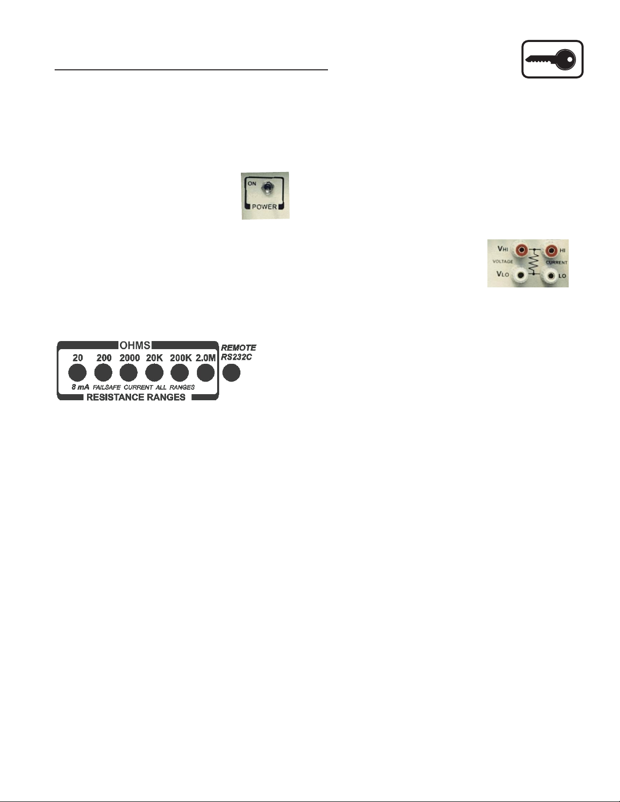
A-3. Setup and Use
The AMPTEC 620VN Igniter Tester may be
setup to operate within minute(s) of power "turn
on" (unless your in an extremely cold tempera-
ture - allow more time for warm-up - 15 min-
utes). A quick test lead integrity check and it
should be ready to use. The front panel will
display a negative or minus sign Avoid expos-
ing the AMPTEC 620VN Igniter Tester to
extremes of temperature which will affect accu-
racy.
SECTION A - RECEIVING AND INITIAL INSPECTION
R M A
page 4

Table B-1 Specifications
Accuracy: (for 1 year @25°C ± 10°C)
20 Ohm range - 20K Ohm ranges . . . . . . . . . . . . ±0.02% of reading ±0.02% of range
200K Ohm ranges . . . . . . . . . . . . . . . . . . . . . . . . ±0.02% of reading ±0.05% of range
2.0 MOhm ranges. . . . . . . . . . . . . . . . . . . . . . . .
Temperature Range
Operating 0°C to 50°C
Storage -10°C to 70°C
Temperature Coefficient
20 ohm through 200 ohm ranges ±0.002% per °C (from 0°C-15EC and 35°C-50°C)
2.0 Megohm range ±0.01% per °C (from 0°C-15EC and 35°C-50°C)
Instrument Display . . (20,000 count) 4½ digit Super Bright Light Emitting Diodes (LED)
Over-Range Indication . . . . . . . . . . . . . . . . ( select next higher range) 620VN Display flashes
Measurement Update Rate . . . . . Approximately 300ms
Open Circuit Current Source Compliance Voltage . . . . . clamped at ~1.6 volts
DC Power - The AMPTEC 620VN safety meter is normally configured with (2 Stage Isolation) OP247
Isolated Continuous Operating Power .
Remote Control Interface - The AMPTEC 620VN safety meter is normally configured with the option
“232” an optically Isolated Serial Interface. It that allows computer/controller to remotely send I/O
commands that make the 620VN change ranges to the desired range and give back resistance readings via a
rear panel RS232C interface/connector. See section in this manual for available I/O commands and format
detail.
Dimensions . . . . . . . . . . . . . . . . . . . . . . . . . . . . 9.0" (23cm) W x 9.0" (23cm) D x 3.0" (8cm) H
Weight . . . . . . . . . . . . . . . . . . . . . . . . . . . . . . 4 lbs net; 10 lbs shipping (without transit case)
± 1.0 % of reading ± 0.2% of range
AMPTEC 620VN EXPLOSIVE SAFETY
IGNITER TESTER - SPECIFICATIONS
620VN Resistance Range / Nominal Current/Failsafe Current
and Display Resolution Table
1 mW10 mW0.1 W
8 mA
5 mA 500 uA 50 uA 5 uA 0.5 uA 0.5 uA
8 mA 8 mA 8 mA 8 mA
8 mA
1 W10 W100 W
Resistance Range
Test Current
Fail Safe Current
Ohms Resolution
20W200W2000 W2 MW
20 KW200KW
Continuous Decade Resistance Ranges (No Gaps) from 20.0 Ohms to 2.0 Megohms Fullscale
page 5

AMPTEC RESEARCH accepts “VISA or MC” Credit Card
620A-4, 620BH, 620VL, 620VN etc. compatible
Phone +01 (512) 858-4045
FAX +01 (512) 858-4340
www.amptec.com Austin, TX USA 78737
All AMPTEC 620 series test lead and probe sets are a minimum 48" length,
dual banana termination at the ohmmeter end (call the Sales Department at
AMPTEC RESEARCH for any custom requirement).
Option "110" Test Lead Pouch (Mounted on the 620A4 top lid) with
enough storage room to hold a variety of test leads and accessories (see
photo above).
Option "300" Gold Plated Four Terminal Kelvin Clip Test Lead Set open
to ½" for connection to wires, lugs, etc.
Option "302" Gold Plated Banana Jack Backed Four Terminal Kelvin
Clips open to ½" for connection to wires, lugs, etc.
Option "401" Single Pointed Handheld Probe Set - ideal for probing into
recessed squib wire sockets, and onto larger metal surfaces (flat or round)
such as flares, rounds and shells, that do not easily accept test lead clip
attachment.
Option "403" 4 Terminal Kelvin Mini-probes - (photo shown above) Each
probe has two spring loaded, gold plated, steel tips with 0.18" separation.
(one red and one black handheld probe). Excellent general purpose Mini-
Probe, and along with the Option "300" Kelvin Clip Leads easily fit inside
the AMPTEC 620ES Test Lead Pouch (OP110).
Option “620-ISO” Isolated Analog Output provides an isolated DC
Voltage output directly proportional to the measured resistance (
1.2345 VDC =1.2345 ohms). A datalogger or system DVM can safely
measure the isolated voltage as being representative of the actual resistance
of the device under test.
Option "247" for continuous operation 24Hr/7day. Dual stage isolation
provides safe power for 620 series Igniter Tester to safely run continuous 24
Hrs/day without batteries. It’s proven “Medical Safety 3 KV Isolation”
technology is used in monitoring human patients wired to electrical
instrumentation. This field tested option is presently running in over 50
AMPTEC 620 series igniter testers in U.S. Anti-Ballistic Missile systems
(24Hrs/7).
Kelvin Leads, Probes Accessories and Options
Option “290” Alligator Test Lead Set
Option "300"
Kelvin Clip Test Leads
FED SWIFT delivery programEX
Option "403"
Kelvin Mini-probe
Test Lead Set
Option "302" Banana Jack
Backed Kelvin Clips
AMPTEC 620A series Test Leads, Probes and Accessories
See Option "247" Continuous Isolated
Operating Power capability description on
the bottom left column. Recommended for
customers that plan to automate the
AMPTEC 620 series Explosive Safety
Igniter Tester using the RS232C interface.
Option "100" is a hardshell (impact resistant plastic) shock
absorbing foam lined meter and accessory carrying case for the
620A series Ohmmeter with extra room for test leads, battery
charger, Kelvin Clip Test Leads, Connector Adapters, single
pointed probes and operator manual etc.
Option "519S and D" Rack Mount Adapter
Option "519S or D" - "S” for a single unit, “D” for dual/side by
side two unit install. The AMPTEC 620VN Igniter Tester (this
option comes with a flush panel mount faceplate cutout and
support tray) can be installed/secured into a standard 19" NEMA
equipment rack support tray (provided). The meters feet screws
(~ 3” long #6-32 machine screws) are routed through the
support tray holes back through the meter’s (bottom) feet holes
into its lid.
page 6

SECTION D - OPERATION, FUNCTIONAL
SELF - TEST AND USE
The AMPTEC 620VN ohms ranges can be
computer controller selected via the RS232C
interface (see rear panel).
Gold Plated Five way
Input Jacks
The AMPTEC 620 front panel input jacks are a
gold plated variety that readily accept a number
of user connection modalities. The unit's
banana post input jacks may be unscrewed
several turns to exposed a horizontal hole thru
the gold plated post. The AMPTEC 620 user can
directly connect a bare wire thru the banana post
(horizontal hole). The AMPTEC 620 front panel
input posts also accept wires with spade lugs,
and or banana jacks. The front panel or rear
panel terminal strip inputs are wire for Voltage
High and Voltage low , and Current high and
Current low (resistance measurements). The
spacing of the front panel jacks only allow
horizontal connection of the dual banana jack
test leads to prevent mis-connection (i.e. during
calibration) .
Calibration Access Screws
Recessed in the feet on the bottom side of the
AMPTEC 620VN meter there are 4 screws
(phillips type). When removed you can "remove
the lid" and access the main internal electronics
/PCB and calibration “adjustment potentiom-
eters. They (feet screws) are normally meant to
remain intact and to be removed by authorized
Repair and Calibration Lab staff.
If the resistance being measured (including
"Open Circuit/ Disconnected states") is a higher
value than the selected range, the instrument's
display will flash (blink) , which indicates
"overrange" . whichis also available via the
automated control RS232C Interface.
D-1. General Operation
This section contains operating instructions for
the AMPTEC 620VN Explosive Safety Igniter
Tester.
D-2. Front Panel Features and Operation
When the front panel power switch
is in the “OFF” position, all power
is removed from the unit’s main
PCB and the unit’s RS232C interface. When the
620VN main power switch is placed in the
power “ON” position, the unit powers up all
ohms and related measurement circuitry and
allows the optically RS232C interface located
on the unit’s rear panel to also operate remotely.
Resistance Range Switches
The 4 ½ digit display can display up to 19.999
ohms on the 20 ohm range and 199.99 ohms on
the 200 ohm range. The 2.0 Megohm range can
display resistance readings up to 1.9999
Megohms. The meter can display from readings
0000 to 19,999 (decimal point position varies
with the selected range). That is referred to as
20,000 counts, which is common for 4 ½ dight
meters. The user can depress (feel a “click”) one
of the meter’s range latching switches to select
the desired resistance range. The prior range
switch button will “pop out” when a new range
is selected.
The far right front panel switch labeled
“REMOTE RS232C” must be selected (clicked
in) to get the meter to accept remote commands
via the RS232C (rear panel) serial interface.
When the “REMOTE RS232C” mode is
selected all the meters manually selected
resistance range switches should “pop out” or
be de-selected. In this way, There is no manual
selected range and meter is ready to accept
remote RS232C computer commands for range
and reading control.
OFF
page 7

AMPTEC 620VN
620VN
620VN-501
620VLT-602
620VN
OP 24/7 DC
620VN-123
D-3 RS232C Computer Control and Command Set
750 mA
620VN Rear Panel with options RS232C I/O
The rear panel (shown above) may contain optional
jacks, terminals, labels, and stickers.
Item 1 -The option "247" Continuous Isolated
Operating Power DC Adapter (item #1) must be left
in the rear panel jack in order to continuously operate
the unit. For Safety Reasons - Only the AMPTEC
supplied AC/DC adapter, in conjunction with the
meter’s OP 247 internal DC/DC circuitry has been
tested and approved for its 3 KV isolation.
Item 2 is the fuse holder - replace with a 2 ampere 3
AG type fast blow fuse (rarely needs replacing).
RS232C Serial Interface - Item # 3 is the safety
isolated RS232C serial I/O (9 pin D type Sub-min
connector ). This RS232C Interface provides the
meter’s resistance measurements to a PLC fitted with
a serial port. The RS232C protocal settings should
be 9600 Baud, 8 Bits , No parity , 1 Stop Bit , 9 pin
D Sub-min connection.
RS232C Command Set (Option 232 )
(NOTE: All front panel range buttons must be de-
selected (press in half way) with all range
pushbuttons out in order to disable with local
lockout and enable RS232C control. Note commands
are case sensitive.
C Continuous Read Mode - RS232C I/O
outputs a data string every A to D conversion cycle,
approx. 2.5 times per second.
S Single Read Mode - RS232C I/O outputs
a single data string upon reception of a “R”
command.
R Read - Commands RS232C I/O to output a
single data string ( 1 resistance reading).
r0De-Selects all Ranges
r1 Selects the 20 Ohm Range
r2 Selects the 200 Ohm Range
r3 Selects the 2000 Ohm Range
r4 Selects the 20 K Ohm Range
r5 Selects the 200 K Ohm Range
r6 Selects the 2 Meg Ohm Range
VVersion commands board to output the firmware
version string.
Data Format - The RS232C I/O outputs a data string
with the following format:
1.2345E+3 The measurement is always in Ohms
+3
(where E+3 = 10 scientific notation style) . The
Exponent is defined below. 1.2345E+3 = 1.2345
+3
+3
KOhms (where E =10 ). 1.3700E+1 = 13.700 Ohms
+1
+1
(where E =10 )
Range Exponent
20.0 Ohm E+1
200.0 Ohm E+2
2000 Ohm E+3
20 KOhm E+4
200 KOhm E+5
2.0 M Ohm E+6
An overrange condition is indicated by
9.9999Enn..Where nn is the selected resistance range
exponent. A Range Error is indicated by x.xxxxERR.
Item # 4 is the unit’s serial number sticker.
Item # 5 is the 4 terminal rear terminal strip (they are
wired in parallel with the front terminals). If a “2 wire
ohms” connection is made then the V high and I high
terminals should be shorted together, and the V low and
I low terminals should be shorted. The 620VN Voltage
High, Voltage low, Current high and Current low wires
are permanently connected to the gold plated rear termi-
nal strip ( seel labeled terminal strip on rear panel).
Item #6 Calibration Sticker - If the calibration due
date has expired ( 1 year) AMPTEC or a Cal. Lab can
contacted to re-certify the AMPTEC 620VN Explosive
Safety Ohmmeter/Igniter Tester. contact AMPTEC
customer service 001-512-858-4045 . www.amptec.com
page 8

AMPTEC 620A series Explosive Safety Igniter Tester RS232C Operation
These instructions should provide a step-by-step how to operate a AMPTEC 620A series (620ES, 620BH, 620EH, 620VL,
620VN etc.) Explosive Safety Igniter Tester via the optically Isolated RS232C interface. An important note - all manual
selected push button front panel ranges must first be de-selected (popped out) prior to any RS232C remote operation.
The RS232C operation example(s) shown below is for an AMPTEC 620VL Igniter Tester. For the AMPTEC 620VN press
the meter’s front panel remote RS232 button to pop out any previous selected resistance ranges. The RS232 remote
control process is essentially the same for all 620A series meter. Newer PC controllers (i.e. Windows 7 etc.) may not come
with an RS232C serial port but do offer a USB port. There are many low cost USB to serial converter cables available
(see below - item 1 and 2).
1. Plug USB-to-serial interface cable into computer (if direct serial-to-serial connection is not available).
2. Plug serial end of USB-to-serial cable into the AMPTEC 620VN Igniter Tester unit.
3. Open serial communication software and select the correct communication channel.
4. Ensure that communication specifications are as follows:
·9600 bits per second.
·8 data bits.
·No parity bit.
·One (1) stop bit.
·No flow control.
5. Start testing each range of the unit via the RS232C interface by typing in the following commands (commands are
case sensitive):
·S
i. Should receive prompt “Single Read Mode Selected”.
ii.To have a reading displayed on the screen from Single Read Mode, type “R”.
·r1
i. Should receive prompt “20 Ohm Range Selected”.
·r2
·r3
·r4
i. Should receive prompt “200 K Ohm Range Selected”.
ii.This resistance range is valid for any resistance being measured that is less than 199.99 K Ohm.
·r6
i. Should receive prompt “2 M Ohm Range Selected”.
ii.This resistance range is valid for any resistance being measured that is less than 1.9999 M Ohm.
continued next page
·r0
I. All resistance ranges are “De-selected”.
ii.This resistance range is valid for any resistance being measured that is less than 19.999 Ohm.
i. Should receive prompt “200 Ohm Range Selected”.
ii.This resistance range is valid for any resistance being measured that is less than 199.99 Ohm.
i. Should receive prompt “2000 Ohm Range Selected”.
ii.This resistance range is valid for any resistance being measured that is less than 1999.9 Ohm.
i. Should receive prompt “20 K Ohm Range Selected”.
ii.This resistance range is valid for any resistance being measured that is less than 19.999 K Ohm.
·r5
page 9

6. If the commands above were entered and the correct prompt was not received, then type “V”. The correct prompt
from typing “V” is “620VN version 1.0 (C)opyright Amptec Research 3/16/2013”. If this prompt was not received,
then the firmware of the unit is out of date and must be updated. If the correct prompt was received, but the
commands in bullet 5 did not yield the correct prompt, then there is a defect in the unit.
7. If every command up to this point has yielded the correct prompt, then the unit is operating correctly. Other
commands available for this unit are:
·R
i. Should receive resistance reading displayed on screen corresponding to the range that the unit is
currently operating in.
ii.Must be in Single Read Mode to receive this command properly.
·C
i. Should receive prompt “Continuous Read Mode Selected”.
ii.This command continuously displays the resistance being measured. The only way to exit
Continuous Read Mode is to type “S” to enter into Single Read Mode.
If every command entered yielded the correct prompt(s) that were detailed above, then the unit is operating correctly. If
incorrect prompts were received, try repeating the command, or repeating the process listed in bullet 6.
For further information regarding the AMPTEC 620VN Explosive Safety Igniter Tester or any other AMPTEC product,
please contact us at:
Phone: (512) 858-4045
Email:
Website:
www.amptec.com
page 10

Jacks. All AMPTEC 620VN Kelvin leads have
the 4 wire current high, current low as well as
the voltage sense high and voltage sense low
routed to the end of the leads. The 4 wire Kelvin
wires then terminate in a pair of gold plated clip
jaws (upper and lower jaws). One Kelvin Clip
for current and voltage high, and another Kelvin
Clip for current and voltage low.
For 620 series test leads other than those termi-
nated with banana plugs, RG-58 Shielded Coax
Cabling is recommended. Customer built test
wiring should maintaining the four wire Kelvin
measurement if possible. Make the current
conductor the largest conductor and keep the
voltage sense input shielded or inside the cur-
rent shield. The AMPTEC 620 series Igniter
Tester's five way input jacks allow for custom-
ized wire connections, extended kelvin wiring
(beyond 100 feet depending upon conductor
gauge), cables terminated with spade lugs, and
special banana jacks can all be used with the
AMPTEC 620 Tester.
All AMPTEC ohmmeters use a high impedance
voltmeter as part of the resistance measurement
process. This voltmeter is a highly accurate and
stable 4½ digit analog-to-digital converter (A to
D). The high impedance DVM must receive a
voltage drop in order to display the proper
value. When the DVM is not receiving a defi-
nite input signal, the output reading from the
Analog to Digital Convertor can appear random
and wandering. The display may indicate a
randomly wandering number or it may indicate
an overrange (flashing) condition. This unpre-
dictable display (No input to the DVM) condi-
tion is not a malfunction, in fact, just a charac-
teristic of the high impedance voltmeter circuit
and should not be mistaken for a fault in the
instrument - As this condition is simply a state
of an “open circuit” or “nothing connected” to
the DVM circuitry. A flashing display (on and
off usually all zeros) indicates an over-range
condition whenever the test lead terminals are
open, or the resistance under test is a higher
value than the range selected on the AMPTEC
620 tester. Connecting VHI to IHI and Vlo to Ilo
eliminates the wandering (open circuit) display
condition.
Figure D-1 above illustrates the 4-wire princi-
ple eliminates lead, wire and contact resistances
as potential error sources. The internal constant
current source inherently overcomes all series
resistance (within compliance voltage limits)
and delivers a precise constant current. Separate
DC to DC isolation circuitry provides inde-
pendent circuit voltage supplies for both polar-
ities of the constant current source circuit.
The internal high-impedance Digital Voltmeter
(DVM) senses the voltage drop across the test
resistance (i.e. squib or detonator). There is
negligible contact and lead resistance error
created by the voltage measurement because the
high input impedance of the DVM limits current
flow in the voltage (Vhi and Vlow) leads.
D-5. Connections
Connections should be made to the front and
rear panel terminals using a 4-wire configura-
tion as described in section D-3. Next connect
the 4 wire Kelvin (Option "300") Clip Test
Leads into the AMPTEC 620 Igniter Tester .
The AMPTEC 620 front panel input jacks are
spaced to only allow horizontal access (i.e. V
high and I high) if using dual banana
In many resistance measurement applications
the contact resistance and can exceed the value
of the test resistance by several orders of magni-
tude. The AMPTEC 620VN overcomes this
potential error source by providing two termi-
nals of constant current (I high and I low) and
an additional two terminals for high impedance
voltage measurement. The constant current
source uses a variable compliance voltage cir-
cuit to overcome lead and contact resistance
until the current loop is a constant level. The
result is a fast, accurate resistance measurement
of the test resistance, independent of the resis-
tance of the current carrying leads.
IGNITER TESTER
Figure D1 - Igniter Tester Kelvin Block Diagram
* contact resistance
*
*
IGNITER
LEAD RESISTANCE
LEAD RESISTANCE
P
O
O
L
T
N
E
R
R
U
C
DC to DC ISOLATOR
HIGH IMPEDANCE
VOLTMETER
4.8 VDC BATTERY
DC to DC ISOLATOR
COMPLIANC
VOLTAGE
LIMITED
CONSTANT
CURRENT
SOURCE
E
D-4. 4-Wire Resistance Measurement
page 11

Sect. D - Operation, Functional Self-Test and Use
By using a 4-wire Kelvin type lead set or by
shorting the V and I terminals together and
HI HI
V and I terminals together the instrument
low low
is in the 2 wire resistance mode.
Resistance Offset in 2 Wire mode
All wiring including harness wires from the two
wire test connection out, that are "in series"
with the test squib resistance become part of the
actual two wire measurement (another potential
source of measurement error if not
compensated for) . Many Ordinance test
procedures have the 620 series Igniter Tester
user short their wiring harnesses at the very end
(by the squib) and record the resistance value or
offset. Then when the 620 series Igniter Tester
leads, including the in-series harness wiring
resistance, is connected to the test squib, the
squib test resistance can be calculated (via
subtraction of the 2 wire harness - test lead
resistance offset).
That is the 2 wire lead length shorted offset
resistance (without the squib resistance) can be
subtracted for the total resistance (including the
squib resistance) to determine the actual squib
(test) resistance.
page 12

CHAPTER E - GENERAL OPERATION AND DESIGN
E-1. General
The AMPTEC RESEARCH 620VN Explosive
Safety Igniter Tester is shown in the block
diagram (Figure E-1). All diagrams and infor-
mation disclosed in this chapter is proprietary
and is included in order to make troubleshooting
to component level possible.
The AMPTEC 620 Series Igniter Tester uses
modern solid-state semiconductors exclusively
and digital CMOS circuits extensively to mini-
mize power requirements and make battery
operation useful and practical. AMPTEC also
maintains a spare parts inventory of all compo-
nents found in the 620VNTester and it’s cus-
tomer service department can also provide
additional assistance in the trouble shooting
process.
E-2. Troubleshooting
Since the 620VN Tester is used to test potential
deadly explosive force detonators and warheads
of missiles etc., personnel that are not quali-
fied to make such electrical repairs on the
620VNTester should not even attempt to
remove the calibration access screws or open
the main panel or effect any repair whatsoever.
Apparent 620VN Tester malfunctions can some-
times be the result of bad test lead/connection
wiring, wrong connections, misinterpretation of
specifications, low battery levels, and in rare
cases due to an incomplete understanding of the
instrument and how to use it. A thorough review
of the operating instructions for this instrument
is recommended prior to any component
replacement. Check to be sure that cables and
other test equipment are in good working order
before attempting to troubleshoot the
620VNseries igniter tester .
If you turn on the AMPTEC 620VN Igniter
Tester and the display does not come on it
usually means the AC to DC Adapter isn’t
supplying power or fuse needs replacing.
If the 620VN exhibits problems
that cannot be eliminated by
reviewing Chapters B and D,
the following guidelines have
Been established to help solve the problem.
E-2-1. Localizing the Problem
The key to successful troubleshooting is to
localize the problem to a general electronic
parameter as much as possible before trying to
pin the problem down to a specific component.
Certain questions should be asked such as "Does
the problem occur on all ranges or on a specific
range only?". If the 620VN Tester does not
come on when powered up, did you check the
rear panel fuse. The power supplies for both the
current source and the digital voltmeter
electronics are also one of the first things that
should be tested. As it is not possible to
anticipate all failure modes of the 620VN
Explosive Safety Igniter Tester, servicing
personnel should become familiar with this
section to gain a complete understanding of the
internal workings of the ohmmeter.
E-2-2. Component Replacement
If the malfunction is a faulty component, the
accuracy of the 620 Series Igniter Tester can be
maintained only if it is re-calibrated after a
component replacement and the following
precautions are taken:
Use only the specified component or its exact
equivalent. Spare parts can be ordered from
your nearest AMPTEC RESEARCH Service
Center or directly from the factory by referring
to the AMPTEC Stock Number listed in the
Parts Lists section at the back of this manual.
The highest quality 63/37 grade rosin core
electronic grade solder with a 50W or lower
maximum power soldering iron should be used.
Never use an acid core solder as corrosion of
components leads and PCB etch loss can occur.
page 13

Sect. E - General Operation and Design
When soldering, heat the PCB pad and the lead
of the component, not the solder. After several
seconds of the component lead in contact with
the hot soldering iron apply solder smoothly and
evenly onto the PCB pad and component lead
not the soldering iron. Do not touch or move
the replacement part until the solder has cooled.
Cold solder and bad solder joints can cause
more problems.
Use the chassis ground (connect to the common
terminal of the functional test section)
connection - i.e. connect to an earth ground to
avoid a static discharge to a static sensitive
component. Handle all 620VN internal
components as if they are static sensitive if you
are not sure.
See Next Page for Start of 620 Circuit Descriptions and Functional Diagrams
page 14

Sect. E - General Operation and Design
E-3. Circuit Descriptions
The circuit descriptions which follow are
referenced to Figures E-1, E-2, E-3 and the
schematic diagrams at the back of this manual.
In the following descriptions, references to
integrated circuits are given in the form "IC201-
1", which refers to Integrated Circuit 201, pin 1.
E-4. Analog to Digital Conversion
The A to D conversion is done with a ICL8068
/ICL71C03 chip set. The ICL8068 takes care of
the analog part and the ICL71C03 takes care of
the digital part of the 4 ½ digit 20,000 count
dual slope conversion.
COUNTERS
DISPLAY
COMPARATOR
BUFFER
MULTIPLEXER
ZERO
CROSSING
DETECTOR
INTEG
UUT
CONTROL
LOGIC
INPUT
SWITCH
DC CONSTANT
CURRENT SOURCE
RANGE
SWITCH
Figure E1 - AMPTEC 620VL FUNCTIONAL BLOCK DIAGRAM
COUNTS
PHASE I
I0.00I I0.000 20.00I
4 ½ DIGIT
PHASE II PHASE III
NUMBER OF COUNTS TO ZERO CROSSING
PROPORTIONAL TO VIN
AFTER ZERO CROSSING,
ANALOG SECTION WILL BE
IN AUTOZERO CONFIGURATION
BUSY
OUTPUT
INTEGRATOR
OUTPUT
CLOCK
AZ PHASE l INT PHASE ll DEINT PHASE ll AZ
INTERNAL
LATCH
POLARITY
DETECTED
ZERO CROSSING
OCCURS
ZERO CROSSING
DETECTED
Figure E1B - 620 Conversion Timing Diagram
page 15

Sect. E - General Operation and Design
ZERO CROSSING
DETECTOR
BUFFERBUFFER
1 µF
INTEGRATOR
COMPARATOR
CAZ
CSTRAY
RINT
FIGURE E-2A. PHASE l AUTO-ZERO
CINT
VIN
CREF
3
1
2
6
5
4A2
A1
A3
_
+
_
+
_
+
ZERO CROSSING
DETECTOR
ZERO CROSSING
DETECTOR
POLARITY
FF
POLARITY
FF
BUFFER
BUFFER
BUFFER
BUFFER
1 µF
1 µF
INTEGRATOR
INTEGRATOR
COMPARATOR
COMPARATOR
CAZ
CAZ
CSTRAY
CSTRAY
RINT
RINT
FIGURE E-2B. PHASE ll INTEGRATE INPUT
FIGURE E-2C. PHASE lll AND DE-INTEGRATE
CINT
CINT
VIN
VIN
CREF
CREF
3
3
1
1
2
2
6
6
5
5
4
4
A2
A2
A1
A1
A3
A3
_
+
_
+
_
+
_
+
_
+
_
+
ZERO CROSSING
DETECTOR
POLARITY
FF
BUFFERBUFFER
1 µF
INTEGRATOR
COMPARATOR
CAZ
CSTRAY
RINT
FIGURE E-2D. PHASE lll AND DE-INTEGRATE
CINT
VIN
CREF
3
1
2
6
5
4A2
A1
A3
_
+
_
+
_
+
Figures E2. Main Analog Section of DVM Circuit - IC1 and IC2
page 16

Sect. E - General Operation and Design
Detailed Description
Analog Section
Figures E2 diagrams A thru D shows the
equivalent circuit of the analog section in 3
different phases of operation. The system will
perform conversions at a rate determined by the
clock frequency 40,002 clock periods per cycle.
(see Figure E1B shown earlier in this chapter for
details of conversion timing).
Auto-Zero Phase I (Figure E2A)
During the Auto-Zero, the input of the buffer is
connected to V REF through switch 2, and
switch 3 closes a loop around the integrator and
comparator, the purpose of which is to charge
the Auto-Zero capacitor until the integrator
output dose not change with time. Also,
switches 1 and 2 recharge the reference
capacitor to V REF.
Input Integrate Phase II (Figure E2B)
During Input Integrate the Auto-Zero loop is
opened and the Analog Input is connected to the
Buffer Input through switch 4 and C REF if the
input signal is zero, the buffer, integrator and
comparator will see the same voltage that
existed in the previous state (Auto-Zero). Thus,
the integrator output will not change but will
remain stationary during the entire input
integrate cycle. If V IN is not equal to zero, and
an umbalanced condition exists compared to the
Auto-Zero Phase, the integrator will generate a
ramp whose slope is proportional to V IN.
Deintegrate Phase II (Figures E2C and
Figures E2D)
During the Deintegrate phase, switch 5 is closed
and a voltage which is V REF more positive
than during Auto-Zero is impressed on the
BUFFER INPUT. Thus the referance capacitor
stores the equivalent voltage. This returns the
output of the integrator to the zero crossing
point established in Phase I. The time, or
number of counts, required to do this is
proportional to the input voltage.
E-4-1. Reference Voltage
The precision reference voltage required to do
the A/D conversion is developed by IC201. The
zener voltage is attenuated to approximately -
0.5V . This voltage is applied to IC2-7 .
E-4-2. LED Display
The output format from IC2 is in Binary Coded
Decimal (BCD) format. Each digit is scanned
for 10 clock pulses. The scan sequence is D5 D4
D3 D2 D1. This drives Q1 thru Q5, which in
turn drivers the seven segment displays. The
BCD data is converted to seven segment format
by IC4. When the 620VL electronics are in open
circuit or over-range mode the display flashes
“0000". IC5 is a 1 MHz oscillator which is
divided by 10 by IC6. The 100 KHz clock
output then goes to IC2.
E-5. Ohms-To-DC Converter
The ohms-to-DC converter generates a constant
current which is passed through the device under
test to develop the voltage measured by the A/D
converter.
E-5-1. Constant Current Source
The constant current source is composed of
IC201, IC202, Q202, D203 and their associated
components. The input to the constant current
source is approximately +1.05 volts, developed
at IC201-7 and connected to IC201-13 through
R209 and R210. The heart of the constant
current source is the voltage-to-current
converter. A simplified schematic of this circuit
is shown in Figure E-4 and described in Section
E-5-2. The amplifier of IC201-12 is an invertor,
and its output is applied to IC201-9. The
amplifier of IC201-8 has unity gain due to the
feedback through R213 . Its output is applied
to the inverting input of IC202-3. The output of
IC202-6 provides feedback to the non-inverting
input of IC201-10. This circuit operates to
maintain the inverting input at IC202-3 and the
non-inverting input at IC202-2 at the same
potential.
page 17

Sect. E - General Operation and Design
E-5-2 Constant Current Circuit Operation
Assume that terminals I and I of Figure E-3
hi lo
are shorted, and 0.5 volt is applied to E so that
in
I is positive. To equalize the 0.5 volt applied to
hi
Ein , the inputs of IC202, IC201 must be driven
to zero. This condition occurs only when the
voltage drops across R212 and R222 are equal
to the drops across R213 and R221. For these
voltage drops to be equal, the output of IC202
must be at +0.5 volt. Since the output of IC201-
8 must be zero, the drop across R213 is 0.25
volts, making the inverting input 0.25 volts. The
drops across R212, R221 and R222 will also be
0.25 volts. Since the inputs to IC201 are
essentially equal, its output is zero (offset by the
few microvolts required to drive IC202 to +0.5
volt). Under these conditions the sum of the
voltages across R212, R213 , R221 and R222
equals the sum of E plus the output of IC202.
in
Consider now that the short is removed from the
I and I terminals and a 100-ohm resistor (R )
hi lo L
is connected in its place. The current through R
L
increases the voltage at the input to IC201. A
balanced condition will be reached when the
output of IC201 is equal to the non-inverting
input of IC202. Again, this condition occurs
when the voltage drops across R212 and R222
are equal to the voltage drops across R213 and
R221. At this time the output of IC202 is 0.5
volts. The voltage drop across the range resistor
is 0.5 volt, just as it was when the output
terminals were shorted. The current through R
L
is 5 milliamperes, just as it was through the
jumper when the output terminals were shorted.
E-6. Failsafe Design
Reference to the AMPTEC 620VNTester Igniter
Tester schematic will show that the output of
IC202-6 is actually applied to the base of
transistor Q202, which acts as a current limiter.
The worst-case component failure that could
occur in this circuit would be a Q202 short,
which would effectively connect the -5 volt
supply directly across R218, D202, the range
resistor and R .
L
D203, however, acts as a 1.6 volt zener diode,
limiting the voltage that can appear across these
components. Even if every component in the
amplifier circuit shorted, the current through the
Igniter could not exceed safe limits, because the
-5 volt and +5V supplies includes inherent
current limiting. Because of the design of both
supply isolation transformers T101 and T102,
the ±5 volt supplies can only deliver 20 to 25
milliamperes before the DC/DC converter
disengages, dropping the -5 volt output to zero.
See Section D.
620VN Failsafe Current Calculation - Worst
Case Component Failure
Voltage limiting diode, D203, provides a 1.6
volts maximum across R227 (100W) and R223
(100W), which are 200 Ohms across the Igniter
Testers output terminals.
(Imax) Current Maximum Calculation
1.6V/200 ohms = 0.008 Amperes
(8mA) max
x
R212
100K
R213
100K
R222
100K R221
100K R215
100K
RANGE
ATTENUATION
RESISTOR
RL
I hi
I Lo
E in
Figure E-3 Constant Current Circuit
IC201 IC202
620VN page 18

Sect. E - General Operation and Design
A
B
G
F
CE
D
D.P.
SEGMENT PIN
A . . . . . . . . 1
B . . . . . . . . 13
C . . . . . . . . 10
D . . . . . . . . 8
E . . . . . . . . 7
F . . . . . . . . 2
G . . . . . . . . 11
D.P. . . . . . . . . 6
Common . . . . 14
PIN
1
2
3
4
5
6
7
PIN
14
13
12
11
10
9
8
Figure E4 - 620 series LED Display Pin Out Detail/Functions
The 620VN Tester measurement circuitry is also
failsafe current limited, even under worst case
component failure.
For the 620VN Tester the normal or typical
operating current level is less than 5 mA, and
<8mA on as a Failsafe Level .
.
page 19
Table of contents
Other Amptec Research Test Equipment manuals