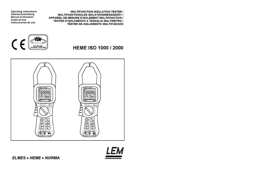
Liquid Instruments Moku:Pro User manual

liquidinstruments.com 2023 Liquid Instruments. All rights reserved.
V23-0128
Waveform Generator
Moku:Pro User Manual
The Moku:Pro Waveform Generator is designed to generate common signals with high accuracy
and configurability across four independent output channels. The outputs are precisely adjustable
for frequency, phase, and amplitude. Further, the outputs may be modulated with a variety of
internally generated or external signals and triggered from flexible, programmable triggers.

2| Moku:Pro Waveform Generator User Manual © 2023 Liquid Instruments. All rights reserved.
Table of contents
User interface....................................................................................................................................... 4
Main menu ............................................................................................................................................ 5
Preferences........................................................................................................................................... 6
Settings ................................................................................................................................................. 7
Output configuration........................................................................................................................... 8
Enable / disable outputs 8
Impedance 8
Waveform types 8
Sine wave 8
Square wave 10
Ramp wave 11
Pulse wave 12
Noise 12
DC wave 13
Modulation types 14
Amplitude modulation 14
Frequency modulation 15
Phase modulation 16
Pulse-width modulation 17
Triggered modulation modes 18
Instrument reference.........................................................................................................................20
Waveform types 20
Sine wave 20
Square wave 20
Ramp wave 20
Pulse wave 20
Noise 20
DC 20
Waveform parameters 20
Amplitude 20
Frequency 21
Offset 21
Phase 21
Symmetry 21
Pulse width 21
Edge time 21
DC level 21
Modulation types and trigger modes 22
Modulation sources 22
Trigger sources 22
Amplitude modulation 22
Frequency modulation 23
Phase modulation 23
Pulse-width modulation 23
Burst mode 23
Sweep mode 23

4| Moku:Pro Waveform Generator User Manual © 2023 Liquid Instruments. All rights reserved.
User interface
Moku:Pro is equipped with four output channels. You can tap the or icons to navigate
between channels.
ID
Description
ID
Description
1
Main menu
7
Configure output load (50 Ω or 1 MΩ)
2
Configure offset
8
Settings (Ch 2)
3
Configure modulation depth
9
Settings (Ch 3)
4 Enable / disable output 10 Configure square duty cycle
5
Waveform shape
11
Switch parameter representations
6
Configure modulation
12
Switch parameter representations

5| Moku:Pro Waveform Generator User Manual © 2023 Liquid Instruments. All rights reserved.
Main menu
The main menu can be accessed by pressing the icon, allowing you to:

6| Moku:Pro Waveform Generator User Manual © 2023 Liquid Instruments. All rights reserved.
Preferences
Access the preferences pane via the main menu. In here, you can reassign the color
representations for each channel, connect to Dropbox, etc. Throughout the manual, the default
colors (shown in the figure below) are used to present instrument features.
ID
Descrip
tion
1
Tap to change the color associated with input channels.
2
Tap to change the color associated with output channels.
3
Tap to change the color associated with math channel.
4
Indicate touch points on the screen with circles. This can be useful for demonstrations.
5
Change the currently linked Dropbox account to which data can be uploaded.
6
Notify when a new version of the app is available.
7
Moku:Pro automatically saves instrument settings when exiting the app, and restores them
again at launch. When disabled, all settings will be reset to defaults on launch.
8 Moku:Pro can remember the last used instrument and automatically reconnect to it at launch.
When disabled, you will need to manually connect every time.
9 Reset all instruments to their default state.
10
Save and apply settings.

7| Moku:Pro Waveform Generator User Manual © 2023 Liquid Instruments. All rights reserved.
Settings
Access the settings menu by tapping the icon. This gives you the option to instantly apply
settings from other channels to this channel. You can sync the output phase across all channels by
tapping sync phase.

8| Moku:Pro Waveform Generator User Manual © 2023 Liquid Instruments. All rights reserved.
Output configuration
Enable / disable outputs
shows the output channel is disabled, tap to enable.
shows the output channel is enabled, tap to disable.
Impedance
Moku:Pro analog outputs have an impedance of 50 Ω. As such, voltages supplied to a 50 Ω load
will be reduced by a factor of two due to the voltage divider formed by the closed circuit. Changing
the load impedance on the user interface does not affect the actual output voltage. Instead, it
scales the voltage displayed on the screen corresponding to the output load.
Waveform types
Each channel can be set to generate one of six predefined waveforms.
Sine wave

9| Moku:Pro Waveform Generator User Manual © 2023 Liquid Instruments. All rights reserved.
ID
Description
ID
Description
1
Amplitude (high level)
3
Offset (low level)
2
Signal Frequency (period)
4
Phase
Tap or click pill 1 - 4 to select and change values. The selected parameter is shown in, and can be
edited from, the bar below. Select alternative representations (shown in parentheses) by clicking
the button.

10 | Moku:Pro Waveform Generator User Manual © 2023 Liquid Instruments. All rights reserved.
Square wave
ID
Description
ID
Descriptio
n
1
Amplitude (high level)
4
Phase
2 Signal frequency (period) 5 Duty cycle
3
Offset (low level)
Tap or click pill 1 - 5 to select and change values. The selected parameter is shown in, and can be
edited from, the bar below. Alternative representations (shown in parentheses) can be selected by
clicking the button.

11 | Moku:Pro Waveform Generator User Manual © 2023 Liquid Instruments. All rights reserved.
Ramp wave
ID
Description
ID
Description
1
Amplitude (high level)
4
Phase
2 Signal frequency (period) 5 Symmetry
3
Offset (low level)
Tap or click pill 1 - 5 to select and change values. The selected parameter is shown in, and can be
edited from, the bar below. Alternative representations (shown in parentheses) can be selected by
clicking the button.

12 | Moku:Pro Waveform Generator User Manual © 2023 Liquid Instruments. All rights reserved.
Pulse wave
ID
Description
ID
Description
1
Amplitude (high level)
4
Phase
2 Signal frequency (period) 5 Pulse width
3
Offset (low level)
6
Edge time
Tap or click pill 1 - 6 to select and change values. The selected parameter is shown in, and can be
edited from, the bar below. Alternative representations (shown in parentheses) can be selected by
clicking the button.
Noise
ID
Description
ID
Description
1
Amplitude (high level)
2
Offset (low level)
Click pill 1, 2 to select and change values. The selected parameter is shown in, and can be edited
from, the bar below. Alternative representations (shown in parentheses) can be selected by
clicking the button.
1 2

13 | Moku:Pro Waveform Generator User Manual © 2023 Liquid Instruments. All rights reserved.
DC wave
ID
Description
1
DC level
Tap or click pill 1to select or change the DC value.

14 | Moku:Pro Waveform Generator User Manual © 2023 Liquid Instruments. All rights reserved.
Modulation types
The Moku:Pro Waveform Generator supports several modulation and triggering modes. The
modulation types available vary between waveforms: pulse-width modulation (PWM) only applies to
the Pulse waveform type, while Noise only supports Amplitude Modulation (AM) and reduced
triggering functionality. All other waveform types support amplitude, frequency, or phase
modulation as well as all available trigger options.
Amplitude modulation
ID
Parameter
Description
1
Frequency
Only for “Internal” modulation; the frequency of the sine wave being
used for modulation.
2
AM depth
Fractional depth of modulation. 100% depth will reduce the signal
amplitude to zero for a full-range negative modulation signal
3 Modulation source The modulation source can be an internally-generated sinewave,
Moku:Pro analog input, or another Waveform Generator channel.
When using an analog input, the user can further select the input
range, impedance, and coupling.

15 | Moku:Pro Waveform Generator User Manual © 2023 Liquid Instruments. All rights reserved.
Frequency modulation
ID
Parameter
Description
1
Frequency
Only for “Internal” modulation; the frequency of the sine wave being
used for modulation.
2
FM deviation
Full-range frequency deviation. A full-range input signal will vary the
output frequency by this amount.
3
Modulation source
The modulation source can be an internally-generated sinewave,
Moku:Pro analog input, or another Waveform Generator channel.
When using an analog input, the user can further select the input
range, impedance, and coupling.

16 | Moku:Pro Waveform Generator User Manual © 2023 Liquid Instruments. All rights reserved.
Phase modulation
ID
Parameter
Description
1
Frequency
Only for “Internal” modulation; the frequency of the sine wave being
used for modulation.
2
Depth
Full-range phase deviation. A full-range input signal will vary the
output phase by this amount.
3
Modulation source
The modulation source can be an internally-generated sinewave,
Moku:Pro analog input, or another Waveform Generator channel.
When using an analog input, the user can further select the input
range, impedance, and coupling.

17 | Moku:Pro Waveform Generator User Manual © 2023 Liquid Instruments. All rights reserved.
Pulse-width modulation
ID
Parameter
Description
1
Frequency
Only for “Internal” modulation source. The frequency of the sine wave
being used for modulation.
2
Depth
Full-range pulse-width deviation. A full-range input signal will vary the
output width by this amount.
3
Modulation source
The modulation source can be an internally-generated sinewave,
Moku:Pro analog input, or the other Waveform Generator channel.
When using an analog input, the user can further select the input
range, impedance, and coupling.
1 2
3

18 | Moku:Pro Waveform Generator User Manual © 2023 Liquid Instruments. All rights reserved.
Triggered modulation modes
Sine, square, ramp, pulse, and noise waves can be triggered from an internal or external source.
The behavior upon receipt of the trigger signal varies according to mode.
Burst
ID
Parameter
Description
1 Cycle count N Cycle and Gated mode only. The number of cycles or time to
output the waveform before re-arming.
2
Trigger source
One of:
Internal:
Trigger automatically at the defined rate.
External
: Trigger event on from rear-panel external trigger input.
Input
: Trigger from associated input channel, at given voltage.
Output
: Trigger from another output channel, at given voltage.
3
Mode
One of:
Gated
: Continue to generate the output signal while ever the trigger
event is asserted (level-triggered).
Start
: Begin generation of the waveform on trigger, continue
indefinitely.
N Cycle
: Upon receipt of trigger signal, generate N cycles of the
waveform then re-arm. Not supported for noise waveform.

19 | Moku:Pro Waveform Generator User Manual © 2023 Liquid Instruments. All rights reserved.
Sweep
Sweep modulation acts like frequency modulation with a sawtooth, where the sawtooth starts on
the trigger event.
Sweep modulation is not supported for the Noise waveform as it has no defined frequency.
ID
Parameter
Description
1 Start frequency Waveform frequency at the trigger event (sweep start).
2
End frequency
Waveform frequency at the sweep end.
3
Trigger source
One of:
Internal:
Trigger automatically at the defined rate.
External:
Trigger event on from rear-panel external trigger input.
Input:
Trigger from associated input channel, at given voltage.
Output:
Trigger from another output channel, at given voltage.
4
Sweep time
Time between sweep start and end (period).

20 | Moku:Pro Waveform Generator User Manual © 2023 Liquid Instruments. All rights reserved.
Instrument reference
Waveform types
The Moku:Pro Waveform Generator is capable of generating six different signals, each with
optional modulation.
Sine wave
The Sine wave is the simplest dynamic signal in the Moku:Pro. It features extremely low harmonic
distortion; it’s very close to a pure single frequency.
The Sine wave can be modulated by all available modulation types except PWM. Moreover, it forms
the basis of the “Internal” selectable modulation source, providing a modulating waveform
regardless of whether any channel of the Moku:Pro is currently outputting a Sine wave.
Square wave
The Square wave is a low-jitter waveform with fixed 50% duty cycle and high slew rates. The high
analog bandwidth of the Moku:Pro gives very sharp rise and fall times, highly desirable in many
applications. If you require slew-rate limits or variable duty cycle in your application, see Pulse
Wave below.
Ramp wave
The Ramp wave consists of linear ramps from low level to high and back again. The ratio between
the time spent rising and the overall period is referred to as the symmetry. If you require
configurable dwell times at the high or low levels but common rise and fall times, you may use the
Pulse wave with large edge times.
Pulse wave
The Pulse wave is like the Square wave but has configurable duty cycle and edge times (rise and
fall time). The trade-off is that at high frequency, Pulse has slightly worse edge jitter behavior
compared to the Square wave.
The Pulse wave also uniquely supports pulse-width modulation (PWM). When PWM is enabled,
edge times are fixed to their minimum values.
Noise
Approximately gaussian, white noise.
DC
Provides a high precision, fixed reference voltage at the output.
Waveform parameters
Amplitude
Applicable to: Sine, Square, Ramp, Pulse, Noise
Amplitude is specified as a Peak-to-Peak value; that is, the high level minus the low level. If you
wish to specify the high and low levels explicitly, tap the Amplitude pill then the toggle arrows in
Other manuals for Moku:Pro
2
Table of contents
Other Liquid Instruments Test Equipment manuals
Popular Test Equipment manuals by other brands
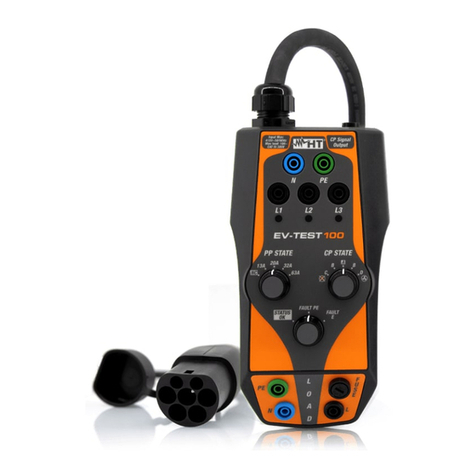
HT
HT EV-TEST100 user manual

yellow jacket
yellow jacket RecoverX-CAR Operation and maintenance manual
Everfine
Everfine LT- 101A user manual
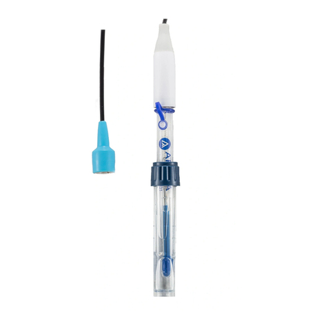
Apera Instruments
Apera Instruments LabSen 831 user manual
Viavi
Viavi Seeker X with MCA III installation guide
Vigor Equipment
Vigor Equipment V7548 operating instructions

