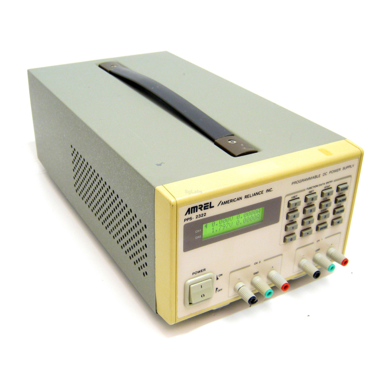
Amrel PQ Series User manual

OPERATION MANUAL
Revision 1.0
Release Date: 04/11/02
/AMERICAN RELIANCE, INC.
11801 GOLDRING ROAD, ARCADIA, CA 91006
PHONE: (626) 303-6688 FAX: (626) 358-3838
PQ Series
Programmable DC Power Supply

i
LIMITED WARRANTY
American Reliance warrants to the original user or purchaser that your unit is free from any defects
in material or workmanship for a period of one year from the date of purchase. If any defect is
discovered within the warranty period, American Reliance will repair or replace the unit, subject to
verification of the defect or malfunction, upon delivery or prepaid shipment to American Reliance.
IMPORTANT:
(1) Unless a problem is discovered upon initial inspection after purchase of the unit, please
do not return the product to the distributor where it was purchased. American Reliance accepts
the responsibility of keeping you a satisfied customer.
(2) If out-of-warranty or any service not covered by this warranty is needed, please contact
the American Reliance Service Department at (877) 267-4805 for current charges.
This warranty does not apply to defects or to physical damage resulting from abuse, neglect, accident,
improper repair, alteration, or unreasonable use of the unit, resulting in (but not limited to) cracked
or broken cases or parts, or to units damaged by excessive heat. Except upon initial purchase, this
warranty does not cover finish or appearance items nor does it cover items damaged in shipment to
American Reliance for repair or calibration.
To receive service under this warranty, you must include proof of purchase, including date and place
of purchase (a copy of your purchase receipt) or we will not be responsible for repairs or replacement
of the unit under warranty.
American Reliance assumes no responsibility for shipping and handling. However, repaired units will
be shipped back to the customer with return shipping charges paid by American Reliance.
Any applicable implied warranties, including warranties of merchantability and fitness for a
particular use, are hereby limited to three years from the date of purchase. Consequential or
incidental damages resulting from loss of use, or from a breach of any applicable express or implied
warranties are hereby excluded.
This warranty is in lieu of all other agreements and warranties, general or specific, express or
implied. No representative or person is authorized to assume for us any other liability in connection
with the sale or use of this American Reliance product.
Some states do not allow limitations on how long implied warranties last and do not allow exclusion
of incidental or consequential damages, so the above limitations and exclusions may not apply to
you. This warranty gives you specific legal rights that may vary from state to state.

ii
NON-WARRANTY SERVICE
Any American Reliance out-of-warranty instrument that is thought to be defective, but is repairable,
may be sent in for non-warranty service. Please contact our service department at (626) 303-6688
for current repair charges.
The instrument should be returned to American Reliance, please follow the directions under the
heading "Shipping Instructions" in this section.
SHIPPING INSTRUCTIONS
Any product returned to American Reliance for service must be shipped, freight prepaid (we will
not accept COD shipments).
American Reliance Inc.
5440 Peck Rd.,
El Monte, CA 91732
Attn: RMA # _________________
Please obtain return authorization from AMREL before returning any product.
The instrument must be carefully packed, preferably in its original carton with PE Foam, and
should be accompanied by a letter or note containing the following information:
User's Name Proof of Purchase
User's Address Description of problem
Model number Serial number
If service is desired, such as calibration, it must be stated in the enclosed letter. For non-warranty
repairs, and for calibration, the correct service charge must accompany the unit in the form of a
check or money order payable to American Reliance Inc. Please do not send cash. Contact our
service department at (877) 267-4805.
American Reliance will return the serviced instrument, with freight paid by American Reliance,
via UPS ground service unless otherwise requested.
NOTE: ALL INSTRUMENTS THAT ARE RETURNED FOR REPAIR OR
CALIBRATION MUST HAVE AN ASSIGNED R.M.A. NUMBER WRITTEN ON THE
FRONT OF THE PACKAGE. THIS NUMBER MAY BE OBTAINED BY OUR SERVICE
DEPARTMENT. ANY INSTRUMENT DELIVERED WITHOUT THIS NUMBER WILL BE
REFUSED, AND RETURNED.

iii
TABLE OF CONTENTS
Section Title Page
1.0 GENERAL INFORMATION 1
1.1 Description 1
1.2 Features 1
1.3 Cooling 2
1.4 Installation 2
1.5 Power Requirements 2
1.6 Specifications 2
2.0 OPERATING INSTRUCTIONS 7
2.1 General Operation 7
2.2 Controls and Indicators 7
2.3 Preparation for Use 7
2.3.1 Unpacking 7
2.3.2 Electrical Check 8
2.4 Modes of Operation 9
2.4.1 Normal Mode 9
2.4.2 Constant Voltage 9
2.4.3 Constant Current 10
2.5 Remote Sensing 10
2.6 Standard Programming 10
2.7 Remote Programming 13
2.7.1 Resistive Programming 13
2.7.2 Voltage Programming 15
2.7.3 Current Programming 15
2.8 Voltage and Current Monitoring 16
2.9 Digital Control Lines 16
2.10 Diagnostic Functions 19
2.11 Parallel Operation 20
2.11.1 Parallel Operation - Direct 20
2.11.2 Parallel Operation - Master/Slave 20
2.12 Series Operation 21
2.12.1 Series Operation - Direct 21
2.12.2 Series Operation - Master/Slave 21
2.13 Pulse Loading 23
2.14 Conversion to 240/440 V Operation 23
2.15 Nomenclature 23

iv
3.0 PRINCIPLES OF OPERATION 27
3.1 General 27
3.2 Theory of Operation 29
3.2.1 Power Circuit 29
3.2.2 Input Board 30
3.2.3 Chopper Module 30
3.2.4 Inverter Module 30
3.2.5 Output Module 31
3.2.6 Other Printed Circuit Boards 31
4.0 MAINTENANCE AND TROUBLE SHOOTING 32
4.1 General 32
4.2 Trouble Shooting Guide 32
4.3 Calibration 33
4.3.1 Control Board 33
4.3.2 Driver Board 34

1
1.0 GENERAL INFORMATION
1.1 Description
This manual contains operation and maintenance instructions for American Reliance's PQ Series,
medium frequency link power supplies. These power supplies are constant voltage/constant current
sources suitable for a wide range of applications.
1.2 Features
American Reliance’s PQ SERIES power supplies set a new standard for high-powered dc supplies.
A combination of high and medium frequency power processing technologies improves response,
shrinks package size, and reduces cost. PQ SERIES power supplies are current fed. Compared with
conventional switching power supplies, these supplies can easily tolerate the punishment of the most
rigorous applications.
PQ SERIES power supplies are fully programmable via resistance, voltage, current, or optional
IEEE-488/RS232. While other supplies can remotely control only output voltage and current, PQ
SERIES units also allow programming of over voltage and over current protection. Program lines
are constantly monitored for range of operation. If a line should open or if a programmable input is
set beyond that anticipated, the unit safely shuts down protecting the load.
PQ SERIES power supplies can operate as a voltage source or current source depending on the
control settings and load conditions. If the power supply is operating as a voltage source and the load
increases to a point beyond the current command setting, the power supply automatically crosses
over to current mode control and operates as a current source at that setting.
Differential amplifiers isolate the programming lines from the dc output allowing programming at
any distance from the load. Additional differential amplifiers are provided for master/slave series
or parallel operation.
Diagnostic functions are contained directly within the supply’s control loop. Exclusive circuitry
eliminates guesswork about which function has control -- voltage, current, or a fault condition. If
the fault condition requires user attention, main power is disconnected and the diagnostic condition
is latched into memory. Pressing the reset switch clears the memory. All diagnostic functions are
monitored with optical isolators that can be paralleled for master/slave operation. Furthermore,
control functions can also be set through optical isolators to allow simultaneous control of one or
more PQ SERIES units. Programming switches in the rear of the supply enable internal operation
of controls, external operation, or both.
PQ SERIES supplies have three levels of over voltage/current protection: shutdown of controlling
insulated gate bipolar transistors (IGBT’s), disconnect of main power, and optional SCR crowbar.
After an over voltage/current condition, the supply must be reset. Pressing the reset switch causes
the over voltage/current settings to be displayed on the front meters.

2
PQ SERIES power supplies have push button start/stop controls. These controls are electrically
integrated to a mechanical contactor which operates with the electronic switches to break the ac
mains when stop is commanded. Unlike competing products, an off means both an electrical and
mechanical break in the power circuit — not a break in an electronic switch. Safety comes first at
American Reliance.
1.3 Cooling
Each power supply enclosure is cooled by suitable blowers exhausting warm air to the rear of the
cabinet. Fresh air intake is from the sides of the cabinet allowing two or more PQ Series supplies
to be stacked. Blocking ventilation will cause the power supply to overheat.
1.4 Installation
The power supply is capable of being rack or bench mounted. For rack mount installations, additional
support, other than that provided by the front panel, is required. Angle slides or cross beam supports
securely fastened to the rack are recommended for supporting the weight of the power supply. The
unit should be horizontally mounted.
1.5 Power Requirements
A suitable source of ac power is required for this supply. The unit is wired for 208 V, 3N, 50 to 60
Hz mains. For 240 V operation, two internal wiring changes must be made to the unit. Information
concerning conversion is covered in Section 2.14.
PQ Series power supplies are optionally available for operation on 440/480 V, 3N, 50 to 60 Hz
mains. Units are normally wired for 480 V operation and information concerning conversion is
covered in Section 2.14.
1.6 Specifications
The following specifications describe the published operational characteristics of the PQ series power
supplies.
Input voltage: 208/240 Vac, 50-60 Hz, 3Nstandard; 440/480 Vac, 50-60 Hz, 3Noptional.
Regulation line and load combined: 0.10 %.
Stability: 0.10 % for 8 hours after 30 minute warm up.
Transient response: 40.0 ms to recover within 2 % of regulated output with a 30 % step load change.

3
Programming resistors: 1 KSfull scale for output voltage, output current, over voltage shutdown,
and over current shutdown.
Ambient Temperature: 0 to 50°C.
Storage Temperature: -25 to +85°C.
Temperature coefficient: 0.04 %/°C of maximum output current.
Size: 5¼"H x 19"W x 24"D, see figure 1.1 for details.
Weight: 125 lbs for 10 kW models, 97 lbs for 6.6 kW models, and 74 lbs for 3.3 kW models.
10 KW MODELS AND RATINGS
MODEL
VOLTS
Vdc
AMPS
Adc
RIPPLE
mVrms
EFF.
%
INPUT CURRENT (Aac)
208/240 V
MODELS
440/480 V
MODELS
PQ16-600
PQ20-500
PQ32-300
PQ40-250
PQ50-200
PQ80-125
PQ100-100
PQ125-80
PQ160-62
PQ200-50
PQ250-40
PQ375-27
PQ500-20
PQ625-16
16
20
32
40
50
80
100
125
160
200
250
375
500
625
600
500
300
250
200
125
100
80
62
50
40
27
20
16
40
35
30
35
40
50
55
60
70
80
90
100
130
150
86
86
86
87
87
87
87
87
87
87
88
88
88
88
36
36
36
36
36
36
35
35
35
35
35
35
35
35
18
18
18
18
18
18
17
17
17
17
17
17
17
17

4
6.6 KW MODELS AND RATINGS
MODEL
VOLTS
Vdc
AMPS
Adc
RIPPLE
mVrms
EFF.
%
INPUT CURRENT (Aac)
208/240 V
MODELS
440/480 V
MODELS
PQ10-600
PQ16-400
PQ20-330
PQ32-200
PQ40-165
PQ50-130
PQ80-82
PQ100-66
PQ125-53
PQ160-41
PQ200-33
PQ250-26
PQ375-17
PQ500-13
PQ625-10
10
16
20
32
40
50
80
100
125
160
200
250
375
500
625
600
400
330
200
165
130
82
66
53
41
33
26
17
13
10
40
40
35
30
35
40
50
55
60
70
80
90
100
130
150
86
86
86
86
87
87
87
87
87
87
87
88
88
88
88
24
24
24
24
24
24
24
23
23
23
23
23
23
23
23
12
12
12
12
12
12
12
12
12
12
12
12
12
12
12

5
3.3 KW MODELS AND RATINGS
MODEL
VOLTS
Vdc
AMPS
Adc
RIPPLE
mVrms
EFF.
%
INPUT CURRENT (Aac)
208/240 V
MODELS
440/480 V
MODELS
PQ10-300
PQ16-200
PQ20-165
PQ32-100
PQ40-82
PQ50-65
PQ80-41
PQ100-33
PQ125-26
PQ160-20
PQ200-16
PQ250-13
PQ375-8
PQ500-6
PQ625-5
10
16
20
32
40
50
80
100
125
160
200
250
375
500
625
300
200
165
100
82
65
41
33
26
20
16
13
8
6
5
40
40
35
30
35
40
50
55
60
70
80
90
100
130
150
86
86
86
86
87
87
87
87
87
87
87
88
88
88
88
12
12
12
12
12
12
12
12
12
12
12
12
12
12
12
6
6
6
6
6
6
6
6
6
6
6
6
6
6
6
Notes:
1) Rating specified at 208 and 440 V input.
2) Specifications subject to change without notice.

6
Figure 1.1 PQ Series package drawing

7
2.0 OPERATING INSTRUCTIONS
2.1 General Operation
As shipped, the power supply is configured for local sensing, internal programming, and 208 V, 3N
input. The front panel voltage and current controls set the boundary limits for output voltage and
current, respectively. The impedance of the load determines whether the unit is voltage or current
controlled and the illumination of the respective mode indicator light indicates the state. If either
control is set to maximum counter clockwise rotation, the other control will have little or no effect.
Each control must be set to the appropriate position for proper operation.
2.2 Controls and Indicators
The controls and indicators are illustrated in figure 2.1.
Figure 2.1 Controls and indicators
2.3 Preparation for Use
2.3.1 Unpacking
Carefully unpack the power supply saving all packing materials and included enclosures. Inspect
power supply for possible shipping damage. Check that there are no broken knobs or connectors,
the external surface is not scratched or dented, the meter faces are not damaged, and all controls
move freely. Any external damage may be an indication of internal damage.

8
2.3.2 Electrical Check
Check that switches S1 and S2, located at the rear of the supply, are set to position 1, the default
switch positions. As shown in figure 2.2, switch positions depict normal local sense and
programming configurations. It is recommended that the following brief electrical check be made
shortly after unpacking the supply.
Figure 2.2 Default switch positions for S1 and S2 (on is state 1 and off is state 0)
Set voltage and current controls full counterclockwise, turn the power switch off and connect a short
circuit to the power output studs on the rear panel. Connect the power supply to a suitable source
of ac voltage. For this test, only 50% of rated ac current is required.
Turn the power switch on. The standby, internal control (int ctl), and external control (ext ctl) lights
should come on. Press the start switch and advance the voltage control one turn clockwise. The
standby light should extinguish and the power and current control lights should come on. Press the
display/reset switch and adjust the over current trip to maximum current by means of the screw
driver adjustment potentiometer. Increase the current setting to maximum and then to minimum.
DC current should increase smoothly from minimum to maximum to minimum as indicated on the
meter. Return the current control full counterclockwise.
Press the display/reset switch and adjust the over current trip to half-rated current. Slowly increase
the current setting. Over current trip should operate at the over current trip setting, the over current
light should come on, and the supply should shut down. Press the display/reset switch and adjust the
over current trip to maximum current. Adjust the current control full counterclockwise and restart
the supply. The supply should operate normally

9
With the power supply off, disconnect the output short circuit. Turn the power switch on. Press the
start switch and advance the current control one turn clockwise. The standby light should extinguish
and the power and voltage control lights should come on. Press the display/reset switch and adjust
the over voltage trip to maximum voltage by means of the screw driver adjustment potentiometer.
Increase the voltage setting to maximum and then to minimum. DC voltage should increase
smoothly from minimum to maximum to minimum as indicated on the meter. Return the voltage
control full counterclockwise.
Press the display/reset switch and adjust the over voltage trip to half-rated voltage. Slowly increase
the voltage setting. Over voltage trip should operate at the over voltage trip setting, the over voltage
light should come on, and the supply should shut down. Press the display/reset switch and adjust
the over voltage trip to maximum voltage. Adjust the voltage control full counterclockwise and
restart the supply. The supply should operate normally.
If any of these events do not occur, the supply is defective and should not be operated. Depending
on the circumstances, either warranty service or trouble shooting as described in Section 4.2 is
required.
2.4 Modes of Operation
2.4.1 Normal Mode
PQ series power supplies are normally shipped with its switch settings arranged for constant
voltage/constant current, local sensing, and local programming. This is set by the programming
switches, S1 and S2, located at the rear of the supply. As illustrated in figure 2.2, all of the
programming switches should be set to position 1. The operator selects either a constant voltage or
a constant current output using the front panel controls (local programming, no switch changes are
necessary).
2.4.2 Constant Voltage
To select a constant voltage output, proceed as follows:
With the supply off, set all controls to full counterclockwise and advance current control one turn
clockwise. Turn on the power supply and adjust the voltage trip to 110% of desired output
voltage. Advance the voltage control for the desired output voltage with the output terminals
open.
Turn the supply off and short the output terminals. Turn on the supply and adjust the current
control for the maximum output current allowable as determined by load conditions. If a load
change causes the current limit to be exceeded, the power supply will automatically crossover to
constant current output at the preset current limit and the output voltage will drop proportionately.
In setting the current limit, allowance must be made for high peak currents which can cause
unwanted crossover (see section 2.13).

10
Turn off the power supply, remove the short on the output terminals, and connect the load. The
unit is now ready for operation.
2.4.3 Constant Current
To select a constant current output, proceed as follows:
With the supply off, short the output terminals, set all controls to full counterclockwise, and
advance the voltage control one turn clockwise. Turn on the power supply and adjust the current
trip to 110% of desired output current. Advance the current control for the desired output current
with the output terminals shorted.
Turn off the supply and remove the short on the output terminals. Turn on the power supply and
adjust the voltage control for maximum output voltage allowable as determined by load
conditions. If a load change causes the voltage limit to be exceeded, the power supply will
automatically crossover to constant voltage output at the preset voltage limit and the output
current will drop proportionately.
Turn off the power supply and connect the load. The unit is now ready for operation.
2.5 Remote Sensing
Remote sensing is used to improve the degradation of regulation which will occur at the load
when the voltage drop in the connecting wires is appreciable. This is done by setting switch
positions 1 and 2 of S1 to 0. Using a pair of #20 AWG wires, connect terminal 2 of JS2 to the
positive terminal of the load and connect terminal 1 of JS2 to the negative terminal of the load.
Figure 2.3 illustrates standard output sensing and remote output sensing.
2.6 Standard Programming
The standard programming configuration, illustrated in figure 2.4, shows that references for
voltage, current, voltage trip, and current trip are established by internal 2 mA current sources
producing voltages across potentiometers RV, RI, RTV, and RTI. These potentiometers are the
front panel controls for voltage, current, voltage trip, and current trip, respectively.
Resistors placed in series with the voltage and current trip potentiometers allow settings above
the maximum voltage and current of the power supply.

11
Figure 2.3 (a) Standard and (b) remote sensing

12
Figure 2.4 Standard programming configuration using internal potentiometers

13
2.7 Remote Programming
PQ series supplies allow voltage, current, voltage trip, and current trip to be programmed from a
remote location. Programming can be accomplished either by resistive, voltage, or current
programming circuits.
Figure 2.5 illustrates the three alternatives for programming output voltage. The method applies
equally to programming an output current, voltage trip, and current trip.
2.7.1 Resistive Programming
Resistive programming requires setting position 2 of S2 to 0 and connection of an external
potentiometer or resistor between terminals 20 and 4 of JO2. Like the internal voltage
potentiometer, the 2 mA reference produces a voltage across the potentiometer or resistor which
is used to set the output voltage. A metal film resistor or wire wound potentiometer will result in
the lowest temperature coefficient.
To program an output current, voltage trip, or current trip, use the same method and refer to
figure 2.4 for terminal identification.
The expressions for programming output voltage, VO, output current, IO, voltage trip, TV, and
current trip, TIare given as follows.
(1)
(2)
(3)
(4)
where:
VOMAX: maximum output voltage,
IOMAX : maximum output current,
RP: programming resistor.

14
Figure 2.5 External (a) resistive, (b) voltage, and (c) current programming

15
2.7.2 Voltage Programming
Voltage programming requires setting positions 1 and 2 of S2 to 0 and connection of an external
voltage reference between terminal 7 of JO2 (positive) and terminal 4 of JO2 (negative).
To program an output current, voltage trip, or current trip, use the same method and refer to figure
2.4 for terminal identification.
The expressions for programming output voltage, VO, output current, IO, voltage trip, TV, and current
trip, TI, are given as follows.
(5)
(6)
(7)
(8)
where:
VP: programming reference voltage.
2.7.3 Current Programming
Current programming requires setting positions 1 and 2 of S2 to 0, connection of an external, 1K
metal film resistor between terminal 7 of JO2 and terminal 4 of JO2, and connection of an external
current source between terminal 7 of JO2 (positive) and terminal 4 of JO2 (negative).
To program an output current, voltage trip, or current trip, use the same method and refer to figure
2.4 for terminal identification.
The expressions for programming output voltage, VO, output current, IO, voltage trip, TV, and current
trip, TI, are given as follows.
Table of contents
Other Amrel Power Supply manuals