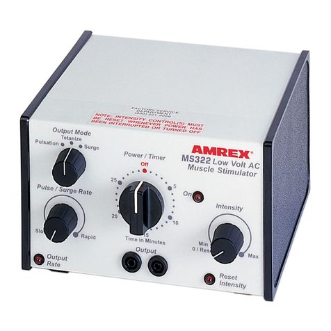
Amrex MS401B User manual

*Federal law (USA) restricts this device to sale by or on the order of a licensed practitioner licensed by the law of the state in which he
practices to use or order the use of this device.
User's Guide
MS401B*
Muscle Stimulator
Amrex
®
electrotherapy equipment
a division of Amrex-Zetron, Inc.

AMREX®electrotherapy equipment
a division of Amrex-Zetron, Inc.
7034 Jackson Street
Paramount, California 90723
(310) 527-6868
Toll Free Customer Service (800) 221-9069
Fax (310) 366-7343
E-Mail: [email protected]
Web Site: http://www.amrexusa.com
MS401B User's Guide
Stimulator
Revised February 2014
Copyright © Amrex-Zetron, Inc. 1995. All rights reserved.
Printed in the United States of America
The following are registered or trademarked by Amrex:
Amrex®
Flextrode®

i
Thank you. . .
for selecting the Amrex MS401B Stimulator. We believe that you will find this
instrumenttobe versatile,dependable, anduser friendly.The MS401Bis designed
fortheapplicationofmusclestimulation.TheAmrexMS401B Stimulatorisa four-
channel, eight-pad, electrical muscle stimulator that produces bi-phasic, mono-
phasic, surge and reciprocal output.
Your MS401B has been manufactured by a group of dedicated, highly trained
employees who exemplify the Amrex tradition, since 1935, of manufacturing
therapeutic equipment of the highest quality while supporting you with prompt,
courteous customer service.
Upon receipt of your MS401B, verify your accessories against the enclosed check
list. Promptly return the postage paid Registration Card to Amrex or register on-
lineatamrex-zetron.com.Savetheoriginalshippingcartonandallpackingmaterials.
Please carefully review this User’s Guide prior to operating the Amrex MS401B
Stimulator. Shouldyouhaveanyquestionsregardingyour new purchase,orneed
assistance, telephoneAmrex Technical Services at (800) 221-9069.

ii
Limited Warranty
Amrex-Zetron, Inc. (Manufacturer) warrants each instrument it manufactures to be free from
defects in material and workmanship under normal use and service for a period of two (2) years
fromthedateofpurchase. Thistwoyearwarrantyextendsonlytotheoriginalpurchaserandshall
not apply to batteries, fuses, accessories or any instrument which has been subjected to misuse,
neglect,accident orabnormal conditions of operation.
The Manufacturer's obligation under this warranty is limited to repairing or replacing, at the
Manufacturer's option, any instrument returned to the factory within two (2) years from the date
ofpurchase. IftheManufacturerdeterminesthattheproductfailstoconformtothiswarrantydue
to misuse, alteration or abnormal condition of operation, including evidence that nonauthorized
personnel have attempted to repair the device, the instrument will be repaired at customers
expense. This warranty is exclusive and in lieu of all other warranties, expressed or implied,
including but not limited to any other warranty of merchantability or fitness for any particular
purpose. Manufacturer shall not be liable for any special, incidental or consequential damages,
whether in contract, tort or otherwise.
Service and Shipping Information
AmrexTechnicalServiceshasarepresentativetoassistyoushouldyourequipmentrequireservice
or repair. It is necessary to obtain a Return Merchandise Authorization (RMA) number before
returning equipment to the factory for warranty repair. Call our representative toll free (800) 221-
9069.Damage, resultingfromrepairs made outsidethe factory, isnot coveredunderthe warranty.
To maintain original design specifications, your Amrex muscle stimulator must be calibrated and
safety tested on an annual basis. Amrex strongly recommends that servicing be referred to the
factory. Call toll free (800) 221-9069.
Save the original shipping carton and all packing materials to safely returnAmrex equipment to
the factory for service; repair; annual calibration, electrical and mechanical safety check. All
accessories,includingtheaclinecord,mustbeincludedwith thereturnedinstrument.The customer
isresponsibleforallfreightcharges.TheManufacturer shallassumeNOresponsibilityfor damage
intransit.

iii
Contraindications—Warnings—Precautions
THIS INSTRUMENT OPERATES ON 120 VOLTS AC, 60 Hz. (unless otherwise indicated on the
unit) AND MUST BE PROPERLY GROUNDED FOR SAFETY. The three wire power cord with
"hospitalgrade" plug shouldbe connected toa GROUNDEDAC wall receptacle.It is thepersonal
responsibility and obligation of the user to insure that this instrument is properly connected to
the AC POWER source before use.
Warning–Risk of burns and fire. DO NOT use near conductive
material such as metal bed parts or innerspring mattresses. Renew
electrode cables upon evidence of deterioration. Use of controls,
adjustment,orperformanceof procedures,otherthanthose specified
herein, may result in hazardous exposure to electrical energy.
Important
AMREX Intensity Reset Circuit: The Amrex MS401B Stimulator incorporates a unique safety
reset function as part of the intensity controls. This is to prevent any sudden or inadvertent
stimulation output to the patient in the event that:
•The MS401B Intensity controls are not set to the 0/Reset position enabling the audible
"clicks" at power on, provided the power has been off for more than ten seconds.
•The ac power is interrupted for more than ten seconds before power is restored.
•The treatment period has ended and more than ten seconds has elapsed before power on.
TheIntensity controls must be returnedto the 0/Reset position enablingthe audible"clicks" before
stimulation output can be activated.
Patient"TreatmentStop"Switch: Whenthepatient"TreatmentStop"switchisactivated, stimulator
output will be discontinued immediately. The Reset Intensities indicator light will illuminate.
Stimulator output cannot be resumed until the MS401B Intensity controls for ChannelA, Channel
B, Channel C, and Channel D are returned to the 0/Reset position enabling the audible "clicks"
which will turn off the Reset Intensities indicator light. NOW the Ready indicator light will
illuminate and stimulator output can beactivated

iv
ElectricalMuscleStimulation—Contraindications
•Contraindicatedforpatients with cardiacdemandpacemakers.
•Should not be used on cancer patients.
ElectricalMuscleStimulation—Warnings
•Long term effects of chronic electrical stimulation are unknown.
•Safetyhasnotbeenestablishedfortheuseofelectricalmusclestimulationduring pregnancy.
•Adequateprecautionsshouldbetakeninthecaseofpersonswithsuspectedheart problems.
•Adequate precautions should be taken in the case of persons with suspected or diagnosed
epilepsy.
•Donotstimulateoverthecarotidsinusnerves,especiallyinpatientswithaknownsensitivity
to the carotid sinus reflex.
•Severespasmofthelaryngealand pharyngeal muscles may occur when the electrodes are
positioned over the neck or mouth. The contractions may be strong enough to close the
airwayor cause difficultyin breathing.
•Electrical muscle stimulators should not be applied transcerebrally.
•Electrical muscle stimulators should not be used over swollen, infected or inflamed areas
or skin eruptions.
•Caution should be used in the transthoracic application of electrical muscle stimulators in
that the introduction of electrical current into the heart may cause arrhythmias.
•Electrical muscle stimulators should be kept out of the reach of children.
ElectricalMuscleStimulation—Precautions
Precautions should be observed:
•When there is a tendency to hemorrhage following acute trauma or fracture.
•Following recent surgical procedures when muscle contraction may disrupt the healing
process.
•Over the menstruating uterus.
•Where sensory nerve damage is present by a loss of normal skin sensation.
Some patients may experience skin irritation or hypersensitivity due to the electrical
stimulation or the conductive medium. The irritation can usually be reduced by use of an
alternate conductive medium or alternate electrode placement.
Skinirritationandburns beneaththeelectrodeshavebeenreported withtheuseof electrical
muscle stimulators.

v
Table of Contents
Part 1
Overview ................................................................................................................................ 1
Part 2
Power Section ........................................................................................................................ 5
Part 3
MS401B Stimulator Modality............................................................................................. 9
Part 4
MS401B General Operation and Application Procedures ............................................ 17
GeneralOperation....................................................................................................................... 17
ApplicationofElectricalMuscleStimulation .......................................................................... 19
Adverse Effects - Shortwave Diathermy Interference ........................................................... 20
ElectricalMuscleStimulation—Indications ............................................................................. 21
ElectricalMuscleStimulation—Contraindications ................................................................. 21
ElectricalMuscleStimulation—Warnings................................................................................ 21
ElectricalMuscleStimulation—Precautions............................................................................ 22
Appendix A
Specifications....................................................................................................................... 23
Appendix B
References ............................................................................................................................. 25

vi

The layout of the MS401B panel consists of controls, indicator lights, and output
jacks.
MS401B User's Guide 1
Overview
Part 1
AMREX
S u r g e R e c i p
C o n t i n u o u s
H o l d
B i
P h a s i c
M o n o
P h a s i c

2MS401B User's Guide
Part 1
In the illustration below, dashed lines surround each of the MS401B's sections.
A brief description of each section follows the illustration, and Parts 2 and 3
of this manual contain detailed descriptions.
S u r g e R e c i p
C o n t i n u o u s
H o l d
B i
P h a s i c
M o n o
P h a s i c

MS401B User's Guide 3
Overview
PowerSection
UsethePower/Timertoactivate the mainacpower andset thetreatment duration.
The power will shut off and a bell will sound when the treatment is complete.
MS401B Stimulator Modality Section
Set the intensities and monitor the output of stimulation with the controls and
connectors in this section of the panel. Select either mono phasic, bi phasic,
continuous, surge or reciprocal output using the Waveform and Output Mode
controls. Regulate the frequency of the pulses using the Pulse Rate control. Adjust
the duration of the surge or reciprocal output, with the Surge On/Recip A and B
On and Surge Off/Recip C and D On controls.

4MS401B User's Guide
Part 1

Power Section
MS401B User's Guide 5
In the illustration below, dashed lines surround the MS401B's power section.
Part 2
AMREX
S u r g e R e c i p
C o n t i n u o u s
H o l d
B i
P h a s i c
M o n o
P h a s i c

6MS401B User's Guide
Part 2
The power section of the MS401B front panel and rear panel is depicted below.
Items referenced with circled numbers (1 – 3) are explained on the following page.
Surge Recip
Continuous
Hold
Bi
Phasic
Mono
Phasic
M a n u f a c t u r e d b y :
A M R E X
e l e c t r o t h e r a p y e q u i p m e n t
a d i v i s i o n o f A m r e - Z e t r o n , I n c .
6 4 1 E a s t W a l n u t S t r e e t , C a r s o n , C A 9 0 7 4 6
C A U T I O N : F e d e r a l L a w R e s t r i c t s T h i s D e v i c e T o
S a l e B y O r O n T h e O r d e r O f A P h y s i c i a n O r O t h e r
P r a c t i t i o n e r L i c e n s e d B y T h e L a w .
M a d e i n U . S . A .
M A N U F A C T U R E D : M a y 2 0 0 6
M O D E L : S E R IA L N O .
M S 4 0 1 B X X X X X

MS401B User's Guide 7
Power Section
1. POWER/TIMER: Controlsthemain acpower aswell asthe timerfor treatment.
Turnthe Power/Timerknobclockwisepastthe10minutemarkandthenset it to
the desired treatment time. The On indicator light (located above the upper
right corner of the Power/Timer) will illuminate. The ac power will shut off
and a bell will sound when treatment is completed. To initiate early shut off,
turn the Power/Timer knob counterclockwise to the Off position. The ac power
will shut off and a bell will sound.
2. AC RECEPTACLE: Connection for MS401B's ac power cord.
3. VELCRO WASHER: To attach wall mount velcro bracket strap.

8MS401B User's Guide
Part 2

MS401B User's Guide 9
In the illustration below, dashed lines surround the MS401B's stimulator section.
MS401B Stimulator Modality
Part 3
AMREX
S u r g e R e c i p
C o n t i n u o u s
H o l d
B i
P h a s i c
M o n o
P h a s i c

10 MS401B User's Guide
Part 3
The stimulator section of the MS401B panel is depicted below. Items referenced
with circled numbers (4 – 8) are explained on the following page.
S u r g e R e c i p
C o n t i n u o u s
H o l d
B i
P h a s i c
M o n o
P h a s i c

MS401B User's Guide 11
MS401B Stimulator Modality
4. OUTPUT MODECONTROL:(SELECTIONS):
•Surge – Provides surged output simultaneously on Channel A, B,
C, and D. ( for Channel A, B, C, and D in Surge mode, the output
onrate is selectablefrom 1.0,2.5, 5.0, 7.5,10,15, 20, or30 seconds,
and the output off rate is selectable from 2.5, 5.0, 10, 15, 20, 30,
50, or 90 seconds ).
•Continuous–ProvidescontinuousoutputforChannelA,B, C, andD.
•Recip–Provides reciprocal output thatalternates between Channel
A &B and Channel C &D ( for Channel A &B output on, the
reciprocal rate is selectable from 1.0, 2.5, 5.0, 7.5, 10, 15, 20, or 30
seconds, and for Channel C &D output on, the reciprocal rate is
selectable from 2.5, 5.0, 10, 15, 20, 30, 50, or 90 seconds ).
5. WAVEFORMCONTROL:(SELECTIONS):
•Mono Phasic – Output pulses are of one polarity only.
•Hold – When selected during treatment, stimulator output is
discontinuedimmediately. This selectionis useful, during multi-
channel treatments when one set of pads must be readjusted, as
an alternative to turning the unit off and going through the reset
procedure.(When switchedback to the Mono Phasicor BiPhasic
waveform, the output intensities return to the previous settings
after a five second delay)
•Bi Phasic – Output pulses of two polarities, i.e. every positive pulse
is followed by a negative pulse.
6. PULSE RATE CONTROL: Select the pulse rate for Channel A, B, C, and D.
• Pulse rate selections are 1, 3, 5, 10, 20, 28, 40, 60, 80, 100, 120, and
160 pulses per second.
7. SURGE - ON / RECIP - A AND B ON CONTROL: Select the Surge mode 'on'
rate for Channel A, B, C, and D or the Recip mode 'on' rate for Channel A and B.
•Surge mode – The Surge - On rate selections for Channel A, B, C, and
Doutput are 1.0, 2.5, 5.0, 7.5, 10, 15, 20, or 30 seconds.
•Recip mode – The Recip - A and B On rate selections for Channel A
and Boutput are 1.0, 2.5, 5.0, 7.5, 10, 15, 20, or 30 seconds.
8. SURGE - OFF / RECIP - C AND D ON CONTROL: Select theSurge mode 'off'
rate for Channel A, B, C, and D or the Recip mode 'on' rate for Channel C and D.
•Surge mode – The Surge - Off rate selections for Channel A, B, C, and
Doutput are 2.5, 5.0, 10, 15, 20, 30, 50, or 90 seconds.
•Recip mode – The Recip - C and D On rate selections for Channel C
and Doutput are 2.5, 5.0, 10, 15, 20, 30, 50, or 90 seconds.

12 MS401B User's Guide
Part 3
The stimulator section of the MS401B panel is depicted below. Items referenced
with circled numbers (9 – 16) are explained on the following page.
S u r g e R e c i p
C o n t i n u o u s
H o l d
B i
P h a s i c
M o n o
P h a s i c
Table of contents
Other Amrex Fitness Equipment manuals