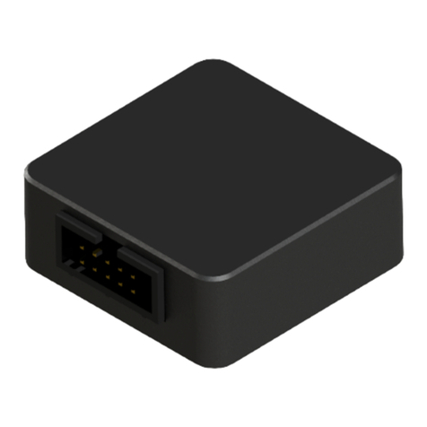
AMS AFDAU T-1 User manual

AMS-IM-1-01 Rev. 7
22 September 2021
AFDAU T-1
Aerial Firefighting Data Acquisition Unit
Installation Manual

AFDAU-T1 Aerial Firefighting
Data Acquisition Unit
Installation Manual
AMS-IM-1-01 Rev. 7
22 September 2021
i
Copyright Statement
© 2020 Airborne Mission Systems Pty Ltd. (AMS), All rights Reserved
This publication is the property of Airborne Mission Systems Pty Ltd (AMS) and is protected by Australian copyright
laws. No part of this document may be reproduced or transmitted in any form or by any means including electronic,
mechanical, photocopying, recording, or otherwise, without the prior written permission of AMS.
Product Warranty
This product manufactured by AMS is warranted to be free of defects in workmanship or performance for 2 years from
the date of installation by an authorized AMS installer. This warranty covers the cost of all materials and labour to
repair or replace the unit but does not include the cost of transporting the defective unit to and from AMS or its
designated warranty repair centre, or of removing and replacing the defective unit in the aircraft. This warranty does
not cover failures due to abuse, misuse, accident, or unauthorized alteration or repairs.
THIS WARRANTY IS VOID IF THE PRODUCT IS NOT INSTALLED BY AN AUTHORIZED AMS INSTALLER. If the
product registration card is not completed and returned to AMS, the product will be warranted from the date of the
purchase invoice or tax receipt.
Contact AMS for return authorization, and for any questions regarding this warranty and how it applies to your unit(s).
AMS is the final arbiter concerning warranty issues.
Important Notice
The information contained in this document is subject to change at any time and without notice. To ensure this is the
current version, visit the AMS website: www.airbornemissionsystems.com or contact sales@ams-aus.com

AFDAU-T1 Aerial Firefighting
Data Acquisition Unit
Installation Manual
AMS-IM-1-01 Rev. 7
22 September 2021
ii
Log of Revisions
Revision
Date
Change Notes
1
2 Oct 2020
Initial Revision
2
6 Oct 2020
Moved duplicate Drop Type heading from Section 1.3.5 to Section 1.3.6.
3
18 Oct 2020
Added installation wiring diagrams, connector pinout description, mechanical
diagrams and troubleshooting section.
4
13 Nov 2020
Added Landing Gear Stowed/Deployed discrete. Updated AFDAU Config Tool
instructions.
5
23 Nov 2020
Changed RS232 Port 2 pin labels to the correct pin labels on Diagrams 1A and 1B
6
1 Jun 2021
Added Helitak Tank PLC interface description and wiring diagram. Added fixed
wing additive type select wiring diagram. Corrected RS232 Labels in connector
pinout table. Added caution note the Take Off/Landing description.
7
22 Sept 2021
Added CAUTION note regarding dual bucket system wiring in Section 2.2.3. Added
Hover Start/Stop event details. Added Onboard Systems C40 indicator interface
description and wiring diagram. Added Flightcell DZMx modem interface
description and wiring diagram. Corrected Relay pin outs in Section 8 wiring
diagrams. Corrected connector reference of MSI-150XM from J2 to J1. Added
Asset Type configuration instructions.
Cautions and Notes
The following information boxes are used to draw the installers attention to specific facts relevant to the information
being presented.
CAUTION
IMPORTANT INFORMATION THAT IMPACTS INSTALLATION DESIGN
NOTE
Additional context to assist with installer decision making

AFDAU-T1 Aerial Firefighting
Data Acquisition Unit
Installation Manual
AMS-IM-1-01 Rev. 7
22 September 2021
iii
Table of Contents
Description................................................................................................................................................................1
Introduction ......................................................................................................................................................1
Description........................................................................................................................................................1
Events................................................................................................................................................................3
1.3.1 Engine Start / Stop ........................................................................................................................................3
1.3.2 Take-off / Landing .........................................................................................................................................3
1.3.3 Hover Start / Hover Stop (Rotary-Wing Only)...............................................................................................3
1.3.4 Fill..................................................................................................................................................................4
1.3.5 Drop Start......................................................................................................................................................6
1.3.6 Drop Stop ......................................................................................................................................................7
Specifications ..................................................................................................................................................10
Limitations.......................................................................................................................................................10
Installation Overview ..............................................................................................................................................11
Minimum Requirements.................................................................................................................................11
Interfaced Equipment and Sensors Considerations........................................................................................11
2.2.1 Engine Start/Stop........................................................................................................................................11
2.2.2 Take-off/Landing.........................................................................................................................................11
2.2.3 Container Door Open..................................................................................................................................12
2.2.4 ............................................................................................................................................................................12
2.2.5 Premix Select...............................................................................................................................................13
2.2.6 Additive Select ............................................................................................................................................13
2.2.7 Additive Pump On .......................................................................................................................................13
2.2.8 Container Select..........................................................................................................................................14
2.2.9 Landing Gear Stowed/Deployed .................................................................................................................14
2.2.10 Container Volume .......................................................................................................................................15
2.2.11 Modems ......................................................................................................................................................17
Discrete Sensors..............................................................................................................................................18
2.3.1 Overview .....................................................................................................................................................18
2.3.2 Relays ..........................................................................................................................................................18
2.3.3 General Purpose Inputs...............................................................................................................................20
Configuration Overview..........................................................................................................................................21
Asset Type.......................................................................................................................................................21
RS-232 Ports....................................................................................................................................................21

AFDAU-T1 Aerial Firefighting
Data Acquisition Unit
Installation Manual
AMS-IM-1-01 Rev. 7
22 September 2021
iv
Legacy Loadcell Interface................................................................................................................................22
Reabe Probe Offset.........................................................................................................................................22
Airframe Inputs ...............................................................................................................................................23
Installation Procedures ...........................................................................................................................................25
Incoming Inspection........................................................................................................................................25
Standard Procedures.......................................................................................................................................25
Structural Installation......................................................................................................................................25
Wiring Installation...........................................................................................................................................25
Post Installation Procedures ...........................................................................................................................26
4.5.1 Wiring Inspection........................................................................................................................................26
4.5.2 Power-on Checks.........................................................................................................................................26
4.5.3 Configuration ..............................................................................................................................................26
4.5.4 Functional Checks .......................................................................................................................................26
Configuration and Firmware Update ......................................................................................................................28
Requirements..................................................................................................................................................28
Installing the AFDAU Config Tool....................................................................................................................29
Updating the AFDAU-T1 Firmware .................................................................................................................30
Configuring the AFDAU-T1..............................................................................................................................33
Configuring the RockAIR .................................................................................................................................37
Configuring the DZMx .....................................................................................................................................38
Configuring the MSI-1 Indicator......................................................................................................................39
Troubleshooting......................................................................................................................................................40
Mechanical Drawings..............................................................................................................................................41
Connector Pinouts...................................................................................................................................................42
P1 –Main Connector.......................................................................................................................................42
Wiring Diagrams......................................................................................................................................................43
Wiring Installation Considerations..................................................................................................................44
Modem Interface –RockAIR ...........................................................................................................................45
Modem Interface –v2track.............................................................................................................................46
Modem Interface –DZMx...............................................................................................................................47
Additive Interface –Helicopter Typical Installation........................................................................................48
Additive Interface –Helicopter SEI Sacksafoam Controller............................................................................49
Additive Interface –Fixed Wing Typical Installation.......................................................................................50
Container Interface.........................................................................................................................................51
Container Interface –Buckets.........................................................................................................................52

AFDAU-T1 Aerial Firefighting
Data Acquisition Unit
Installation Manual
AMS-IM-1-01 Rev. 7
22 September 2021
v
Volume Sensor Interface –Reabe Probe System............................................................................................53
Volume Sensor Interface –Loadcell Indicator Interfaces...............................................................................54
Volume Sensor Interface –Helitak Tank.........................................................................................................55

AFDAU-T1 Aerial Firefighting
Data Acquisition Unit
Installation Manual
AMS-IM-1-01 Rev. 7
22 September 2021
1
Description
Introduction
This manual provides a description of the AMS AFDAU-T1 Aerial Firefighting Data Acquisition Unit and instructions for
installation to fixed- and rotary-wing aircraft.
Before commencing installation of the AFDAU-T1 please ensure this installation manual has been read and the
requirements understood.
Description
The AFDAU-T1 is an aerial firefighting data acquisition unit with onboard data processing capabilities allowing real
time event detection and transmission. Refer to Section 1.3 for a detailed list of real time events that the AFDAU-T1
can detect and transmit.
The AFDAU-T1 has six (6) open/ground input pins and six (6) internal relay inputs. The internal relay inputs can be
individually configured for ground or power switching.
These inputs can be used to enable real time detection of:
•Engine on/off state,
•Airborne/ground state,
•Container (Bucket/Tank/Hopper) open state,
•Premix Type, Additive Type and Additive Pump On state
•Container type, and
•Landing gear stowed/deployed (for seaplane float landing/take-off detection)
The AFDAU-T1 can be interfaced with the following gauging systems to enable real time detection of fill, drop start
and drop stop volume events:
•Onboard Systems Load Weigh System w/ C39 Indicator,
•Onboard Systems Load Weigh System w/ C40 Indicator,
•MSI Sky Weigh System w/ MSI-150XM Indicator,
•MSI Sky Weigh System w/MSI-1 Indicator,
•Reabe Aircraft Improvement True Quantity Gauge, or
•Helitak Tank Control PLC.
The AFDAU-T1 will generate event messages that will appear on TracPlus Pro 3 and v2viewer live map software
when interfaced with the serial port of the following modems:
•TracPlus RockAIR,
•TracPlus v2track, or
•Flightcell DZMx.(Platform 3 and 4 only)

AFDAU-T1 Aerial Firefighting
Data Acquisition Unit
Installation Manual
AMS-IM-1-01 Rev. 7
22 September 2021
2
FEATURE
DESCRIPTION
POWER LED
Indicates that the unit is receiving power, this LED is supplied by an
internal 5VDC bus. This LED is a steady green when system is operating
normally. No LED indication could mean no airframe power supply to the
P1 Main connector, or an internal fault with the power supply system.
STATUS LED
The STATUS LED indicates the following:
OFF: No power supply, or internal fault
ON STEADY: The unit is in a bootloader mode during initial boot up
phase or while installing firmware
SLOW PULSE: Indicates that the unit is operating normally
FAST PULSE: Indicates that the unit is transferring data to or from a PC
during a firmware or configuration read/write operation.
HEARTBEAT: Indicates a corrupt configuration, the unit is in a suspended
operation state until a new configuration is written using the AFDAU-T1
Configuration Tool.
P1 MAIN CONNECTOR
Main I/O connector
PROGRAMMING PORT
Used to connect to a PC running the AFDAU-T1 Configuration Tool.
POWER LED
STATUS LED
P1 MAIN
CONNECTOR
USB MINI B
PROGRAMMING
PORT

AFDAU-T1 Aerial Firefighting
Data Acquisition Unit
Installation Manual
AMS-IM-1-01 Rev. 7
22 September 2021
3
Events
1.3.1 Engine Start / Stop
Refer to Section 2.2.1 for details on interfacing an Engine start/stop sensor. When this event is detected a message is
transmitted via the connected modem.
Application: TracPlus Pro 3
ENGINE
Start
Stop
1.3.2 Take-off / Landing
Refer to Section 2.2.2 for details on interfacing a Take-off/Landing sensor. When this event is detected a message is
transmitted via the connected modem.
Application: TracPlus Pro 3
AIRBORNE
Take-off
Landing
1.3.3 Hover Start / Hover Stop (Rotary-Wing Only)
When the AFDAU-T1 is configured for a rotary-wing airframe and connected to a modem, it will process hover start
and stop messages. For modem connection information refer Section 2.2.11.
HOVER
Hover Start
Hover Stop

AFDAU-T1 Aerial Firefighting
Data Acquisition Unit
Installation Manual
AMS-IM-1-01 Rev. 7
22 September 2021
4
1.3.4 Fill
The AFDAU-T1 will detect a Fill event when the selected container (refer Section 2.2.8), such as bucket, tank or
hopper, volume increases in a typical fashion which would be characteristic of that type of container. For this event to
be detected a volume gauge input must be connected to the AFDAU-T1 and properly configured, refer Section 2.2.10
The following additional data will be sent with the Fill event message:
Volume
This is the volume of water in the container at the end of the fill operation, being either picking up, or pumping in. This
value is in Litres.
Product Type
The product type message can be one of four attributes:
1. WATER
2. GEL
3. FOAM
4. RETARDANT
The product type defaults to WATER if no premix or additive inputs are detected or connected. A Premix Type (refer
Section 2.2.7) discrete input can be used to switch between WATER and RETARDANT filled.
If an active Additive Pump On (refer Section 2.2.7) discrete input is detected before the fill occurs, the product type is
set to either FOAM or GEL depending on the state of the Additive Select (refer Section 2.2.6) discrete input. If no
Additive Select input is connected when the Additive Pump On is detected the product type defaults to FOAM.
If the additive is added after the fill event, the AFDAU-T1 will send any injection of additive that may happen enroute to
the drop site with the Drop Start message, see Section 1.3.5. This would result in the Fill message product type being
WATER and the Drop Start message product type being either FOAM or GEL.
Container Type
The container type can be one of two attributes:
1. TANK
2. BUCKET
On single container aircraft, the container type is automatically detected and will reflect the container on which the fill
event was generated.
On dual container (bucket and tank) rotary-wing aircraft the container type is selected via a Container Select (refer
Section 2.2.8) discrete input.

AFDAU-T1 Aerial Firefighting
Data Acquisition Unit
Installation Manual
AMS-IM-1-01 Rev. 7
22 September 2021
5
Application: TracPlus Pro 3
FILL
FILL VOLUME
TYPICAL DISPLAY OF FILL MESSAGES
FIXED WING
ROTARY WING

AFDAU-T1 Aerial Firefighting
Data Acquisition Unit
Installation Manual
AMS-IM-1-01 Rev. 7
22 September 2021
6
1.3.5 Drop Start
In order to detect a Drop Start event the AFDAU-T1 must first detect an active Container Door Open discrete input
(refer Section 2.2.3). When the Container Door Open discrete input becomes active the AFDAU-T1 monitors the
container volume for a start of substantive flow of the contents to generate a Drop Start event.
A volume gauge input must be connected to the AFDAU-T1 and properly configured, refer Section 2.2.10
The following additional data will be sent with the Drop Start event message:
Drop Type
The drop type can be one of three attributes:
1. SPLIT
2. FULL
3. NOT APPLICABLE
In some tank and hopper configurations where the drop type can be pre-selected and this information is streamed to
the AFDAU-T1 via a data bus connection, this value will reflect either SPLIT or FULL.
In all other cases this value will be NOT APPLICABLE. Due to the advanced algorithms employed by the AFDAU-T1,
the drop type can be detected in real-time during the drop and will be reported as part of the Drop Stop event
message, see Section 1.3.6
Coverage
Currently transmits a 0. Please contact technical support if further details are required.
Height AGL
Currently transmits a 0. Provisional attribute for future interface to Radalt Systems. Please contact technical support if
further details are required.
Product Type
The product type message can be one of four attributes:
1. WATER
2. GEL
3. FOAM
4. RETARDANT
The drop product type defaults to the product type filled unless an active Additive Pump On (refer Section 2.2.7)
discrete input is detected before the drop occurs. If an Active Pump On is detected, the product type is set to either
FOAM or GEL depending on the state of the Additive Select (refer Section 2.2.6) discrete input. If no Additive Select
input is connected when the Additive Pump On is detected the product type defaults to FOAM.
Drop Pair ID
The ID of the drop pair. This value is unique to each Drop Start and Drop Stop pair to help agencies match each drop
start and stop event. This value is sequential for each drop and resets when the AFDAU-T1 is restarted.

AFDAU-T1 Aerial Firefighting
Data Acquisition Unit
Installation Manual
AMS-IM-1-01 Rev. 7
22 September 2021
7
Container Type
The container type can be one of two attributes:
1. TANK
2. BUCKET
On single container aircraft, the container type is automatically detected and will reflect the container on which the fill
event was generated.
On dual container rotary-wing aircraft the container type is selected via a Container Select (refer Section 2.2.8)
discrete input.
Application: TracPlus Pro 3
DROP START
1.3.6 Drop Stop
Once a Drop Start event has been detected the AFDAU-T1 monitors the flow of contents from the container until there
is an end of substantial flow to generate a Drop Stop event.
A volume gauge input must be connected to the AFDAU-T1 and properly configured, refer Section 2.2.10
The following additional data will be sent with the Drop Stop event message:
Drop Volume:
This is the volume of water that has been dropped from Drop Start to Drop Stop. This value is in Litres.
Drop Type
The drop type can be one of three attributes:
1. SPLIT
2. FULL
3. NOT APPLICABLE
Due to the advanced algorithms employed by the AFDAU-T1, the drop type can be detected in real-time during the
drop and will be reported as part of the Drop Stop event message.
Height AGL
Currently transmits a 0. Provisional attribute for future interface to Radalt Systems. Please contact technical support if
further details are required.
Drop Pair ID
The ID of the drop pair. This value is unique to each Drop Start and Drop Stop that are a pair to help agencies match
each drop start and stop event. This value resets when the AFDAU-T1 is reset.

AFDAU-T1 Aerial Firefighting
Data Acquisition Unit
Installation Manual
AMS-IM-1-01 Rev. 7
22 September 2021
8
Container Type
The container type can be one of two attributes:
1. TANK
2. BUCKET
On single container aircraft, the container type is automatically detected and will reflect the container on which the fill
event was generated.
On dual container rotary-wing aircraft the container type is selected via a Container Select (refer Section 2.2.8)
discrete input.
Application: TracPlus Pro 3
DROP STOP
DROP VOLUME

AFDAU-T1 Aerial Firefighting
Data Acquisition Unit
Installation Manual
AMS-IM-1-01 Rev. 7
22 September 2021
9
TYPICAL DISPLAY OF DROP MESSAGES
FIXED WING
ROTARY WING

AFDAU-T1 Aerial Firefighting
Data Acquisition Unit
Installation Manual
AMS-IM-1-01 Rev. 7
22 September 2021
10
Specifications
Electrical Specifications
Input Voltage
+14/28V DC
Current Draw
0.2A max.
Discrete Input Voltage
+14/28V DC
Mechanical Specifications
Dimensions
120x100x27.5mm (W x H x D)
Weight
0.3kg (0.66lb)
Mounting
Bulkhead mount using 10-32 fasteners in four (4) places
Material/Finish
Red anodised machined aluminium chassis with black
anodised backplate and Autotex F200 Polyester electric
lighted fascia.
Connectors
37 pin male D-Subminiature (J1)
Environmental Specifications
Environmental Qualifications
TBD
Limitations
Volume Gauging System
Minimum gauged volume must be 500L or less.

AFDAU-T1 Aerial Firefighting
Data Acquisition Unit
Installation Manual
AMS-IM-1-01 Rev. 7
22 September 2021
11
Installation Overview
Minimum Requirements
Before commencing installation of the AFDAU-T1 please ensure the following minimum requirements have been met.
System Voltage
The AFDAU-T1 is a multi-voltage 14-28VDC unit. However, the 6x internal relays can only be configured for a single
voltage, 14VDC or 28VDC. By default, the AFDAU-T1 is supplied with 28VDC relays. Should 14VDC relays be
required please specify at the time of ordering.
Volume Gauging System
An appropriate volume gauging system must be installed on the aircraft. This installation manual and any of the
supplementary data for the AFDAU-T1 does not provide details on how to install or calibrate these systems. Typically,
these systems would be installed under a separate STC or local approval.
Refer to Section 2.2.10 or contact technical support to ensure compatibility of an existing volume gauging system.
It is the responsibility of the installer and operator of the aircraft to ensure the existing volume gauging system is
calibrated and accurate. The AFDAU-T1 does not provide any additional calibration tools and relies on existing
accurate gauging systems.
It is recommended that an accuracy check of the volume gauging system is carried out and, if necessary, the system
be calibrated after installation of the AFDAU-T1 and in accordance with the approved procedures for the system.
Interfaced Equipment and Sensors Considerations
2.2.1 Engine Start/Stop
If interfacing to an engine start/stop sensor, the AFDAU-T1 will process the signal and send an engine on or engine off
event message to the connected modem.
The AFDAU-T1 can be configured for a discrete switched signal that represents the engine on/off state of the aircraft
on one of either the 6 Relays or the 6 GPI inputs.
Typically, this would be connected to an existing main gearbox oil pressure switch. Refer to section 2.3 for guidance
on how to connect this input.
2.2.2 Take-off/Landing
Interfacing to a take-off/landing sensor, the AFDAU-T1 will process the signal and send a take-off or landing event
message to the connected modem.
The AFDAU-T1 can be configured for a discrete switched signal that represents the airborne or on ground state of the
aircraft on one of either the 6 Relays or the 6 GPI inputs.
Typically, this would be connected to a new or existing collective lever micro switch. Refer to section 2.3 for guidance
on how to connect this input.
CAUTION
IT IS NOT RECOMMENDED TO USE A TORQUE SWITCH COMMON ON SOME FIXED WING
AIRCRAFT AS RESULTS ARE NOT RELIABLE. INSTALLATION OF AN AIRSPEED SWITCH
IS RECOMMENDED.

AFDAU-T1 Aerial Firefighting
Data Acquisition Unit
Installation Manual
AMS-IM-1-01 Rev. 7
22 September 2021
12
2.2.3 Container Door Open
For the AFDAU-T1 to send drop start and drop stop event messages to the connected modem, the AFDAU-T1 must
be connected to a discrete signal that is active when the pilot commands the door or valve to open on the hopper, tank
or bucket.
The AFDAU-T1 can be configured for a discrete switched signal that represents the container open door state of the
container on one of either the 6 Relays or the 6 GPI inputs.
This input can be either momentary, such as pressing a release trigger, or on for the duration of the drop such as a
microswitch fitted to a hopper door.
Helicopter Tank Typical Connections
•Helitak Tank PLC: No analog connection required. This signal is supplied to the AFDAU-T1 via the Helitak
Tank RS-232 protocol.
Helicopter Bucket Typical Connections
•Waterhog Buckets: Typically, this would be connected to the door open side of the pilot’s trigger switch.
•Bambi Max, Bambi Buckets: Typically, this would be connected to the switched side of the release switch.
•Dual Bucket Circuits: When an aircraft features more than one bucket control circuits (i.e both Bambi and
Waterhog Bucket control circuits) both systems need to be detected by the Bucket Door Open input.
Appropriate isolation needs to be insured when implementing this such as installing an additional relay.
CAUTION
NEVER CONNECT BUCKET SYSTEM DROP SIGNAL WIRING DIRECTLY TOGETHER.
PROPER ISOLATION BETWEEN THE TWO SYSTEMS MUST BE IMPLEMENTED.
Fixed-Wing Hopper Typical Connections:
A door open discrete signal via a micro switch is the preferred method for detecting door open command with the
AFDAU-T1. Consideration to suitability should be given if intending to connect to an electronic drop circuit that may
not be used if the manual release is used for a time.
2.2.4
NOTE
This connection is not required when only interfacing to a Helitak Tank PLC. This data is
supplied via the Helitak Tank RS-232 protocol. For all other installations including a dual
Helitak tank and bucket installation, connection is required.

AFDAU-T1 Aerial Firefighting
Data Acquisition Unit
Installation Manual
AMS-IM-1-01 Rev. 7
22 September 2021
13
ADDITIVE TYPE
2.2.5 Premix Select
When sending Fill and Drop Start messages to the connected modem, the AFDAU-T1 will also send details on the
type of additive mixed with the water.
The AFDAU-T1 can be configured for a discrete switched signal that represents either WATER or premixed
RETARDANT product filled on one of either the 6 Relays or the 6 GPI inputs.
A typical configuration of this input is a pilot selectable, two position switch labelled WATER | RETARDANT.
The premix selection will always be overwritten with FOAM or GEL if an Additive Pump On signal is detected, see
sections 2.2.6 and 2.2.7.
2.2.6 Additive Select
When sending Fill and Drop Start messages to the connected modem, the AFDAU-T1 will also send details on the
type of additive mixed with the water.
The AFDAU-T1 can be configured for a discrete switched signal that represents either a GEL or FOAM additive on
one of either the 6 Relays or the 6 GPI inputs.
A typical configuration of this input is a pilot selectable, two position switch labelled GEL | FOAM.
The AFDAU-T1 will always default to WATER or RETARDANT (as selected by the Premix Select discrete, see section
0) regardless of Additive Selection unless an Additive Pump On signal is detected, see section 2.2.7.
2.2.7 Additive Pump On
When sending Fill and Drop Start messages to the connected modem, the AFDAU-T1 will also send details on what
type of additive mixed with the water.
The AFDAU-T1 can be configured for a discrete switched signal that tells the AFDAU-T1 to change from WATER type
to the additive type selected by the Additive Select input (see section 2.2.6) on one of either the 6 Relays or the 6 GPI
inputs.
AFDAU-T1
DISCRETE
SIGNAL
PROCESSOR
FOAM
GPI_1 - GPI_6
GEL
ADDITIVE TYPE
AFDAU-T1
DISCRETE
SIGNAL
PROCESSOR
WATER
GPI_1 - GPI_6
RETARDANT

AFDAU-T1 Aerial Firefighting
Data Acquisition Unit
Installation Manual
AMS-IM-1-01 Rev. 7
22 September 2021
14
A typical configuration of this input is connecting in parallel to the switched side of the additive inject switch.
2.2.8 Container Select
When an airframe is configured for both a tank and bucket systems, the container select switch allows the pilot to
change the AFDAU-T1’s volume sensor inputs to report on events from the container type in use.
The AFDAU-T1 can be configured for a discrete switched signal that tells the AFDAU-T1 to change from TANK type to
a BUCKET type container on one of either the 6 Relays or the 6 GPI inputs.
A typical configuration of this input is a pilot selectable, two position switch labelled BUCKET | TANK.
The default configuration when the input is not active is BUCKET type container.
CAUTION
FIXED WING AIRCRAFT MUST LEAVE THIS INPUT UNCONFIGURED, UNLESS OTHERWISE
SPECIFIED IN AIRCRAFT SPECIFIC AFDAU-T1 INSTALLATION MATERIALS.
2.2.9 Landing Gear Stowed/Deployed
The AFDAU-T1 can be configured for a discrete switched signal that tells the AFDAU-T1 if the aircraft landing gear is
STOWED or DEPLOYED on one of either the 6 Relays or the 6 GPI inputs.
The landing gear discrete is used to distinguish between float take-off and landings and normal take-off and landings
for seaplanes.
Typically, this would be connected to an existing landing gear stowed indicator light or other electrical indication of
landing gear position. Refer to section 2.3 for guidance on how to connect this input.
AFDAU-T1
DISCRETE
SIGNAL
PROCESSOR
GPI_1 - GPI_6
Foam Inject Circuit
Existing foam pump circuit
INJECT
AFDAU-T1
DISCRETE
SIGNAL
PROCESSOR
BUCKET
GPI_1 - GPI_6
TANK
ACTIVE CONTAINER
This manual suits for next models
1
Table of contents
Other AMS Control Unit manuals
Popular Control Unit manuals by other brands

SICK
SICK IOLSHPB-P3104R01 operating instructions

Sentiotec
Sentiotec A2 Instructions for installation and use

SGS electronic
SGS electronic TVC-TRF-10-AAT manual

GEM
GEM R647 Installation, operating and maintenance instructions

Kindermann
Kindermann 7430000 Series Mounting instructions

Furuno
Furuno MCU-005 installation instructions