manuals.online logo
Brands
  1. Home
  2. •
  3. Brands
  4. •
  5. Burkert
  6. •
  7. Control Unit
  8. •
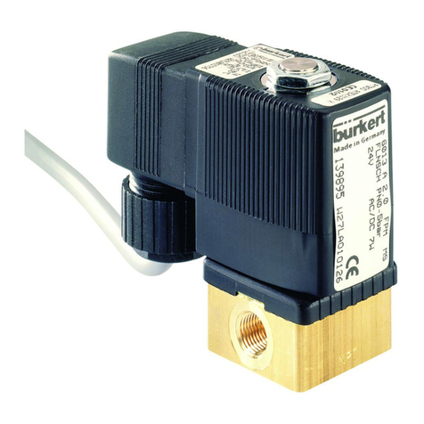
  9. Burkert 0330 User manual

Burkert 0330 User manual

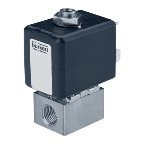
Operating Instructions Type 0330/0331
Design:
The pivoted armature valves are direct acting 2/2 or 3/2-way
solenoid valves in a wide variety of circuit functions. Solenoid
system and media chamber are separated from one another by a
separating diaphragm system
Function:
A
(NC)
2/2-way valve,
closed in rest position
B
(NO)
2/2-way valve,
open in rest position
C
(NC)
3/2-way valve; closed in rest
position, output A unloaded
D
(NO)
3/2-way valve, in rest position, output
B pressurized
E3/2-way mixing valve; in rest position,
pressure connection P2 connected to
output A, P1 closed
F 3/2-way distribution valve, in rest
position, pressure connection P con-
nected to output B
Seal Materials and Fluids handled:
See Table1.
Fluid and Ambient Temperature:
For Hazardous Locations Div. 1 (T4 rated)
Max. Ambient Temperature 104 °F (40 °C)
Max. Fluid Temperature 194 °F (90 °C)
For Hazardous Locations Div. 2 and Ordinary Locations:
See Table1 and 2.
Pressure Range:
Maximum inlet pressure see label on valve.
Manual override:
The manual override can be retained in position if, after depressing
the button, it is turned in a clockwise direction.
Installation:
Type 0330: PTFE tape is recommended for sealing ports.
Mounting is accomplished by means of four M4 x 8 mm tapped
holes located on the valve underside.
Type 0331: Ports A (B) are coded on side of body. For common
pressure, align "A(B)" markings on valve and manifold. Valve ope-
ration C an D valves can be mounted on the same manifold but the
manual override buttons will point in opposite directions.
To remove valve from manifold loosen only the two unsealed
screws. Manifolds can be connected together with nipples.
Blanking plugs, Order No. 0315-1016, should be screwed into
the unused ports. Manifolds can be fixed in position using M5
screws.
Operating Instructions 1511/15_EU-EN_00893144
Assembly instructions: (Fig. 1 : Torque)
The conduit connector on the coil (4) must be supported against
torque during the assembly using appropriate tools (1) (i.e. pliers,
gripper...) (for example a gripper).
While tightening for example a fitting (3) into the conduit connec-
tor attention must be paid to the fact that a max. torque of 20Nm
(177lbf in) is not exceeded.
Fig. 1: Torque
Marking (example):
Body Material
BR = Brass
SS = Stainless steel
PP = Polypropylen
PD = Polyvinyl fluoride
Seal Material
EPDM = EPDM
NBR = NBR
FKM = FKM
Circuit Function
Seal materials with metal valve bodies Seal material with plastic valve bodies
Fluid Temperatures [°F] NBR EPDM FKM NBR EPDM FKM
Air Fluid
Ambient
+ 32 to + 176
+ 32 to + 131
- 22 to + 194
+ 14 to + 131
+ 32 to + 194
+ 32 to + 131
+ 32 to + 122
+ 32 to + 122
- 22 to + 122
+ 14 to + 122
+ 32 to + 122
+ 32 to + 122
Water Fluid
Ambient
+ 41 to + 176
+ 32 to + 131
+ 41 to + 194
+ 14 to + 131
+ 41 to + 194
+ 32 to + 131
+ 41 to + 122
+ 32 to + 122
+ 41 to + 122
+ 14 to + 122
+ 41 to + 122
+ 32 to + 122
Inert
gas
Fluid
Ambient
+ 32 to + 176
+ 32 to + 131
- 22 to + 194
+ 14 to + 131
+ 32 to + 194
+ 32 to + 131
+ 32 to + 122
+ 32 to + 122
- 22 to + 122
+ 14 to + 122
+ 32 to + 122
+ 32 to + 122
Oil Fluid
Ambient - - + 32 to + 194
+ 32 to + 131 - - -
LP-gas Fluid
Ambient - - + 32 to + 194
+ 32 to + 131 - - -
Oxygen Fluid
Ambient - - + 32 to + 194
+ 32 to + 131 - - -
Identity Number
Voltage / Frequency / Power consumption
Maximum Pressure
Approvals
The valve is FM/CSA approved as Explosion Proof valve
for Hazardous Locations
Class I, Division 1, Group A, B, C, D
Class II, Division 1, Group E, F, G
Class III, Division 1 and 2
Operating Temperature T 4
FM approved as Nonincendive for Hazardous Locations
Class I, Division 2, Group A, B, C, D
Class II, Division 2, Group F, G
Class III, Division 1 and 2
Operating Temperature T 4A
CSA approved for Ordinary Locations
UL Recognized and UL Listed for General
Purpose and Fire Protection Services.
See label on the valve.
0330 C 1/8 FKM BR
NPT1/4 PMAX 145PSI
24V DC 8W
00450750 W34ME
Made in Germany
Operating Instructions
Wiring Diagram
Electrical Connection Type 2509
Electrical Connection:
Ensure supply voltage/frequency corresponds with that on label.
Voltage tolerance is ± 10 %.
Available Electrical Connections see “Marking”.
Wiring diagram see above.
For this product to be considered UL-listed and CSA approved
for General Purpose and FM approved for Hazardous Locations
Division 2, it must be in conjunction with the type 2509 cable plug
connector (Electrically Operated Valves Parts, YSYI2).
The connector and gasket must be assembled to the valve with the
screw provided after the connection of the wire leads. This valve
and connector assembly is delivered together and is to be used as
one unit.
For valves to be used in Intrinsically Safe Applications the positive
pole is identified by a “+” on the pin or wire No. 1 has to be con-
nected to the “+”.
See Control Drawing for the Rules of Interconnection.
Warning:
All valves to be used in Intrinsically Safe Applications must be
clearly marked as Intrinsically Safe Apparatus.
Trouble-Shooting:
Check port connections, minimum operating pressure differential
if required and supply voltage. Ensure pilot hole in piston is clear
and pilot bore in the valve outlet is not abstracted. If core does not
pull in, check for short circuit, coil burn-out or foreign matter im-
peding core movement. A jammed or missing core causes the coil
to overheat in the case of AC supply.
Warning:
These products are designed to operate in a wide variety of ap-
plications, it is the user’s responsibility to select a model that is
appropriate for the application. This product is designed to be
installed only by suitably qualified and trained personnel.
Specifications should not be exceeded under any circumstances.
The torque for the terminal screw on type 2509 is 0,5 Nm
(4,4 lbf-in.).
Changes made to this product will render any applicable warranty
null and avoid.
Specifications subject to change without notice.
Any questions? Please call Bürkert Contromatic Technical Service
at (949) 223 31 00.
Power*
Power*
Ground (green dot)
* Orientation is not important
Germany
Contact address:
Bürkert Fluid Control Systems
Sales Center
Chr.-Bürkert-Str. 13-17
D-74653 Ingelfingen
Tel. + 49 (0) 7940 - 10 91 111
Fax + 49 (0) 7940 - 10 91 448
E-mail: [email protected]
International
Contact addresses can be found on the Internet at:
www.burkert.com Bürkert Company Locations

This manual suits for next models

1

Other Burkert Control Unit manuals

Burkert 3364 User manual

Burkert

Burkert 3364 User manual

Burkert 2301 Series User manual

Burkert

Burkert 2301 Series User manual

Burkert 85343 User manual

Burkert

Burkert 85343 User manual

Burkert 0280 User manual

Burkert

Burkert 0280 User manual

Burkert 6013 User manual

Burkert

Burkert 6013 User manual

Burkert 2300 Series User manual

Burkert

Burkert 2300 Series User manual

Burkert 2063 User manual

Burkert

Burkert 2063 User manual

Burkert Type 2000 User manual

Burkert

Burkert Type 2000 User manual

Burkert 1066 User manual

Burkert

Burkert 1066 User manual

Burkert 2030 User manual

Burkert

Burkert 2030 User manual

Burkert 2100 series User manual

Burkert

Burkert 2100 series User manual

Burkert 6516 User manual

Burkert

Burkert 6516 User manual

Burkert 6128 User manual

Burkert

Burkert 6128 User manual

Burkert 2000 INOX User manual

Burkert

Burkert 2000 INOX User manual

Burkert EPS 22 ATEX 1 136 X User manual

Burkert

Burkert EPS 22 ATEX 1 136 X User manual

Burkert 8691 REV.2 User manual

Burkert

Burkert 8691 REV.2 User manual

Burkert 5406 User manual

Burkert

Burkert 5406 User manual

Burkert 6407 User manual

Burkert

Burkert 6407 User manual

Burkert 3320 User manual

Burkert

Burkert 3320 User manual

Burkert 8695 Series User manual

Burkert

Burkert 8695 Series User manual

Burkert 6211 Instruction Manual

Burkert

Burkert 6211 Instruction Manual

Burkert Type 2000 User manual

Burkert

Burkert Type 2000 User manual

Burkert 2030 User manual

Burkert

Burkert 2030 User manual

Burkert 2100 series User manual

Burkert

Burkert 2100 series User manual

Popular Control Unit manuals by other brands

RWC TMV2 Installation and maintenance instructions

RWC

RWC TMV2 Installation and maintenance instructions

Keysight 34959A user guide

Keysight

Keysight 34959A user guide

Inta Intamix Pro 60001CP Installation and maintenance instructions

Inta

Inta Intamix Pro 60001CP Installation and maintenance instructions

Enerpac PRV2 instruction sheet

Enerpac

Enerpac PRV2 instruction sheet

Siemens MJ-XL installation manual

Siemens

Siemens MJ-XL installation manual

pizzato CS ME-30 Series quick start guide

pizzato

pizzato CS ME-30 Series quick start guide

SEA USER 1-24V manual

SEA

SEA USER 1-24V manual

GST DI-M9300 manual

GST

GST DI-M9300 manual

Pulsar MPSB12 manual

Pulsar

Pulsar MPSB12 manual

Almot 870N Instruction manual and use

Almot

Almot 870N Instruction manual and use

Imi Heimeier V-exact II quick start guide

Imi Heimeier

Imi Heimeier V-exact II quick start guide

Utopia 360 ETVRREM quick start guide

Utopia 360

Utopia 360 ETVRREM quick start guide

SMC Networks VFS Series manual

SMC Networks

SMC Networks VFS Series manual

janitza 800-CON User manual and technical data

janitza

janitza 800-CON User manual and technical data

Parker EP Series Pro-Bloc Installation and operation manual

Parker

Parker EP Series Pro-Bloc Installation and operation manual

HWH 625 Series Operator's manual

HWH

HWH 625 Series Operator's manual

Bardiani Valvole J-GIOTTO TOP Instruction, use and maintenance manual

Bardiani Valvole

Bardiani Valvole J-GIOTTO TOP Instruction, use and maintenance manual

SmartOne 70-600000-001 installation instructions

SmartOne

SmartOne 70-600000-001 installation instructions

manuals.online logo
manuals.online logoBrands
  • About & Mission
  • Contact us
  • Privacy Policy
  • Terms and Conditions

Copyright 2025 Manuals.Online. All Rights Reserved.