Installation
Page/Seite/Page 8 © Edwards Limited 2007. All rights reserved.
Edwards and the Edwards logo are trademarks of Edwards Limited.
C417-21-885 Issue B/Ausgabe B/Version B
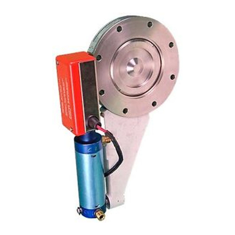
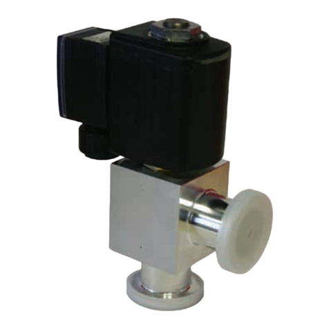
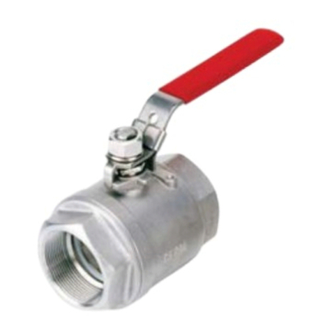
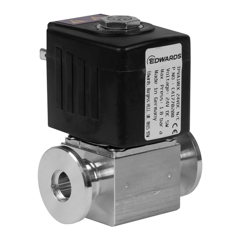
Connect the valve to your vacuum system (and, if
required, to your vent gas supply) with standard NW
coupling components.
To achieve the MTTF stated in Section 2, you must fit the
valve so that the actuator is horizontal or above the
valve body.
If you will use the valve to vent directly from the
atmosphere, we recommend that you fit a filter to the
inlet of the valve to prevent blockage of the valve by
dust.
3.3 Electrical connections
Note: Refer to Figure 2. The electrical supply socket
(3) can be orientated through 360°, in steps of
90°, with respect to the connector block (2).
After you have passed the electrical supply
cable through the socket, turn the socket to the
required orientation before you refit it to the
connector block.
Refer to Figure 2 for item numbers in brackets and use
the following procedure to connect the electrical supply
to the valve; ensure that you use a suitable size
electrical supply cable (refer to Section 2.3):
1. Check that the electrical supply corresponds with
the voltage stated on the valve label.
Ensure that the electrical installation of
the IPVA10EK valve conforms with your
local and national safety requirements. It
must be connected to a suitable fused
and protected electrical supply.
Auf dem Ventilkörper befindet sich ein Pfeil, der die
Richtung des Gasflusses angibt. Bei Umkehrung des
Gasflusses kann es zu Lecks im Ventil kommen.
Das Ventil so an das Vakuumsystem anschließen, daß der
Pfeil von der Atmosphäre (bzw. der Zuleitung für das
Belüftungsgas) zum Vakuumsystem hin zeigt.
DerAnschluß desVentils andasVakuumsystem(undggfs.
die Zuleitung für das Belüftungsgas) erfolgt mit
standardmäßigen NW-Flanschteilen.
Damit die in Abschnitt 2 genannte mittlere Lebensdauer
erzielt werden kann, muß das Ventil so eingebaut
werden, daß das Stellgliedhorizontal oder oberhalb des
Ventilkörpers liegt.
Wird das Ventil zur direkten Belüftung aus der
Atmosphäre verwendet, empfiehlt sich der Einbau eines
Filters in den Einlaß. Auf diese Weise wird ein Verstopfen
des Ventils durch Staubpartikel verhindert.
3.3 Elektrische Anschlüsse
Unbedingt darauf achten, daß der
elektrische Einbau des Ventils IPVA10EK
den örtlichen und nationalen
Sicherheitsvorschriften entspricht. Der
Anschluß muß über eine geeignete mit
Sicherung versehene und geschützte
Netzversorgung erfolgen.
Brancher la vanne sur le système de vide en s’assurant
que cette flèche respecte le sens suivant : de
l’atmosphère (ou de votre alimentation en gaz) vers le
système de vide.
Brancher la vanne sur votre système de vide (et, le cas
échant, sur votre alimentation en gaz) en utilisant des
brides NW standard.
Pour obtenir la durée de vie indiquée la Section 2,
l’actionneur de la vanne doit être à l’horizontal ou au-
dessus du corps de la vanne.
Si vous utilisez cette vanne pour effectuer une mise à
l’air libre directe, nous vous recommandons d’installer
un filtre à l’entrée de cette vanne pour éviter le
colmatage de cette dernière par de la poussière.
3.3 Branchements électriques
Attention : Reportez-vous au schéma 2. La prise
d’alimentationélectrique(3)peutpivoter
de 360° par rapport au bloc connecteur
(2), par paliers de 90°. Après avoir fait
passer le câble d’alimentation électrique
dans la prise, donnez-lui l’orientation
désirée avant de la réintégrer au bloc
connecteur.
L’installation électrique de la vanne
IPVA10EK doit respecter les normes de
sécurité locales et nationales. Elle doit
être reliée à une alimentation électrique
correcte protégée et équipée d’un
fusible.


