AMSAN AM-TPL12CF User manual

PLEASE READ THE PRODUCT MANUAL ENTIRELY BEFORE INSTALLING OR
OPERATING THE LIFT.

Two Post Car Lift AM-TPL12CF
2
IMPORTANT INFORMATION
•The shipment should be thoroughly inspected as soon as it is received. Any freight
damage or missing items must be noted on the freight bill before signing and reported
to the freight carrier with a freight claim established. The buyer should claim
compensation from the freight carrier if any damage happens to the equipment during
shipping. Please refer to our website for detailed shipping policies and procedures.
•Make sure you have additional help or heavy-duty lifting equipment when unloading and
assembling the lift.
•Read and understand this installation and operation manual entirely before attempting
to install or operate the lift. Keep this manual near the product for future references.
Make sure all operators read this manual.
•The lift should only be operated by authorized personnel. Keep children and untrained
personnel away from the lift.
•Do not make any modifications to the Lift; this voids the warranty and increases the
chances of injury or property damage. •
•Do not use the lift while tired or under the influence of drugs, alcohol, or medication
•The manufacturer or distributor assumes no responsibility for loss or damage of any
kind, expressed or implied, resulting from improper installation or use of this lift. Always
use professional installation companies.
•All persons using the equipment must be responsible, qualified, and carefully follow the
operation and safety guidelines contained in this manual.
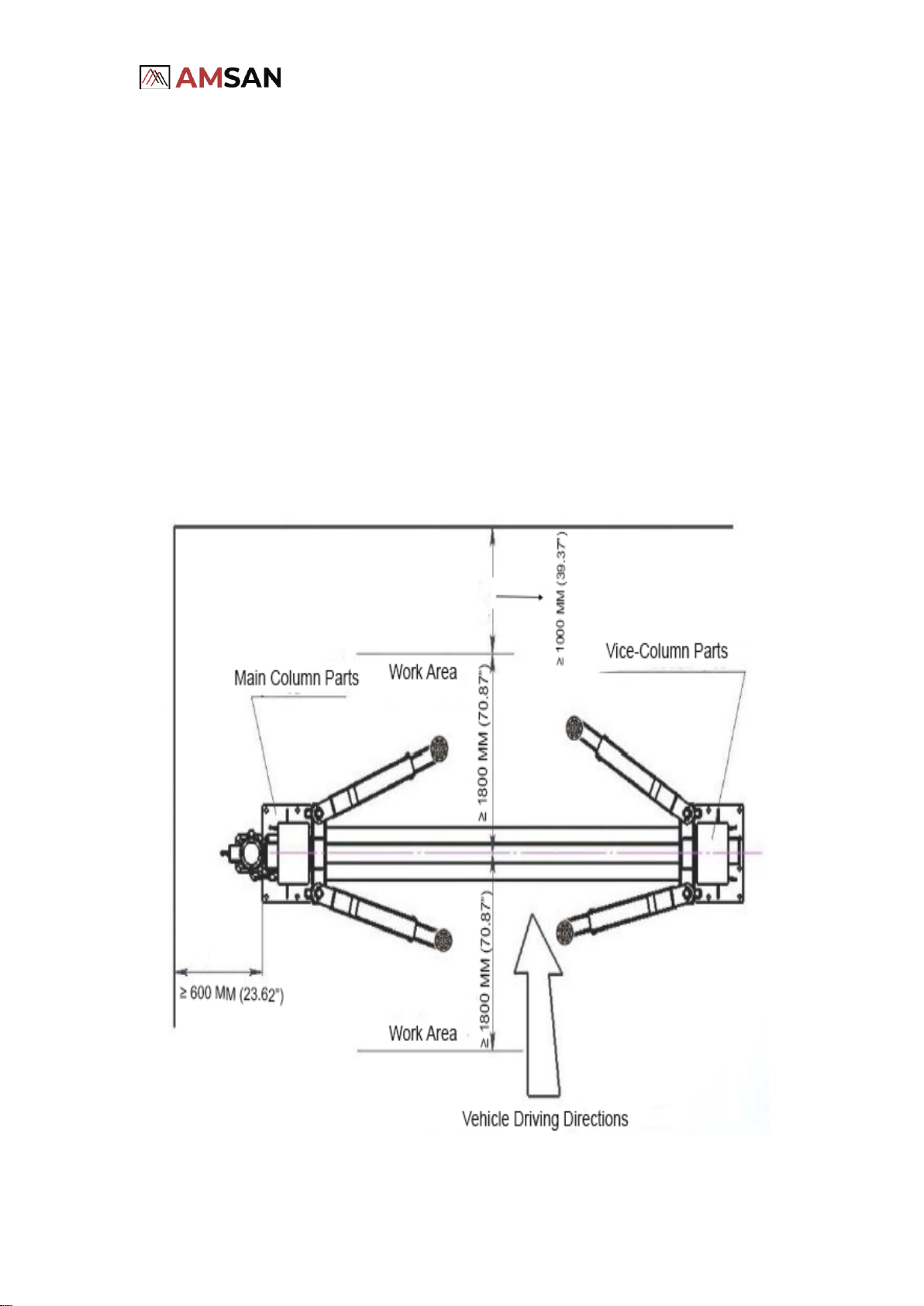
•A level floor is required for proper lift installation and operation.
•DO NOT install this lift on any asphalt surface. Lift must be installed on the concrete
surface a minimum of 12” thick and 3,000 psi tensile strength with steel or fiber mesh.
Reinforcement. New concrete must be adequately cured by at least 28 days minimum.
•DO NOT install this lift over concrete expansion joints or cracks. (Consult with your
building engineer)
•DO NOT install this lift on the upper floor without written authorization from your
building engineer. Should only be installed on the ground floor without a basement.
•DO NOT attempt to lift only part of a vehicle. This lift is intended to raise the entire body
of a vehicle only. This will bend the arms and void the warranty.
•NEVER lift any persons or vehicles containing persons. This lift is designed to lift empty
vehicles only.
•Any vehicle whose weight is above 12,000lb is not allowed to be raised on this machine.
•All wiring must be performed by a licensed, certified Electrician.
•Do not perform any maintenance until the main electrical power has been disconnected
from the lift and cannot be re-energized until all procedures are complete.
•All information in this manual is believed to be correct at the time of publication. The
design, material, and specifications are subject to change without notice.

Two Post Car Lift AM-TPL12CF
3
TABLE OF CONTENTS
Contents
TABLE OF CONTENTS................................................................................................................................. 3
SAFETY INSTRUCTIONS AND CAUTIONS........................................................................................................... 4
CAUTION SIGNS....................................................................................................................................... 4
SAFETY CAUTION SIGNALS ........................................................................................................................ 5
LIFTING CAPACITY ................................................................................................................................... 6
SAFETY CHECK POINTS ............................................................................................................................. 6
LIFT COMPONENTS....................................................................................................................................... 7
LIFT DIMENSIOINS ....................................................................................................................................... 8
TECHANICAL SPECIFICATIONS....................................................................................................................... 9
INSTALLATION........................................................................................................................................... 10
SPACE REQUIREMENTS ........................................................................................................................... 10
FOUNDATION REQUIREMENTS .................................................................................................................. 11
ANCHORING GUIDELINES ........................................................................................................................ 12
TOOLS RECOMMENDED ........................................................................................................................... 13
INSTALLATION INSTRUCTIONS ................................................................................................................. 13
OPERATION .............................................................................................................................................. 20
MAINTENANCE........................................................................................................................................... 21
DAILY INSPECTION................................................................................................................................. 21
MONTHLY INSPECTION............................................................................................................................ 22
EVERY 6 MONTH INSPECTION .................................................................................................................. 22
TROUBLE SHOOTING .................................................................................................................................. 23
HYDRAULIC DRAWING................................................................................................................................ 25
EXPLODED DRAWING.................................................................................................................................. 26
MAINTENANCE LOG .................................................................................................................................... 28

Two Post Car Lift AM-TPL12CF
4
SAFETY INSTRUCTIONS AND CAUTIONS
CAUTION SIGNS
Danger! Pay special attention to this symbol as it
means unsafe or hazardous practices that can
lead to severe personal injury or death or damage
to the lift or property.
Caution! Read and follow the instructions next to
this symbol to avoid big casualties and heavy
damage to the lift.
Attention! The section besides this signal lists the
notice points and security requirements during
the process of normally using and maintaining the
lift.

Two Post Car Lift AM-TPL12CF
5
SAFETY CAUTION SIGNALS
Please read Safety Signage carefully, understand, and
remember them.

Two Post Car Lift AM-TPL12CF
6
LIFTING CAPACITY
Rated Load
AM-TPL12CF
12,000LB
SAFETY CHECKPOINTS
•Operators should read the manual carefully to avoid accidents.
•Operators should be familiar with all functions and operating methods
of the lift.
•Check before operating and regular checks must be carried out too.
•If there is any abnormal sound during raising and lowering, stop using
the lift.
•Never use the lift to raise the vehicle whose weight is above 12,000lb.

Two Post Car Lift AM-TPL12CF
7
LIFT COMPONENTS
Crossbeam
Limit device
Safety
wheel
Steel
cable
Main
post
Swing arm
Cable
Sheave
Power
unit
Rubber Pad
Safety
cover
Sub
post

Two Post Car Lift AM-TPL12CF
8
LIFT DIMENSIONS

Two Post Car Lift AM-TPL12CF
9
TECHANICAL SPECIFICATIONS
Overall Height
146.1"
Time to Full Rise/Drop
50 seconds
Maximum Lifting Height
76.8”
Minimum Height of Rubber Pads
3.9”
Adjusting Range of Arm
28.2”- 42.1” and 32.1” –62.6”
Width Between Posts
116.1”
Overall Width
142.1”
Power Unit
220 VAC / 1PH / 60HZ
Noise Level
≤75dB(A)
Drive Through Clearance
104.5”
Width of Posts from Outside
142.1”
The design, material, and specifications are subject to change without notice.

Two Post Car Lift AM-TPL12CF
10
INSTALLATION
SPACE REQUIREMENTS
•You must consult the architectural plans for the desired location. Make sure
there are no contradictions between how you want to build and how the
plans indicate.
•The area where the lift will be located should be free of overhead obstructions
such as heaters, building supports, electrical wires, and so on. Also, make there
is enough clearance around the lift for driving vehicles getting on or off the lift.
Please refer below for exact measurements.

Two Post Car Lift AM-TPL12CF
11
FOUNDATION REQUIREMENTS
•Visually inspect the site where the lift is to be installed and check for cracked
or defective concrete
•DO NOT install or use this lift on expansion seams or cracked or defective
concrete.
•DO NOT install or use this lift on any asphalt surface or any surface other than
concrete.
•Lift is designed for INDOOR INSTALLATION ONLY.
•This lift must be installed on a solid level concrete floor with no more than 3-
degrees of slope.
•Lift buyers are responsible for any special regional structural and/or seismic
anchoring requirements specified by any other agencies and/or codes such as
the Uniform Building Code (UBC) and/or International Building Code (IBC).
•All models MUST be installed on 3000 PSI concrete and have a minimum of 12”
thickness with steel or fiber mesh. New concrete must be adequately cured by
at least 30 days minimum.
Installation area picture (See figure below.)

Two Post Car Lift AM-TPL12CF
12
ANCHORING GUIDELINES
•Please carefully remove all the parts from the package.
•Use a concrete rotary hammer drill with a 3/4” drill bit. Do not use excessively
worn or incorrectly sharpened drill bits.
•Keep the drill in a vertical position when drilling. Do not apply excessive
pressure and let the drill do the work. Try to lift the drill sporadically and clean
residue in the hole. Power blow dust from the hole for better holding.
•Drill the holes 1.25" deeper than the length of the anchor bolts. Try to drill
through the concrete so that when you move the lift to a new location, you may
hammer down the anchor bolts instead of cutting them off.
•Assemble the washers and nuts onto the anchor bolts. Thread the nuts onto
the anchor bolts where the tops of the nuts are just above the top of the bolts,
as shown in the figure below. Using a hammer, carefully tap the anchor bolts
into the concrete until the washer rests against the baseplate. Do not damage
the nuts or threads. Try not to use an impact wrench to tighten the nut. Tighten
the nut two or three turns after the concrete is cured (30-day minimum cure).
In the case where the concrete is very hard, tighten only one or two turns.
Check the following diagram for the footprint of columns with anchor bolts
positions.

Two Post Car Lift AM-TPL12CF
13
TOOLS RECOMMENDED
⚫Chalk Line
⚫
⚫4 Foot Level
⚫Set of Metric Wrenches/Sockets
⚫
⚫Flat Screwdriver
⚫Adjustable Wrench
⚫
⚫Hex-Key / Allen Wrench Set
⚫Locking Pliers
⚫
⚫Needle Nose Pliers
⚫Tape Measure
⚫
⚫Rotary Hammer Drill
⚫Step Ladder
⚫
⚫3/4" Masonry Bit
⚫Hammer
⚫
⚫3 Gallons of Hydraulic Oil*
⚫Crow Bar
⚫Forklift
⚫
*Recommended Oil: ISO 32, ISO 46 Hydraulic Oil or Dexron III ATF
INSTALLATION INSTRUCTIONS
ONLY TRAINED INSTALLERS SHOULD PERFORM LIFT INSTALLATION WORK.
Step 1.
•Please remove all the packaging and then remove the power unit from the top.
•Remove shipping racks from both sides by removing the bolts. Please see the
picture below.

Two Post Car Lift AM-TPL12CF
14
•After removing the shipping racks holding the two columns together, remove
both posts out of the skid and discard the steel racks. Remove all the parts.
•Please make sure you read the space, foundation, and installation
requirements and anchoring guidelines thoroughly in previous pages. The area
where the lift will be located should be free of overhead obstructions such as
heaters, building supports, electrical wires, and so on. Also, make there is
enough clearance around the lift for driving vehicles getting on or off the lift.
•By using chalk, draw an outline of the base plate on the installation ground
and establish the position for the two posts
•Double-check all dimensions and make sure that the layout is square.
Step 2.
•Ascertain the side where the power unit post will be located. Please remember
this is the post where your main electrical power supply will be connected. It is
highly recommended to locate the power side with the passenger side of the
vehicle when loaded on the lift to save steps during operation.
•Double-check all dimensions and make sure that the layout is square.
and aligned with the chalk line.
•Stand up the power unit post (this post has the power unit bracket welded on)
and position it inside the chalked lines. Position the post toward the other
post. Please see the picture below.
•Now stand up the other post opposite to the main power unit post inside the

Two Post Car Lift AM-TPL12CF
15
chalk lines as shown in the picture in the last step.
•Drill the anchor holes only for one post with a 3/4-inch drill bit into concrete
following the Anchoring guideline under the anchoring guideline section.
•The second post will be anchored after the cables, hoses, and top crossbar are
installed.
•Use a 4-feet leveler to check the level of each base plate. Place shims under the
base plate as needed.
•Tighten all the anchor bolts and recheck for level.
•Hammer down the anchor bolts all the way and then tighten them using a
torque wrench. Avoid using an impact wrench when tightening the anchor
bolts.
Step 3.
•Now bolt the overhead beam to both posts. To avoid interference with the
cables when running the lift, be sure to bolt them together from the inside of
the beam.
Step 4.
•Raise the sliding carriage on each column to the height of about 23” to 32”,
then drop it to the safety latch stops and make sure it will not fall again.
•See the top of the carriage where you will find two holes.
•Run the cables as shown below.
•Secure the second post by anchoring it down as described in previous steps.

Two Post Car Lift AM-TPL12CF
16

Two Post Car Lift AM-TPL12CF
17
Step 5.
Locking Latch Cable
•Release Cable Connecting Picture
Step 6.
•Mount the power unit onto the power side post using bolts and nuts.
•Connect two fittings to both cylinders and Connect T-fitting to the power unit.
•Connect the long hydraulic hose to the power unit and the cylinder in the
opposite post by running the long hose over the overhead bar. Connect the
short hydraulic hose to the power unit and the cylinder in the power unit post.
•Run the hoses as shown below.

Two Post Car Lift AM-TPL12CF
18
Step 7.
•Install four arms to both posts respectively. Swing the arms to make sure they
are installed properly. Install the arm locking parts.
Step 8.
•For wiring the power unit, please consult with a certified electrician to connect
the power unit to a power outlet.

Two Post Car Lift AM-TPL12CF
19
Step 9.
•Double-check all the nuts and bolts, make sure they are tight and secure.
Adjust tensions to cable equally. NEVER OVER TIGHTEN the fittings.
Step 10.
•Fill hydraulic oil in the power unit reservoir about 10 liters. Recommended Oil:
ISO 32, ISO 46 Hydraulic Oil or Dexron III ATF
Step 11.
•Connect the power. Connect the power according to the pictures on the
nameplate. It is required to set a power switch beside the lift, to cut off the
power to maintain the equipment or cope with the emergency.
Step 12.
•Lubricate the slide rails inside the two columns.
Step 13.
•Test the lift with an empty load. Check the tension in the chains and make sure
the two columns are moving together. Please check cables regularly for equal
tension.
Step 14.
•Test the lift with the heavy load. Check whether the hydraulic system is
working normally
Step 15. Bleed out the Air from Cylinders
•Place a vehicle on the lift and raise until arm pads are in contact with the
frame of the vehicle. Raise the vehicle about 4 feet and then bring it down until
the tires touch the floor. Keep doing this process a few times and increase the
height each time until the vehicle completely reaches the top. With this
process, all the air will be pumped out. Lifting speed will be faster after air is
bled out.

Two Post Car Lift AM-TPL12CF
20
OPERATION
Please read the operation manual carefully before operating the lift. Only
authorized technician should be operating the lift.
•Clear the area immediately, if the Vehicle on the lift is suspected of falling.
•Do not operate a lift that is damaged or in need of repair.
Raising the lift
•Position vehicle between posts.
•Place pads at vehicle manufacturer’s recommended pickup points.
•Raise the lift by pressing the Push-up switch until tires clear the floor. Recheck
if the vehicle is secure and if all is good then raise the lift to your desired
height.
•Always lower the vehicle lift into the nearest lock position by pressing the lower
lever to relieve the hydraulic pressure. After that let the latch set in a locking
position.
•DO NOT work under a vehicle lift when the lift is not in a locking position.
Lowering the lift
•Make sure the area is clear under the vehicle lift before bringing the lift down.
•Raise the lift of the safety locks by a couple of inches and then release the
safety device, lower the vehicle by pushing the lowering handle.
•Unload the lift by completely lowering the lift and then swing the arms to drive
through position before moving the vehicle.
•Please note: To increase the service life of the cylinder and seal, the vehicle lift
needs to be raised to the highest position at least once a day.
Table of contents
Other AMSAN Lifting System manuals