TECNOMAGNETE Bat-Grip 300/N Series User manual

USE AND MAINTENANCE MANUAL
MANUALE USO E MANUTENZIONE
®
S.p.A.
Via Nerviano, 31 - 20020 Lainate (Mi) - ITALIA
Tel. +39-02.937.591 R.A. - Fax. +39-02.935.708.57
Rev. B IT/GB DEL 01/2010
®
SOLLEVATORE A BATTERIA
MANUALE USO E
MANUTENZIONE
MANUALE USO E
MANUTENZIONE
Page 2 of 27 ®
USE AND MAINTENANCE
MANUAL
USE AND MAINTENANCE
MANUAL
NOTEGENERALI
Ci complimentiamo con Voi per aver scelto un
prodotto della Ditta TECNOMAGNETE S.p.A.
QuestapubblicazioneViaiuteràaconosceremeglio
la vostra apparecchiatura.
Viraccomandiamopertantodileggereattentamente
queste pagine e seguirne sempre i consigli.
Per qualsiasi richiesta o informazione riguardante
l’apparecchiatura mettersi in contatto con il servizio
assistenza TECNOMAGNETE S.p.A.
(tel. +39-02.937591.207).
IMPORTANZA DEL MANUALE
Considerare il MANUALE USO E MANUTENZIONE
come parte integrante della macchina.
Custodireilmanualepertuttalavitadellamacchina.
Assicurarsichequalsiasidocumentopervenutoven-
ga incorporato con il manuale.
Passare il manuale a qualsiasi altro utente o suc-
cessivo proprietario della macchina.
CONSERVAZIONE DEL MANUALE
Impiegare il manuale in modo tale da non danneg-
giarne il contenuto.
Non asportare, strappare, o riscrivere per alcun
motivo parti del manuale.
Conservare il manuale in zone protette da umidità e
calore.
Le descrizioni e le illustrazioni contenute nella pre-
sente pubblicazione si intendono non impegnative.
Ferme restando le caratteristiche essenziali del tipo
di apparecchiartura descritta, la TECNOMAGNETE
S.p.A. si riserva il diritto di apportare le eventuali
modifiche di organi, dettagli e accessori, che riterrà
opportuno per il miglioramento del prodotto o per
esigenze di carattere costruttivo o commerciale, in
qualunque momento e senza impegnarsi ad aggior-
nare tempestivamente questa pubblicazione.
La società TECNOMAGNETE S.p.A. si riserva la
proprietà di questo manuale e ne vieta la riproduzio-
ne anche parziale e la possibilità di renderlo noto a
terzi senza la Sua autorizzazione scritta.
GENERALINFORMATION
We want to thank you for choosing one of
TECNOMAGNETE’s S.p.A. products.
This manual will help you to improve your knowledge
of the machine, so read carefully the following pages
and always observe advices.
For further information about the machine, please
call TECNOMAGNETE S.p.A. customer care
service.
(tel. +39-02.937591.207).
IMPORTANCE OF THIS MANUAL
The following USE AND MAINTENANCE MANUAL
is to be considered as an integral part of the
machine.
It should be kept throughout the machine lifetime.
Makesurethatanydocument relevanttothe machine
is enclosed with the manual.
If the machine should be resold, hand this manual
over to the new machine owner.
MANUAL PRESERVATION
Use this manual correctly in order not to damage it.
Do not remove, tear or rewrite any page of this
manual .
Keep it in a safe area, away from heat and humidity
sources.
The descriptions and illustrations in the manual are
not to be considered as binding.
Although the main features of the machine described
in this manual are not subject to change,
TECNOMAGNETE S.p.A. reserves the right to
change those components, details and accessories
it deems neccessary to improve the machine or meet
manufacturing or commercial requirements, at any
time and without updating this manual immediately.
This manual is property ofTECNOMAGNETES.p.A.
The reproduction of any part of it, in any given form,
withoutprior writtenauthorizationof themanufacturer,
is strictly forbidden.

USE AND MAINTENANCE
MANUAL
MANUALE USO E
MANUTENZIONE
MANUALE USO E
MANUTENZIONE USE AND MAINTENANCE
MANUAL
Page 3 of 27
®
PRESENTAZIONE
DELLA SOCIETA’
TECNOMAGNETE inizia la sua attività nel 1972 come
produttore di sistemi magnetici elettropermanenti
capaci di operare con potenza, flessibilità ed in totale
sicurezza e grazie alla sua tecnologia innovativa ed a
numerosi brevetti depositati nel corso degli anni, ha
conquistato una posizione di leadership su numerosi
mercati mondiali.
Isistemi magnetici elettro-permanentiTecnomagnete
sono in grado di generare tutta la forza di attrazione
magnetica necessaria sia per l’ancoraggio che per il
sollevamento di pezzi, senza necessità di utilizzare
energia elettrica durante le fasi di lavoro.
I principali settori di attività comprendono:
DIVISIONE “SOLLEVAMENTO”
- Sollevatori elettropermanenti MTE per la
movimentazione di qualsiasi tipologia di carico
ferroso.
- Sollevatori elettro-permanenti BAT-GRIP con
batteria incorporata
- Sollevatori a comando manuale MaxX
SEZIONE ANCORAGGIO MACCHINE UTENSILI
- Piani QUADRISISTEMA, destinati ad attrezzare
fresatrici e centri di lavoro di ogni dimensione
- Piani TFP per rettifiche di alta precisione
- Piani RADIAL-POLE per operazioni di finitura o
sgrossatura su torni verticali
- Moduli QUAD-RAIL per l’ancoraggio di rotaie di
qualsiasi lunghezza
- Piani MDS per macchine elettro-erosione a tuffo.
SEZIONE ANCORAGGIO PRESSE
- Sistemi QUAD-PRESS, per l’ancoraggio di stam-
pi.
Grazie alla vasta gamma delle soluzioni proposte,
alla flessibilità ad adattarsi alle esigenze del clien-
te, alla tecnologia d’avanguardia, ad un efficiente
servizio pre-post vendita, TECNOMAGNETE ha sa-
puto realizzare in oltre un ventennio di attività circa
50.000 installazioni in tutto il mondo.
COMPANY
OUTLINES
Since 1972 TECNOMAGNETE has been
manufacturing magnetic electropermanent systems
characterized by powerful, flexible and totally safe
performances. Thanks to its innovative technology
and design patents, filed throughout this period of
time, the company has become a worldwide leading
reference point.
Tecnomagnete’s magnetic electropermanent
systems are able to generate the magnetic attractive
force necessary to retain or lift loads, without the
use of electric power during work stages.
The main activity areas are:
“LIFTING” DIVISION
- MTE Electro-permanent lifting units for any type
of steel handling.
- BAT-GRIP electro-permanent lifting units with
built-in battery.
- MaxX lifting units with manual control.
MACHINE TOOLS ANCHORING DIVISION
- QUADRISYSTEM chucks, to equip millers and
working centres of all sizes
- TFP chucksfor high accuracy grinding
- RADIAL-POLE chucks for finishing or rough
machining operations on vertical turning lathes.
- QUAD-RAIL modulesto anchor rails of any length
- MDS chucksfor plunge spark erosion machines.
PRESS ANCHORING DIVISION
- QUAD-PRESS systems, for mould anchoring.
TECNOMAGNETE has installed about 50.000
plants all over the world in over twenty years of activity
thanks to the wide range of solutions offered, thanks
to the capacity of adapting to our customer’s needs,
thanks to the state of the art technology and thanks
to an efficient customer pre/post sale service.
MANUALE USO E
MANUTENZIONE
MANUALE USO E
MANUTENZIONE
Page 4 of 27 ®
USE AND MAINTENANCE
MANUAL
USE AND MAINTENANCE
MANUAL
NOTE GENERALI..................................2
PRESENTAZIONE DELLA SOCIETA’.........3
0PREMESSA...................................5
GARANZIA.......................................6
1TRASPORTO E
MOVIMENTAZIONE...........................7
2 DESCRIZIONE DEL SISTEMA............8
2.1 PRINCIPIO DI FUNZIONAMENTO DEL
CIRCUITOTECNOMAGNETE.................8
2.2 DATIDITARGA.........................................10
2.3 CARATTERISTICHE GENERALI..........11
2.4 CARATTERISTICHETECNICHE...........13
3INSTALLAZIONE......................14
3.1 VERIFICA DEL PRODOTTO
ACQUISTATO.........................................14
3.2 ALLACCIAMENTO ELETTRICO.......14
4 PROTEZIONI E SICUREZZA.........15
4.1 AVVERTENZE................................15
4.2 NORME DI SICUREZZA.....................16
4.3 DISPOSITIVO DAUTANAC................17
5 USO NORMALE................................18
5.1 PULSANTIERE..............................18
5.2 ISTRUZIONI PER L’OPERATORE.....19
6 MANUTENZIONE......................20
6.1 PREMESSA...................................20
6.2 NORME DI SICUREZZA DURANTE
LA MANUTENZIONE......................20
6.3 PARTE MECCANICA.....................21
6.4 IMPIANTO ELETTRICO.................21
6.5 ELENCO PARTI DI RICAMBIO........22
6.6 ASSISTENZA TECNICA................23
6.7 SCHEDA REG. INTERVENTI..........24
7 SMANTELLAMENTO..................25
7.1 IMMAGAZZINAMENTO...................25
7.2 MESSA FUORI SERVIZIO..............25
GENERAL INFORMATION.....................2
COMPANY OUTLINES...........................3
0FOREWORD...................................5
WARRANTY....................................6
1TRASPORTATION AND
HANDLING..........................................7
2 SYSTEM DESCRIPTION..............8
2.1 TECNOMAGNETE’S CIRCUIT
OPERATINGFUNCTION.........................8
2.2 IDENTIFICATION DATA..................10
2.3 GENERAL CHARACTERISTICS.........11
2.4 TECHNICAL FEATURES............13
3INSTALLATION.................................14
3.1 INSPECTION OF PURCHASED
PRODUCT..........................................14
3.2 ELECTRIC CONNECTION...............14
4 PROTECTION DEVICES AND
SAFETY RULES.......................15
4.1 GENERAL INFORMATION.............15
4.2 SAFETY RULES.............................16
4.3 DAUTANAC DEVICE.......................17
5 NORMAL USE................................18
5.1 PUSH-BUTTON PANELS..............18
5.2 OPERATING INSTRUCTIONS......19
6 MAINTENANCE........................20
6.1 FOREWORD....................................20
6.2 SAFETY RULINGS DURING
MAINTENANCE.................................20
6.3 MECHANICS..................................21
6.4 ELECTRIC SYSTEM.......................21
6.5 SPARE PART LIST.........................22
6.6 TECHNICAL ASSISTANCE.............23
6.7 OPERATION SCHEDULE.............24
7 DISMANTLING..........................25
7.1 STORING.......................................25
7.2 DISPOSAL OF EQUIPMENT.............25
INDICE CONTENTS

USE AND MAINTENANCE
MANUAL
MANUALE USO E
MANUTENZIONE
MANUALE USO E
MANUTENZIONE USE AND MAINTENANCE
MANUAL
Page 5 of 27
®
0PREMESSA
L'apparecchiatura descritta nel presente
manuale è conforme, in ogni sua parte alle
seguenti normative:
+
EN 12100-1: Sicurezze del macchinario -
Concetti fondamentali, terminologia,
metodologia di base
+
EN 12100-2: Sicurezze del macchinario -
Concetti fondamentali - Specifiche e
principi tecnici
+ DR 2006/42/CE : Direttiva macchine
ATTENZIONE
La configurazione originale della macchi-
na non deve essere assolutamente modi-
ficata.
L'utilizzodellamacchinaperlavorazionidiver-
se da quelle indicate dal costruttore può cau-
saredannoall'attrezzaturaepericoloperl'ope-
ratore.
Per lavorazioni di materiali speciali diversi da
quelli indicati nel presente manuale, deve es-
sere preventivamente richiesto il consenso al
costruttore stesso.
SIMBOLOGIA IMPIEGATA
Le operazioni che, se non effettuate corretta-
mente, possono presentare rischi, sono indi-
cate con il simbolo:
Le operazioni per la cui esecuzione si richie-
de, onde evitare possibili rischi, personale
qualificato o specializzato sono evidenziate
con il simbolo:
0FOREWORD
The machinery described in this manual
complies, in all its parts, with the following
standards:
+
EN 12100-1: Machine safety - Fundamental
concepts, terminolgy, basic
methodology
+
EN 12100-2: Machine safety - Fundamental
concepts - Technical specifications and
principles
+ DR 2006/42/CE : Machine directive
WARNING
The machine original configuration must
not be modified in any way.
Using the machine in a different way than the
one indicate by the manufacturer can damage
the equipment and injure the operator.
In order to use the machine with different and
special materials the operator should obtain
the manufacturer’s authorization.
SYMBOLS USED
Those operations which might be dangerous
if not performed correctly are indicated with the
following symbol:
Those operations which, in order to avoid risks,
must be performed by trained and
authorized personnel are indicated by the
following symbol:

MANUALE USO E
MANUTENZIONE
MANUALE USO E
MANUTENZIONE
Page 6 of 27 ®
USE AND MAINTENANCE
MANUAL
USE AND MAINTENANCE
MANUAL
GARANZIA
I prodotti TECNOMAGNETE sono garantiti per la du-
rata di 24 mesi dalla data della fattura, salvo diversi
accordi scritti. La garanzia copre tutti i difetti dei mate-
riali e di fabbricazione e prevede sostituzioni di parti di
ricambiooriparazionidei pezzi difettosi esclusivamente
a nostra cura e presso la nostra officina.
Il materiale in riparazione dovrà essere inviato in POR-
TO FRANCO.
A riparazione avvenuta l’apparecchiatura sarà inviata
in PORTO ASSEGNATO al cliente.
La garanzia non prevede l'intervento di nostri operai o
addetti sul posto di installazione l’apparecchiatura né
il suo smontaggio dall'impianto. Nel caso che per esi-
genze pratiche sia inviato un nostro addetto, la presta-
zione di manodopera sarà fatturata ai prezzi correnti
più eventuale trasferta e spese di viaggio.
In nessun caso la garanzia dà diritto a indennità su
eventuali danni diretti o indiretti causati dalle nostre
macchine a cose o persone o su interventi di riparazio-
ne effettuati dal compratore o da terzi.
Sono esclusi dalla garanzia:
+guasti causati da utilizzo o montaggio non corret-
to.
+danni causati da utilizzo di parti di ricambio diver-
se da quelle consigliate
+danni causati da incrostazioni.
DECADENZA DELLA GARANZIA:
+in caso di morosità o altre inadempienze contrat-
tuali;leriparazionieffettuateingaranzianoninter-
rompono il periodo della stessa
+qualora fossero fatte, senza nostro consenso, ri-
parazioni o modifiche alle nostre macchine
+quando il n° di matricola sia stato manomesso o
cancellato
+quando il danno sia causato da un funzionamen-
to o utilizzo scorretto, così come cattivo tratta-
mento, colpi ed altre cause non attribuibili alle
condizioni normali di funzionamento
+sel’apparecchiatura risulta smontata,manomes-
sa o riparata senza autorizzazione della
TECNOMAGNETE
Per ogni controversia il Foro Competente è quel-
lo di Milano
WARRANTY
All TECNOMAGNETE’s appliances are guaranteed
for a period of 24 months from the date of invoice,
unless otherwise stated in writing. The warranty covers
all manufacturing faults and material defects.
Replacements and repair operations are covered only
if carried out by our company and at our servicing
shops.
The faulty parts must be sent CARRIAGE FREE.
Once the components have been repaired they will be
sent CARRIAGE PAID to the customer.
The warranty does not cover our company personnel
aid during installation or dismantling operations.
If for
practical purposes one of our employee is sent to the
premises, the charge will include transfer and travelling
expenses.
Our warranty does not cover direct or indirect damage,
to people or property, caused by our appliances and
it does not cover repair operations carried out by the
owner or by a third party.
Our warranty does not include:
+failure caused by incorrect use or assembly.
+damage caused by the use of replacement parts
which differ from the ones advised.
+damage caused by incrustation.
WARRANTY FORFEITURE
+In case of delayed payment or other contract
defaults; all repair operations carried out under
warranty do not interrupt its duration
+Whenever our machines are repaired or modified
without our authorization
+Whenever the serial number is damaged or
removed
+When the damage is caused by improper use
or functioning, or if the machine falls, is bumped
or by other causes of malfunctioning not due to
normal working conditions
+Whenever the unit seems tampered with,
dismantled or repaired without
TECNOMAGNETE’s authorization
All disputes will be settled in the Court of Justice
of Milan
For problems or information contact the customer
care service at the following address:
Per qualsiasi problema o informazione contattare il
servizio di assistenza tecnica al seguente indirizzo:
TECNOMAGNETE S.p.A.
Via Nerviano, 31 - 20020 Lainate (Mi) - ITALY
Tel. +39-02.937591.207 - Fax. +39-02.937.59.212
®
SERVIZIO ASSISTENZA TECNICA / CUSTOMER CARE SERVICE

USE AND MAINTENANCE
MANUAL
MANUALE USO E
MANUTENZIONE
MANUALE USO E
MANUTENZIONE USE AND MAINTENANCE
MANUAL
Page 7 of 27
®
1TRASPORTO E
MOVIMENTAZIONE
Il sistema BAT-GRIP TECNOMAGNETE può
essere trasportato in casse di legno.
Per facilitarne la movimentazione è possibile
fissare l’imballo su un bancale.
ATTENZIONE
Il personale addetto alla manipolazione del
carico è bene che operi con guanti protettivi
e scarpe anti infortunistiche.
ATTENZIONE
Nel sollevare o movimentare l’apparecchiatu-
ra provvedere a sgomberare ed a mantenere
sgombralazonadelleoperazioni,consideran-
do anche una sufficiente zona di sicurezza in-
torno ad essa onde evitare danni a persone,
animaliodoggettichepossanotrovarsinelrag-
gio di manovra.
ATTENZIONE
E' necessario seguire quanto indicato sull'im-
ballo prima di procedere alla sua apertura.
Il peso dell’apparecchiaturaèindicatoalpara-
grafo 2.4 - Caratteristiche tecniche.
1TRANSPORTATION AND
HANDLING
The BAT-GRIP TECNOMAGNETE system
can be transported in wooden crates.
To make handling operations easier the crate
can be fastened to a pallet.
WARNING
All personnel in charge of handling the load
should wear protective gloves and safety
shoes.
WARNING
When lifting or handling the machine, make
sure to keep the work area around it free of
obstacles; furthermore make sure to provide
a sufficient safety zone around it in order to
avoid damages to people, animals or objects
which might find themselves on the premises.
WARNING
Follow the instructions on the packaging before
opening it.
The weight of the machine is indicated at
section 2.4 - Technical features.

MANUALE USO E
MANUTENZIONE
MANUALE USO E
MANUTENZIONE
Page 8 of 27 ®
USE AND MAINTENANCE
MANUAL
USE AND MAINTENANCE
MANUAL
2DESCRIZIONE DEL
SISTEMA
2.1PRINCIPIO DI FUNZIONA-
MENTO DEL CIRCUITO
TECNOMAGNETE
Lefigure1e2schematizzanoesaurientemen-
te il circuito magnetico base.
Esso è costituito da magneti permanenti stati-
ci (1) e magneti permanenti invertibili (2) ope-
ranti su giogo ferroso formato da corona
ferromagnetica (3) ed espansioni polari (4).
Ë
Ï
Ì
Í
Ê
Î
Ë
Ï
Ì
Í
Ê
Î
Fig 1 -Imagnetipermanentistaticilavoranosulle
espansioni polari in parallelo a quelli invertibili.
Sidetermina cosìun circuito ad elevata induzio-
ne che si chiude attraverso il pezzo da ancorare
(5).
Dwg1 - Permanent static magnets work in
parallel with permanent reversable magnets on
the polar expansions so as to create a high
induction circuit through the piece to be retained
(5).
Fig. 2- Ilcambio dipolaritàdeimagnetiinvertibili
determina il cortocircuito del campo magnetico
all’interno del modulo e la conseguente totale
disattivazione della zona di lavoro. L’inversione
di polarità dei magneti permanenti è causata da
un campo elettromagnetico, di breve durata, ge-
nerato dai solenoidi(6) checircondanoimagne-
ti invertibili.
Dwg. 2- When the reversable magnets change
their polarity, the magnetic field within de module
short-circuits and the working zone is deactivated.
A short electromagnetic field, created by
solenoids (6) that surround the reversable
magnets, cause the polarity reversing of the
permanent magnets.
2SYSTEM DESCRIPTION
2.1TECNOMAGNETE’S
CIRCUIT OPERATING
FUNCTION
Drawings1 and 2 sufficiently schematize the
basic magnetic circuit.
It is made up of permanent static magnets (1)
and permanent reversable magnets (2) that
operate on an iron beam made up of a
ferromagnetic crown (3) and of polar
expansions (4).

USE AND MAINTENANCE
MANUAL
MANUALE USO E
MANUTENZIONE
MANUALE USO E
MANUTENZIONE USE AND MAINTENANCE
MANUAL
Page 9 of 27
®
2.1.1 UNIFORMITA’ DI PRESTAZIONI
ED ASSOLUTA AUTONOMIA
Le caratteristiche tecniche delle
apparecchiature TECNOMAGNETE
(rigenerazionedellivellodisaturazioneadogni
ciclo operativo - assoluta mancanza di
surriscaldamento-totale staticità di tutti i suoi
componenti - perfetta schermatura da interfe-
renze esterne) sono tali da garantire il mante-
nimento delle prestazioni originali a tempo in-
definito.
Alivello di giorno/lavoro,inoltre, va sottolineato
che il sollevatore TECNOMAGNETE non su-
bisce “abbattimenti” o declassamenti
energetici di alcun genere: le prestazioni re-
stano costanti durante tutto il periodo di eser-
cizio.
In fase di sollevamento e traslazione del cari-
co, il sollevatore TECNOMAGNETE è fisica-
mente autonomo da fonti esterne di energia.
Un sistema , azionato automaticamente dal
tiro di sospensione interrompe qualsiasi pos-
sibilità di rilascio, anche accidentale, del cari-
co, escludendo l’unità di controllo elettronico,
chepuòagireesclusivamenteasollevatoreap-
poggiato e catene in bando.
2.1.2 FUNZIONAMENTO
Qualsiasi sollevatore magnetico sviluppa una
forza di attrazione su una massa ferrosa sia
che si trovi a perfetto contatto della stessa sia
con eventuale traferro.
Per traferro, si intende la distanza media tra i
poli del sollevatore e la superficie del carico.
Esso è dovuto a presenze improprie sul cari-
co(calamina,corpiestranei,ecc)e/odaeven-
tuali deformazioni superficiali del carico (con-
cavità, convessità, ecc.).
La presenza di traferro comporta una perdita di
forza in ragione proporzionale al traferro stes-
so; Questa caratteristica viene tracciata sulla
curva Forza-Traferro (v. diagramma - Para-
grafo 4.1).
2.1.1 PERFORMANCE UNIFORMITY
AND TOTAL AUTONOMY
The technical features of a
TECNOMAGNETE’s system (regeneration of
the saturation level at every working stage -
no overheating-total immobility of its
components - perfect shielding from external
interferences) ensure a long lasting
maintenance of all original performances.
Moreover, TECNOMAGNETE’s lifting
systems are not subject to any type of energy
drops during a normal working day:
performances keep constant during the entire
working time.
During the load lifting/transferring stage,
TECNOMAGNETE’s lifting systems are
physically indipendent from any external
source of energy.
A device, automatically activated by the
suspension pull, prevents any type of load from
being released, even accidentally. It cuts out
the controller that can operate only when the
lifting system is put in contact with the load and
the chains are tight.
2.1.2 OPERATION
A magnetic lifting system generates an
attraction force on a ferrous mass both when
in total contact with it and when separated from
it by a magnetic gap.
A magnetic gap is the average distance
between the lifting system poles and the load
surface. It is determined by inappropriate
objects present on the load (calamine, foreign
bodies, etc) and/or by possible roughness of
the load surface (concavities, convexities, etc.).
The existence of a magnetic gap involves a
loss of force proportional to the gap itself. This
feature is represented by the specific Force-
Gap curve (see diagram - Paragraph 4.1).
MANUALE USO E
MANUTENZIONE
MANUALE USO E
MANUTENZIONE
Page 10 of 27 ®
USE AND MAINTENANCE
MANUAL
USE AND MAINTENANCE
MANUAL
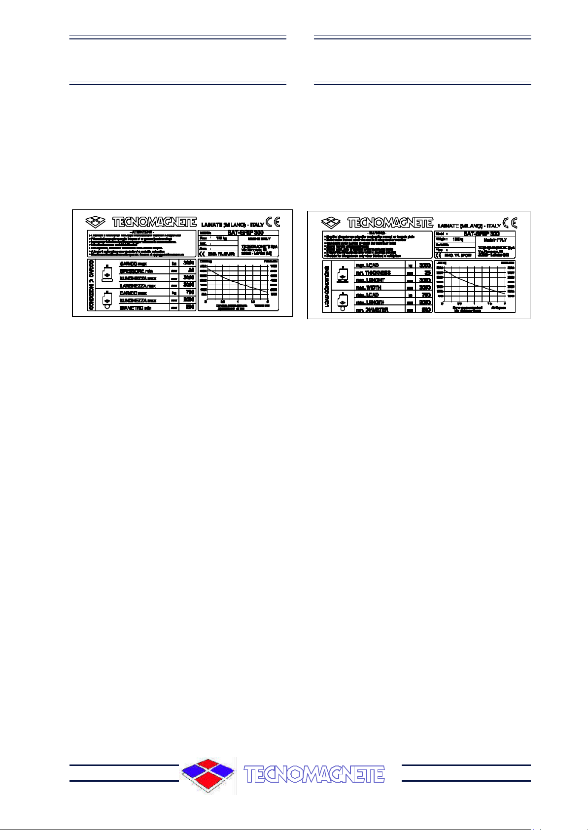
2.2 DATI DI TARGA
Sulla struttura portante dell’apparecchiatura è
applicata la targa di identificazione del
costruttoreediconformitàalleNORMECE
riportata di seguito.
ATTENZIONE
La targa non deve, per nessun motivo, essere
rimossa, anche se l’apparecchiatura venisse
rivenduta. Per qualsiasi comunicazione con il
costruttore citare sempre il numero di matri-
cola.
Sullastrutturavisonoinoltrealcunipittogrammi
indicanti avvertenze di sicurezza che devono
essere attentamente rispettate da chiunque si
appresti ad operare sulla stessa.
Il mancato rispetto di quanto prescritto, solle-
va la Ditta costruttrice da eventuali danni o in-
2.2 IDENTIFICATION DATA
The manufacturer’s identification and CE
RULING conformity plate is placed on the
supporting structure of the equipment. It is
also reported here below.
WARNING
The plate must not be removed at any time
even if the machine should be sold again.
Always refer to the serial number when
contacting the manufacturer.
Various safety drawings are placed on the
structure; the warnings conveyed must be
carefully observed by everyone dealing with
the equipment.
The company is not to be held responsible for
damage to property or accidents to people
which might occur if the above mentioned
Con questo si garantisce un margine
sufficienteda sovraccarichichesi generano
durante la movimentazione del carico,
sempre che vengano seguite correttamente
lenorme diimpiegodel sollevatore(posizio-
namento del carico ben centrato, carico non
superiore alla portata massima, eliminazione
dicorpiestranei,ecc.)
This ensures a sufficient safety margin against
overloading problems that may arise during
piece handling operations, as long as use
regulations of the lifting system are correctly
observed (e.g. placement of the load in a well
centered position, load non-exceeding the
maximum capacity, elimination of foreign
bodies, etc.)
USE AND MAINTENANCE
MANUAL
MANUALE USO E
MANUTENZIONE
MANUALE USO E
MANUTENZIONE USE AND MAINTENANCE
MANUAL
Page 11 of 27
®
2.3 CARATTERISTICHE
GENERALI
L’apparecchiaturadescrittanelpresentemanua-
le è un sollevatore magnetico
elettropermanente a batteria con
radiocomando.
Il sollevamento e la movimentazione di materiali
ferromagnetici eseguito attraverso l’uso di que-
sto tipo di sollevatore è reso possibile dalla ca-
pacitàdiquestimaterialidiconvogliarelelineedi
forza del campo magnetico prodotto dall’appa-
recchiatura. La tecnologia elettropermanente,
sviluppata da TECNOMAGNETE, consente di
sfruttare l’energia magnetica immagazzinata o
immagazzinabileinalcunelegheecompostipar-
ticolari: i magneti permanenti.
L’entrata in vigore delle nuove normative comu-
nitarie,siaperquantoriguardalasicurezzadegli
ambienti di lavoro sia per la compatibilità elettro-
magnetica(emissionicondotteeradiate),rende
ilcircuitoelettropermanentel’unicaalternativava-
lida nel campo dei sollevatori magnetici. Infatti,
questi sistemi:
2.3 GENERAL
CHARACTERISTICS
The equipment described in this manual is a
battery electropermanent magnetic lifting
device with radio control.
Lifting and handling operations of
ferromagnetic material, carried out with the
above mentioned equipment, are possible
thanks to the capacity of these materials to
convey the lines of force of the magnetic field
created by the system. TECNOMAGNETE’s
electro-permanent technology allows exploiting
magnetic power stored or storable in some
particular alloys or compounds: the permanent
magnets.
The new EC standards in force, relevant both
to the work environment safety and to the
electro-magnetic compatibility (conducted and
radiated emissions), regard the electro-
permanent circuit as the only valid alternative
in the field of the magnetic lifting systems. As
a matter of fact, these equipments:
- do not need any external source of energy
fortuni, a persone o cose che ne potrebbero
derivare e rende l’operatore stesso unico re-
sponsabile verso gli organi competenti.
warnings are not observed. In such a case,
the operator is the only person responsible.
MANUALE USO E
MANUTENZIONE
MANUALE USO E
MANUTENZIONE
Page 12 of 27 ®
USE AND MAINTENANCE
MANUAL
USE AND MAINTENANCE
MANUAL
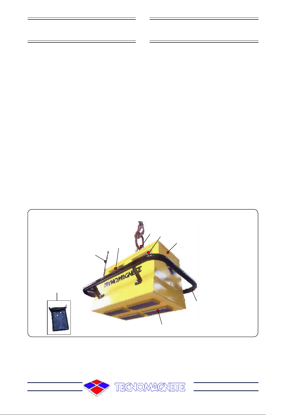
Î
Ê
Ë
Ï
Í
Ì
Ñ
1àAntenna radiocomando
2àBarra di manovra
3àSpina per ingresso alimentazione
4àPulsantiera frontale
5àTelecomando
6àCentralina elettronica
7àModulo magnetico
8àDAUTANAC
Ð
- non necessitano di una fonte continua esterna
di energia (a differenza delle apparecchiature
elettromagnetiche),
- hanno una sicurezza intrinseca essendo del
tutto autosufficienti per tutto il periodo di
movimentazione del carico,
-non influenzano l’operatività delle
apparecchiature circostanti (durante la fase di
rilascio del carico non vi è ritorno di energia nella
rete di alimentazione).
BAT-GRIP è dotato di serie di un carica batterie
incorporatoconrelativocavodicollegamentoalla
rete.
La ricarica può essere convenientemente effet-
tuata durante i fine settimana con tensione 220-
240 Vac. per un periodo di carica di circa 8 ore.
I cicli di attivazione/disattivazione sono inibiti in
casodiinsufficientecaricadellebatteriechevie-
ne segnalata da un indicatore luminoso
intermittente.
(unlike electro-magnetic equipments),
- are intrinsically safe because they are totally
self-sufficient during the entire load handling
stage,
-do not affect the surrounding machines
functioning (there’s no return of power in the
mains network during the load releasing stage).
BAT-GRIPissuppliedwithanincorporatedbattery
charger with a proper cable connecting to the
mains.
The recharge can be performed during the
weekendby means of220-240Vac for acharge
time of about 8 hours.
The enabling and disabling cycles can not be
performed in case of insufficient battery charge
signaled by an flickering indicator.
1àRadio control antenna
2àControl rod
3àSupply pin
4àFront push-button panel
5àRemote control
6àElectronic gearcase
7àMagnetic module
8àDAUTANAC

USE AND MAINTENANCE
MANUAL
MANUALE USO E
MANUTENZIONE
MANUALE USO E
MANUTENZIONE USE AND MAINTENANCE
MANUAL
Page 13 of 27
®
2.4CARATTERISTICHE
TECNICHE 2.4TECHNICAL FEATURES
MANUALE USO E
MANUTENZIONE
MANUALE USO E
MANUTENZIONE
Page 14 of 27 ®
USE AND MAINTENANCE
MANUAL
USE AND MAINTENANCE
MANUAL
3INSTALLAZIONE
3.1 VERIFICA DEL PRODOTTO
ACQUISTATO
Al ricevimento della fornitura, verificare che:
- gli imballaggi siano integri e non danneggiati;
- la fornitura corrisponda alle specifiche del-
l’ordine;
Se il tutto è integro, rimuovere l’imballo (salvo
nei casi di istruzioni differenti comunicate da
TECNOMAGNETE)everificarechel’apparec-
chiatura sia esente da danneggiamenti cau-
sati dal trasporto.
Verificare eventuali danni alla struttura e
schiacciamentiorotturedelleconnessionielet-
triche.
ATTENZIONE
Lacomunicazionedieventualidanneggiamenti
o anomalie deve pervenireentro dieci giornidal-
la data di ricevimento della fornitura.
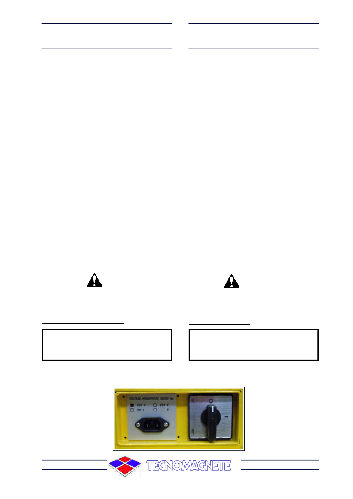
3.2 ALLACCIAMENTO
ELETTRICO
ATTENZIONE
L’allacciamento della macchina all' energia
elettrica deve essere effettuato da perso-
nale specializzato, solo durante le opera-
zioni di ricarica della batteria.
E’indispensabilechel’impiantodialimentazio-
ne elettrica del luogo dove si intende installare
l’impianto sia realizzato secondo le normative
vigenti.
Consultare gli schemi elettrici riportati alla
Sezione ALLEGATI.
3INSTALLATION
3.1 INSPECTION OF
PURCHASED PRODUCT
On receiving the equipment, check that:
- packings are unbroken and not damaged;
- the delivery corresponds to the order
specifications;
If a thorough check shows that all is well,
unpack the equipment (except when differently
indicated by TECNOMAGNETE) and make
sure the machine has not been damaged
during transport.
Check for possible damages on the structure
and for crushings or breakings of the electric
connections.
WARNING
In case of damages or anomalies, please call
the manufacturer ten days from receipt of the
goods.
3.2 ELECTRIC
CONNECTION
WARNING
The machine connection to the mains must
be carried out by specialised staff, only
during the battery recharge operations.
The electric system should be installed in
accordance with the laws in force.
Consult the electric diagrams in section
“ENCLOSURES”.

USE AND MAINTENANCE
MANUAL
MANUALE USO E
MANUTENZIONE
MANUALE USO E
MANUTENZIONE USE AND MAINTENANCE
MANUAL
Page 15 of 27
®
4PROTEZIONI E SICUREZZA
4.1 AVVERTENZE
Dato che il campo magnetico attraversa anche
corpi non magnetici (aria - pulviscolo - materiali
non ferrosi in genere), la massima efficienza di
un qualsiasi sollevatore magnetico si ottiene
quando i poli dello stesso sono a buon contatto
con la superficie del carico (Minore riluttanza).
La curva Forza-Traferro (V. figura), evidenzia
l’andamento della forza Fdi ancoraggio del sol-
levatore all’aumentare del traferro T (mm), cau-
sato da frapposizione di materiali amagnetici tra
i poli ed il carico (ad esempio calamina, corpi
estranei, concavità convessità, reggiature e le-
gacci, ecc.)
SI RACCOMANDA, pertanto, di evitare, per
quanto possibile, di appoggiare il sollevatore
inzone molto sporcheoaltamente deformate.
SIRACCOMANDA,sempreperquantopossibile,
dieliminarequalsiasimaterialeestraneodallasu-
perficie del carico prima di appoggiare il
sollevatore.
SI RACCOMANDA, di non sollevare cari-
chi con temperatura superiore a 80°C.
4PROTECTION DEVICES
AND SAFETY RULES
4.1 GENERAL INFORMATION
As the magnetic field goes through non-magnetic
material as well (air ,dust, non-ferrous material
in general), the magnetic lifting system will ope-
rate at full performances when its poles are well
in contact with the load surface (Minor
reluctance).
The Force-Gapcurve (see picture), marks the
retaining force (F) patternofthe lifting systemas
the gap (T) (mm) increases. This gap is caused
bynon-magnetic materialpresent betweenpoles
and load (e.g. calamine, foreign bodies,
concavities, convexities, slings, etc.)
Therefore, IT IS ADVISABLE to avoid, as
far as possible, placing the lifting system
in dirty or highly uneven areas of the load.
IT IS ADVISABLE , always as far as
possible, to remove any foreign body
present on the load surface before
positioning the lifting system.
IT IS ADVISABE not to lift load with a tem-
perature higher than 80°C.
T [mm]
MODULO MAGNETICO
MAGNETIC MODULE
LAMIERA
STEEL
Load Kg Force daN
Air gap mm
Curve on common steel
Min thickness 40 mm
MANUALE USO E
MANUTENZIONE
MANUALE USO E
MANUTENZIONE
Page 16 of 27 ®
USE AND MAINTENANCE
MANUAL
USE AND MAINTENANCE
MANUAL
4.2 NORME DI SICUREZZA
ßß Non sollevare il carico per nessuna ra-
gione se:
+Ilpesodelcaricoèsuperioreallaportata
massima riportata sulla targa del siste-
ma
+Ledimensionidelcaricoeccedonoquelle
previste
+Ilcaricopresentafortideformazioni,con-
cavità o convessità
+Latemperaturadelcaricoeccedequella
prevista
+Il sistema si presenta sbilanciato
+Se il ciclo di MAG non e finito oppure la
lampada rossa lampeggia
ßß Non movimentare il carico per nessu-
na ragione se:
+La lampada di segnalazione MAG non è
accesa
ßß Non eccitare con i moduli non in con-
tatto col carico
ßß In caso di accensione dell’indicatore del
livello minimo di carica della batteria,
sospendere le operazioni di solleva-
mento e procedere alla ricarica.
ßß Non muovere alcun selettore durante i
cicli di eccitazione o diseccitazione
ßß Non usare il sistema per spostare og-
getti
ßß Evitare urti inutili
ßß Non raffreddare mai in acqua il
sollevatore
ßß Non effettuare la ricarica delle batte-
rie con l’interruttore generale in pos.
ON al fine di non danneggiare i cir-
cuiti elettrici.
4.2 SAFETY RULES
ßß Never lift the load when:
+The load weight exceeds the maximum
capacity reported on the system
identification plate
+The load size is greater than the one
indicated in this manual
+The load is very uneven and irregular in
shape
+The load temperature is higher than the
one indicated in this manual
+The system is not well balanced
+The MAG stage has not been completed
or when the red lamp is flashing
ßß Never handle the load when:
+The MAG signal lamp is not on
ßß Do not energize when the models are
not in contact with the load
ßß In case the minimum battery charge
level indicator lights up, interrupt any
lifting operation, and recharge the
battery.
ßß Do not move any selector while
energizing/de-energizing
ßß Do not use the system to displace
objects
ßß Do not bump against the magnetic
heads and mecanical structures
ßß Never cool the magnetic heads in water
ßß Do not perform the battery recharge
when the main switch is in ON position,
to avoid any damage of the electric
circuits.
USE AND MAINTENANCE
MANUAL
MANUALE USO E
MANUTENZIONE
MANUALE USO E
MANUTENZIONE USE AND MAINTENANCE
MANUAL
Page 17 of 27
®
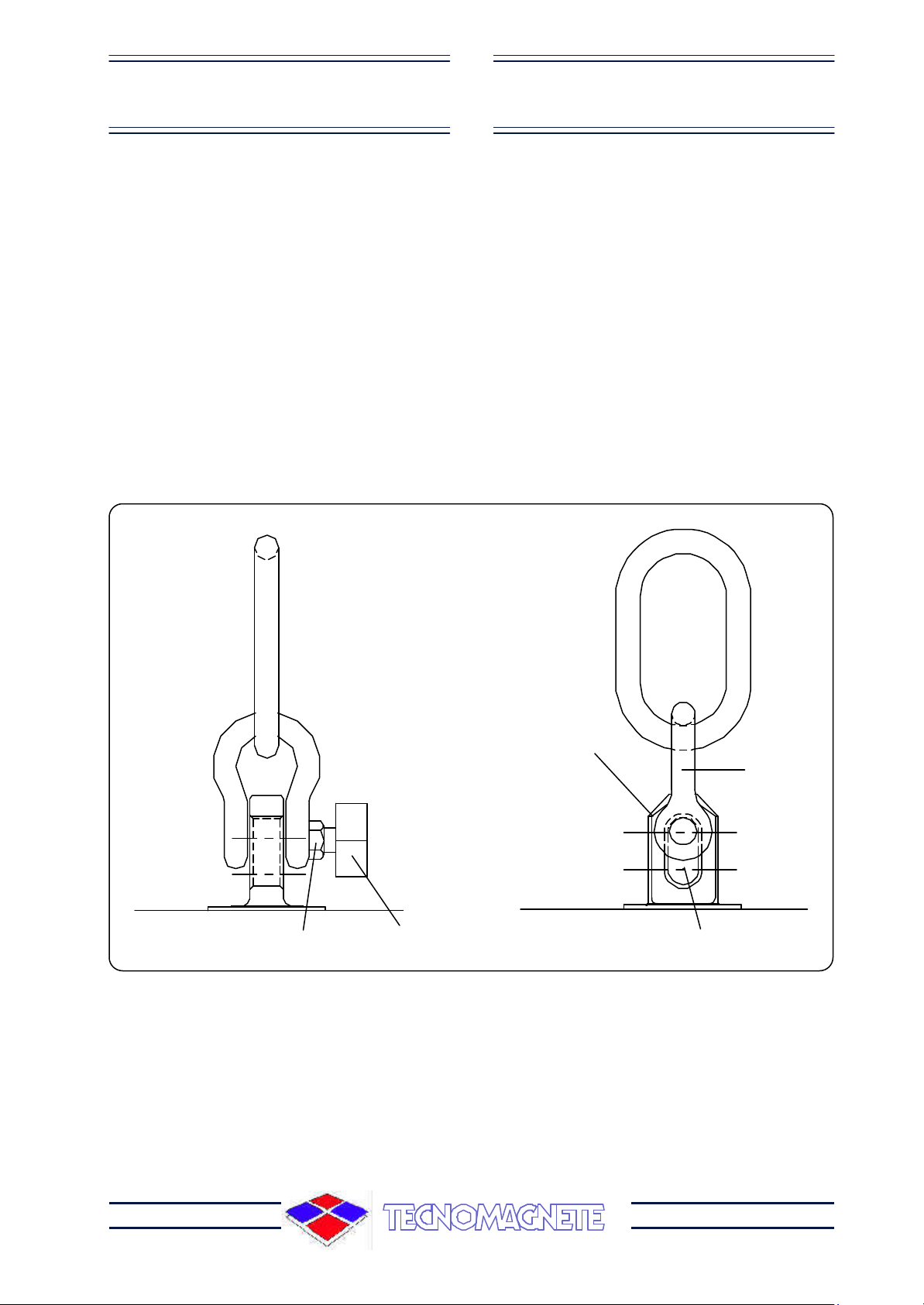
4.3 DISPOSITIVO DAUTANAC
Il DAUTANAC (Dispositivo AUTomatico
ANtidisattivazioneACcidentale),montatoin
prossimità dell’ orecchietta di aggancio,
blocca la disattivazione accidentale quan-
do l’anellone è in tiro.
Nellafiguradiseguitoriportatavieneillustra-
to il sistema di applicazione del dispositi-
vo.
Grillo
Shackle
4.3 DAUTANAC DEVICE
DAUTANAC (stands for “automatic device
against accidental de-activation”). It is
located near the chain eye-bolts and it
blocks any accidental de-activation of the
modules when the chain are tightened.
The picture below shows the application
system of this device.
Reed magnetico
Magnetic reed
Orecchietta con asola
Eye-bolt with slotted hole
Puleggia magnetica
Magnetic pulley
Vite di fissaggio
Fixing screw

MANUALE USO E
MANUTENZIONE
MANUALE USO E
MANUTENZIONE
Page 18 of 27 ®
USE AND MAINTENANCE
MANUAL
USE AND MAINTENANCE
MANUAL
5USO NORMALE
5.1 PULSANTIERE
1èPulsante di magnetizzazione (MAG)
2èLampada segnalazione di stato MAG
3èPulsante di smagnetizzazione (DEMAG)
4èLampada segnalazione di stato DEMAG
5èLampada indicatore carica massima batteria
6èLampada indicatore carica minima batteria
AèPulsante di magnetizzazione (MAG)
BèPulsante di smagnetizzazione (DEMAG)
5NORMAL USE
5.1 PUSH-BUTTON PANELS
PULSANTIERA AUSILIARIA
REMOTE CONTROL
Ê ÌË Í
Ï
Î
A
B
RADIOCOMANDO
RADIOCONTROL
1èMagnetization push button (MAG)
2èLamp signalling MAG status
3èDemagnetization push button (DEMAG)
4èLamp signalling DEMAG status
5èMax. battery charge indicator lamp
6èMin. battery charge indicator lamp
AèMagnetisation push button (MAG)
BèDemagnetization push button (DEMAG)
USE AND MAINTENANCE
MANUAL
MANUALE USO E
MANUTENZIONE
MANUALE USO E
MANUTENZIONE USE AND MAINTENANCE
MANUAL
Page 19 of 27
®
5.2 ISTRUZIONI PER
L’OPERATORE
1) Accendere il sistema agendo sull’interrut-
tore generale.
2) Posizionare il sollevatore sul carico facen-
do attenzione che la catena sia afflosciata
per disinibire il sistema di sicurezza
“DAUTANAC”.
3) Premere il pulsante MAG: a fine ciclo si
accende il LED verde corrispondente.
4) Sollevare il carico e verificare che la presa
sia ottimale.
5) Movimentare nella posizione voluta ed ab-
bassare il carico fino ad avere il tiro catena
in bando.
6) Premere il pulsante DEMAG: ad avvenuto
ciclosiaccendeilLEDrossocorrisponden-
te.
7) Per arrestare il sistema posizionare l’inter-
ruttore generale su ”0” e depositare il
sollevatore in luogo asciutto.
ATTENZIONE
CARICARE LE BATTERIE QUANDO VIENE
SEGNALATO L’ALLARME ATTRAVERSO IL
RELATIVO LED ROSSO LAMPEGGIANTE.
CARICA DELLA BATTERIA
Per caricare le batterie posizionare l’in-
terruttore su OFF e collegare il cavo di ali-
mentazione alla rete di distribuzione elettrica
220/240 V c.a.
Durante la carica si accende il corrispondente
LED verde che segnala l’operazione in corso.
5.2 OPERATING
INSTRUCTIONS
1) Turn on the system by acting on the main
switch.
2) Position the liftng device on the load paying
attention that the chain becomes flubby to
disable the “DAUTANAC” safety device.
3) Press the MAG push button: at the end of
the cycle the corresponding green LED
lights up.
4) Lift the load and check that the hold is good.
5) Handle in the desired position and move
downward the load until the chain tightening
is loosened.
6) Press DEMAG pushbutton;oncethecycle
is ended, the corresponding red LED lights
up.
7) To stop the system, position the main switch
on ”0” and put the lifting device in a dry area.
WARNING
CHARGE THE BATTERIES WHEN THE
BLINKING RED LED SIGNALS AN ALARM
.
BATTERY CHARGE
To charge the battery, position the switch
on OFF and connect the supply cable to the
220/240 Vac mains.
During the charge, the correspondig green LED
signalling that the operation is running, lights up.

MANUALE USO E
MANUTENZIONE
MANUALE USO E
MANUTENZIONE
Page 20 of 27 ®
USE AND MAINTENANCE
MANUAL
USE AND MAINTENANCE
MANUAL
6MANUTENZIONE
6.1 PREMESSA
Un’adeguata manutenzione costituisce fatto-
re determinante per una maggiore durata del
sistemaincondizionidifunzionamentoediren-
dimento ottimali e garantisce nel tempo la si-
curezza sotto il profilo funzionale.
ATTENZIONE
Far eseguire le operazioni di manutenzio-
ne SOLO ED ESCLUSIVAMENTE DA
PERSONALE ADDESTRATO.
6.2 NORME DI SICUREZZA
DURANTE LA
MANUTENZIONE
Le principali avvertenze da adottare in occa-
sione di interventi manutentivi sono:
+Mai toccare connessioniscoperte ecom-
ponenti senza prima aver scollegato l’ali-
mentazioneelettrica(l'interruttoredialimen-
tazione deve essere su “0”).
+Scollegare l’alimentazione elettrica pri-
madi rimuovere qualunque parte o effettua-
re qualsiasi sostituzione di componenti elet-
trici..
+Non indossare anelli, orologi, catenine,
braccialetti ecc. durante le operazioni di ma-
nutenzione.
+Utilizzare un tappetino di gomma isolante
(se possibile) sotto i piedi quando si effet-
tuano operazioni di manutenzione. Evitare
dioperaresupavimentibagnatioinambienti
molto umidi.
+Utilizzare sempre guantiprotettiviescar-
pe antinfortunistiche e ogni altro dispositivo
diprotezioneindividualenecessariononché
abiti che coprano il più possibile le parti del
corpo.
6MAINTENANCE
6.1 FOREWORD
An adequate maintenance lenghtens the
equipment life expectancy and keeps it in
excellent and efficient working conditions. It also
ensures lasting safety standards throughout
the years.
WARNING
It is highly recommended that ONLY
SKILLED PERSONNEL SHOULD
CARRY OUT MAINTENANCE
OPERATIONS.
6.2 SAFETY RULIES
DURING
MAINTENANCE
The main precautions to be adopted during
maintenance are:
+Never touch uncovered connections and
components without disconnecting the
equipment from the mains (general switch
on “0”).
+Disconnect the power supply before
removing any part or replacing any electric
component.
+Do not wear rings, watches, necklaces,
bracelets, etc. during maintenance
operations.
+Use , if possible, an insulating rubber carpet
under your feet when carrying out
maintenance operations. Refrain from
operating on wet floors or in very humid
environments.
+Always use protective gloves, safety
shoes and other personal protection
equipment which may be needed, as well
as clothes covering body parts as much as
possible.
Table of contents
Other TECNOMAGNETE Lifting System manuals


