AM-TC10626LA
Contents
Precautions...................................................................................................................................................1
1. General Information............................................................................................................................... 3
1.1.
Usage......................................................................................................................................................3
1.2.
Features...................................................................................................................................................3
1.3.
Specifications..........................................................................................................................................3
1.4.
Applicable Range...................................................................................................................................3
1.5.
Working Conditions ...............................................................................................................................3
1.6.
Description of Safety Signs................................................................................................................... 4
1.7.
Position of Safety Signs........................................................................................................................ 4
2. Main
Structure
.........................................................................................................................................5
3. Installation and adjusting.......................................................................................................................6
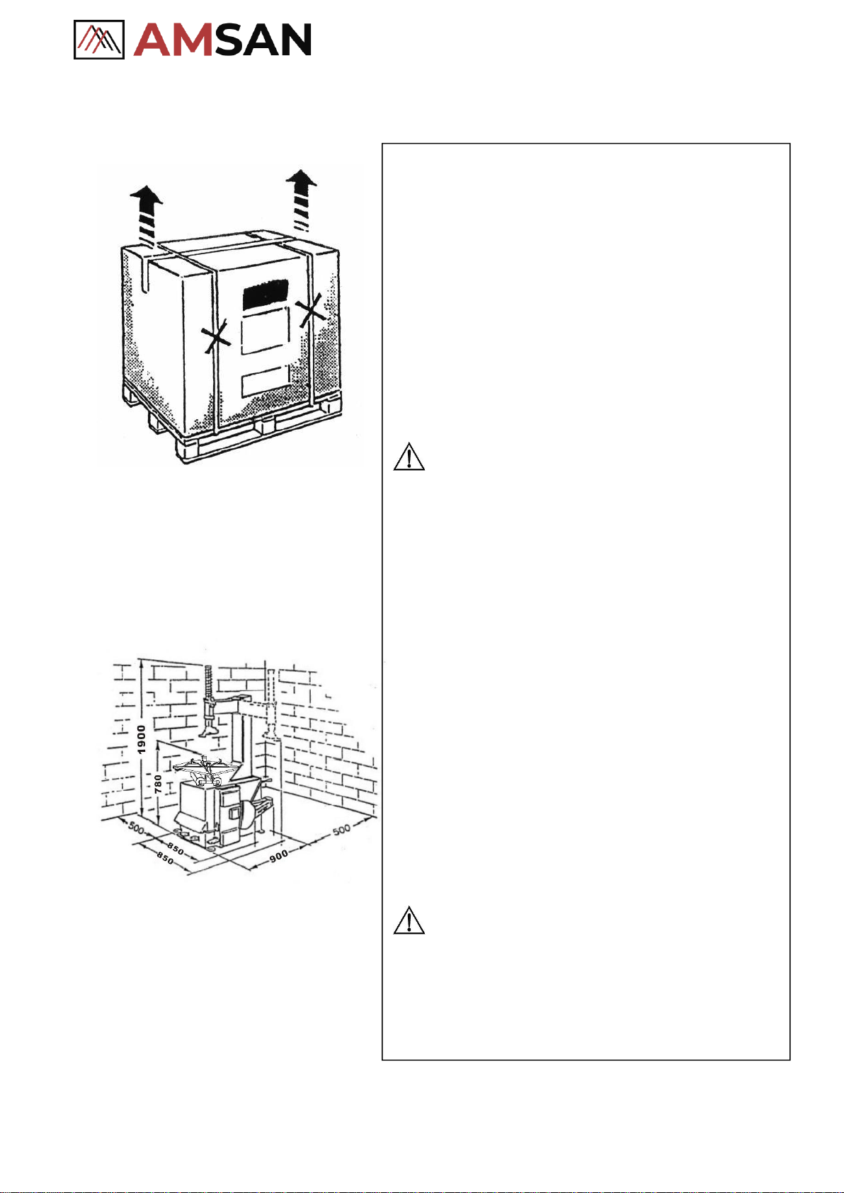
3.1.
Unpacking...............................................................................................................................................6
3.2.
Location..................................................................................................................................................6
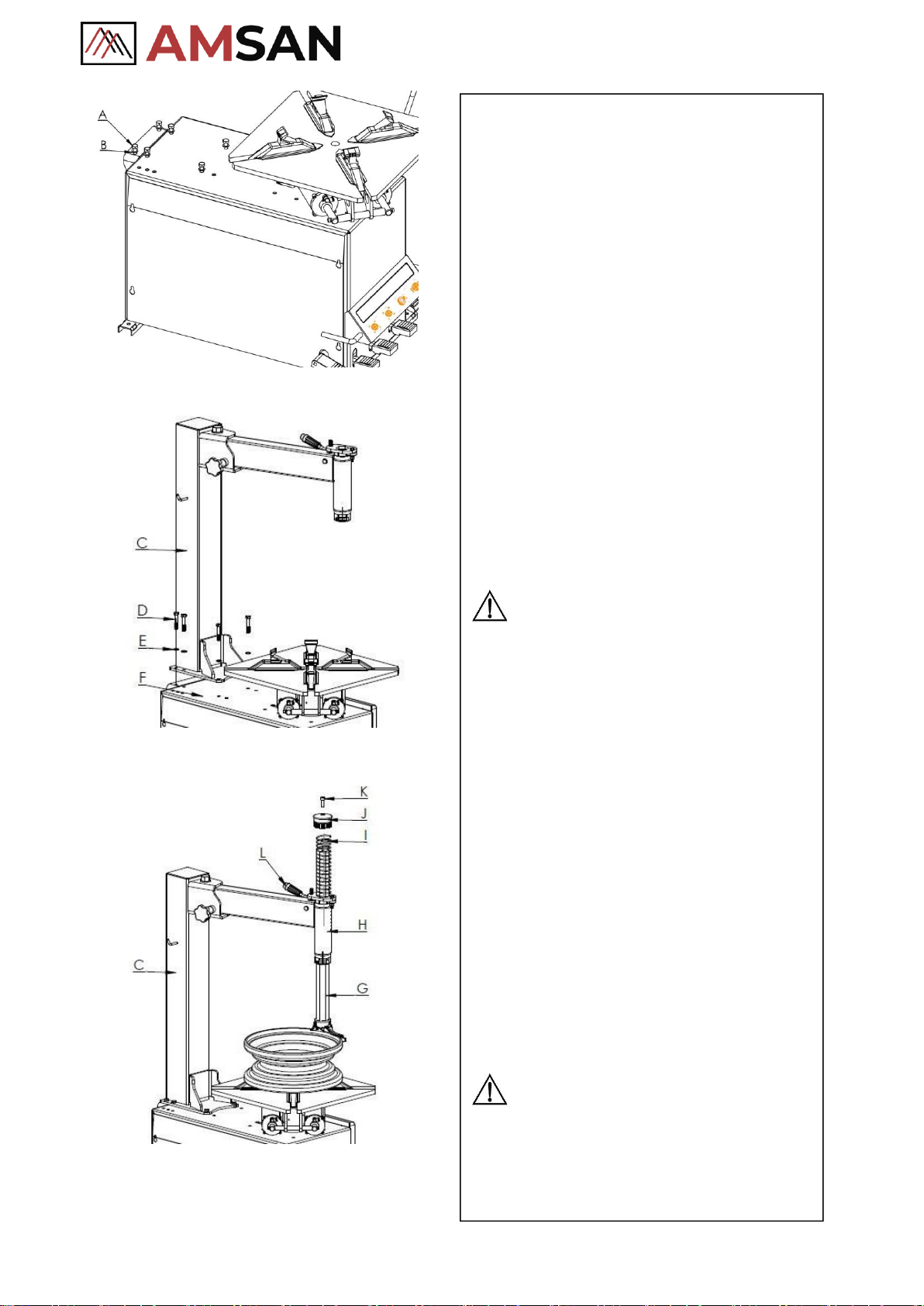
3.3.
Installation ..............................................................................................................................................7
3.4.
Power and Air Connections and Regulator.......................................................................................... 10
4. Operation...............................................................................................................................................11
4.1.
Principles..............................................................................................................................................11
4.2.
Demounting
Tire
..................................................................................................................................11
4.3.
Mounting Tire......................................................................................................................................14
4.4.
Inflating Tire......................................................................................................................................... 15
5. Trouble
Shooting
....................................................................................................................................15
6. Maintenance ..........................................................................................................................................
16
7. Storing and Scrapping..........................................................................................................................16
7.1.
Storing ..................................................................................................................................................16
7.2.
Scrapping..............................................................................................................................................16
8. Spare Parts List....................................................................................................................................
17
9. Exploded Drawings............................................................................................................................... 21
9.1.
Column Assembly................................................................................................................................
21
9.2.
Turntable Assembly..............................................................................................................................
22
9.3.
Gearbox & Motor Assembly ...............................................................................................................23
9.4.
Body Assembly ....................................................................................................................................24
9.5.
Bead Breaker Cylinder & Breaker Arm Assembly.............................................................................. 25
9.6.
Quick inflating system (optional)......................................................................................................... 26
9.7.
Simple left help arm (optional)........................................................................................................... 27
9.8. Simple double help arms(optional)....................................................................................................... 34
Appendix1:Electrical
Diagram
..............................................................................................................
40
Appendix 2:Air Passage Diagram .........................................................................................................41
Appendix 3:Optional accessories.........................................................................................................
41
Appendix 4:Maintenance Log ..............................................................................................................
42