Coats Rim Clamp 9024 User manual

1601 J. P. Hennessy Drive, LaVergne, TN USA 37086-3565 615/641-7533 800/688-6359 Manual Part No.: 8184377 02
HENNESSY INDUSTRIES INC. Manufacturer of AMMCO®, COATS®and BADA®Automotive Service Equipment and Tools. Revision: 01/07
9024
Rim Clamp®Tire
Changer
For servicing single piece
automotive and most light
truck tire/wheel assemblies
®
Installation Instructions
Operating Instructions
Safety Instructions
Maintenance Instructions
READ these instructions before placing unit in
service KEEP these and other materials delivered
with the unit in a binder near the machine for
ease of reference by supervisors and operators.
See
Operating
Instructions
on page 4.

ii • Important: Always read and follow the operating instructions.

Important: Always read and follow the operating instructions. • iii
Safety Instructions
Owner’s Responsibility
To maintain machine and user safety, the responsibil-
ity of the owner is to read and follow these instruc-
tions:
• Follow all installation instructions.
• Make sure installation conforms to all applicable
Local, State, and Federal Codes, Rules, and
Regulations; such as State and Federal OSHA
Regulations and Electrical Codes.
• Carefully check the unit for correct initial function.
• Read and follow the safety instructions. Keep them
readily available for machine operators.
• Make certain all operators are properly trained,
know how to safely and correctly operate the unit,
and are properly supervised.
• Allow unit operation only with all parts in place and
operating safely.
• Carefully inspect the unit on a regular basis and
perform all maintenance as required.
• Service and maintain the unit only with authorized
or approved replacement parts.
• Keep all instructions permanently with the unit and
all decals/labels/notices on the unit clean and visi-
ble.
• Do not override safety features.
Operator Protective Equipment
Personal protective equipment helps make tire serv-
icing safer. However, equipment does not take the
place of safe operating practices. Always wear durable
work clothing during tire service activity. Loose fitting
clothing should be avoided. Tight fitting leather gloves
are recommended to protect operator’s hands when
handling worn tires and wheels. Sturdy leather work
shoes with steel toes and oil resistant soles should be
used by tire service personnel to help prevent injury in
typical shop activities. Eye protection is essential dur-
ing tire service activity. Safety glasses with side
shields, goggles, or face shields are acceptable. Back
belts provide support during lifting activities and are
also helpful in providing operator protection.
Consideration should also be given to the use of hear-
ing protection if tire service activity is performed in an
enclosed area, or if noise levels are high.
Definitions of Hazard Levels
Identify the hazard levels used in this manual with the
following definitions and signal words:
DANGER
Watch for this symbol:
It Means: Immediate hazards, which will result in
severe personal injury or death.
WARNING
Watch for this symbol:
It Means: Hazards or unsafe practices, which could
result in severe personal injury or death.
CAUTION
Watch for this symbol:
It Means: Hazards or unsafe practices, which may
result in minor personal injury or product or property
damage.
Watch for this symbol! It means BE ALERT! Your
safety, or the safety of others, is involved!
DANGER
WARNING
CAUTION

iv • Important: Always read and follow the operating instructions.
Safety Notices and Decals
Failure to follow danger, warning, and cau-
tion instructions may lead to serious per-
sonal injury or death to operator or
bystander or damage to property. Do not
operate this machine until you read and
understand all the dangers, warnings and
cautions in this manual. For additional
copies of either, or further information, con-
tact:
Hennessy Industries, Inc.
1601 J.P. Hennessy Drive
LaVergne, TN 37086-3565
(615) 641-7533 or (800) 688-6359
www.ammcoats.com
For additional information contact:
Rubber Manufacturers Association
1400 K Street N. W.
Washington, DC 20005
(202) 682-4800
Tire Guides, Inc.
The Tire Information Center
1101-6 South Rogers Circle
Boca Raton, FL 33487-2795
(561) 997-9229
www.tireguides.com
Remember R.I.M.
Three Simple Steps To Help Keep Shops Safe
R.I.M. is a training program developed by Hennessy
Industries to help keep tire technicians safe. By follow-
ing the basic principles of R.I.M., technicians can avoid
situations that can cause catastrophic accidents like
tire explosions.
R.I.M. stands for read, inspect, and mount:
Read the tire size on a new tire before mounting to
make sure it is the proper size for the wheel.
Inspect the wheel for cracks, rust, and or other dam-
age that could cause an unsafe situation.
Mount the tire safely, making sure not to put any part
of your body over the tire during inflation.
The most serious of possible accidents is a tire explo-
sion. This is often caused by a tire/rim mismatch.
If a tire explodes on a tire changer, pressure causes it
to fly straight up at tremendous speed. If a technician
is standing over the tire, he can be seriously injured or
killed.
Hennessy’s R.I.M. program allows the technician to
avoid situations that can cause tire explosions and
other accidents. The full program, including training
videos, brochures, posters, and other materials, is
available from Coats distributors nationwide.
For more details, contact your Coats distributor or e-mail us.
WARNING
READ INSPECT MOUNT

Important: Always read and follow the operating instructions. • 1
Table of Contents
Safety Instructions . . . . . . . . . . . . . . . . . . . . .iii
Owner’s Responsibility . . . . . . . . . . . . . . . . . . . . . .iii
Operator Protective Equipment . . . . . . . . . . . . . . . .iii
Definitions of Hazard Levels . . . . . . . . . . . . . . . . . .iii
Safety Notices and Decals . . . . . . . . . . . . . . . . . . .iv
Remember R.I.M. . . . . . . . . . . . . . . . . . . . . . . . . . .iv
Principle Operating Parts . . . . . . . . . . . . . .2 - 3
Know Your Unit . . . . . . . . . . . . . . . . . . . . . . . . . . .2-3
Operating Instructions . . . . . . . . . . . . . . . .4 - 8
Bead Loosening and Demounting . . . . . . . . . . .4 - 7
Mounting . . . . . . . . . . . . . . . . . . . . . . . . . . . . . .7 - 8
Inflation . . . . . . . . . . . . . . . . . . . . . . . . . . .9 - 11
Bead Sealing . . . . . . . . . . . . . . . . . . . . . . . . . . . . .10
Bead Seating . . . . . . . . . . . . . . . . . . . . . . . . . . . . .10
Inflation . . . . . . . . . . . . . . . . . . . . . . . . . . . . . . . . .11
Stages of Inflation on a Conventional Tire
and Rim . . . . . . . . . . . . . . . . . . . . . . . . . . . . . .12
Mismatched Tires and Wheels . . . . . . . . . . .13
Performance, Custom, and Aluminum
Wheels . . . . . . . . . . . . . . . . . . . . . . . . . . .14 - 18
Performance Tires & Wheels • Demounting . .14 - 16
Performance Tires & Wheels • Mounting . . . .17 - 18
Custom and Special Wheels . . . . . . . . . . . . .18
Maintenance Instructions . . . . . . . . . . .19 - 21
Separator/Lubricator Maintenance . . . . . . . . . . . . .20
Mount/Demount Head Cleaning . . . . . . . . . . . . . .20
Pressure Limiter Maintenance . . . . . . . . . . . .20 - 21
Installation Instructions . . . . . . . . . . . . . . . . .21
Location . . . . . . . . . . . . . . . . . . . . . . . . . . . . . . . . .21
Air Source . . . . . . . . . . . . . . . . . . . . . . . . . . . . . . .21
Electrical Source . . . . . . . . . . . . . . . . . . . . . . . . . .21
NOTICE
Read entire manual before assembling,
installing, operating, or servicing this
equipment.

2 • Important: Always read and follow the operating instructions.
Principal Operating
Parts
Know Your Unit
Compare this illustration with the unit before placing
it into service. Maximum performance and safety will
be obtained only when all persons using the unit are
fully trained in its parts and operation. Each user should
learn the function and location, of all controls.
Prevent accidents and injuries by ensuring the unit is
properly installed, operated and maintained.
Do It Now!
Now is a good time
to fill out the Owner’s
Registry Card.
Tower — Support for horizontal and vertical
slides.
Air Inflation Gauge — Registers tire pressure
when clip-on chuck is attached to tire valve stem
and inflation pedal is released.
Release Valve — Allows the manual release of
air pressure from tire when clip-on chuck is
attached to tire valve.
Left Helpers and Support — Includes
mount/demount helpers, slide, cylinder, and valve
for operation.
Inflation Pedal — Three-position pedal that
allows inflation of tires through air hose and clip-
on chuck.
Bead Lifting Tool — Used to lift and position tire
bead correctly on duckhead®.
Clamps — Holds wheel to tabletop for tire
changing. Position outward to allow outside
clamping of wheels.
Right Helpers and Support — Includes
mount/demount roller and disk, slides, cylinder and
valve for operation.
✓

Important: Always read and follow the operating instructions. • 3
Slide Locking Valve — Locks and unlocks hori-
zontal/vertical slide and sets correct vertical/hori-
zontal position to maintain duckhead/wheel
clearance.
Slide Adjustment Handle — Adjusts horizon-
tal/vertical slide assembly for proper horizontal
and vertical positioning of duckhead®.
DuckHead®—Mounts and demounts tire from
wheel.
Bead Sealing Nozzles — Expands tire sidewall
to bead seat area of rim to seal tire to rim and
allow inflation.
Tower Tilt Pedal — Two-position pedal that
moves tower forward or back.
Clamp Control Pedal — Three-position pedal that
opens, holds, or closes rim clamps.
Bead Loosener Pedal — Controls operation of
bead loosener shoe.
Tabletop Pedal — Three-position pedal that con-
trols rotation of tabletop (forward, off, reverse).
Bead Loosener Shoe — Pivoting shoe for loos-
ening tire beads.
Lube Bucket — Dispenser for rubber lubricant.
Important Safety Decal — Important safety
information for the operator. DO NOT obstruct
with tire stickers or other materials.
Horizontal and Vertical Slides — Allows correct
positioning of duckhead®.

4 • Important: Always read and follow the operating instructions.
Operating Instructions
This unit must be properly operated and properly
maintained to help avoid accidents that could damage
the unit and injure the operator or bystanders. This sec-
tion of the Operating Instructions manual reviews
basic operations and use of controls. These instruc-
tions should be reviewed with all employees before
they are allowed to work with the machine. Keep these
instructions near the machine for easy reference.
Bead Loosening and Demounting
This machine may operate differently from
machines you have previously operated.
Practice with a regular steel wheel and tire
combination to familiarize yourself with the
machine’s operation and function.
A. Remember to remove all weights from both sides
of the wheel. Weights left on backside of wheel may
cause the wheel to be clamped unleveled. This may
result in the combination duckhead®contacting the rim
causing scratches. On alloy wheels, always rotate the
wheel one turn after setting the duckhead to insure
proper wheel chucking.
B. Always review with the owner any nicks and
scratches on expensive wheel and tire combinations
prior to servicing.
C. Review the performance wheel section of this
manual prior to servicing performance tire/wheel com-
binations.
Loosening the beads on a partially or fully
inflated tire is unsafe and causes excess
movement and friction against the bumper
pads and excessive wear on pivots. Deflate
the tire completely to prolong the life of
your machine.
1. Deflate the tire completely by removing the valve
core from the valve stem (figure 1). Be cautious and do
not smoke as a
flammable gas could have been intro-
duced into the tire at some time
.
Figure 1 - Remove Valve Core to Deflate Tire
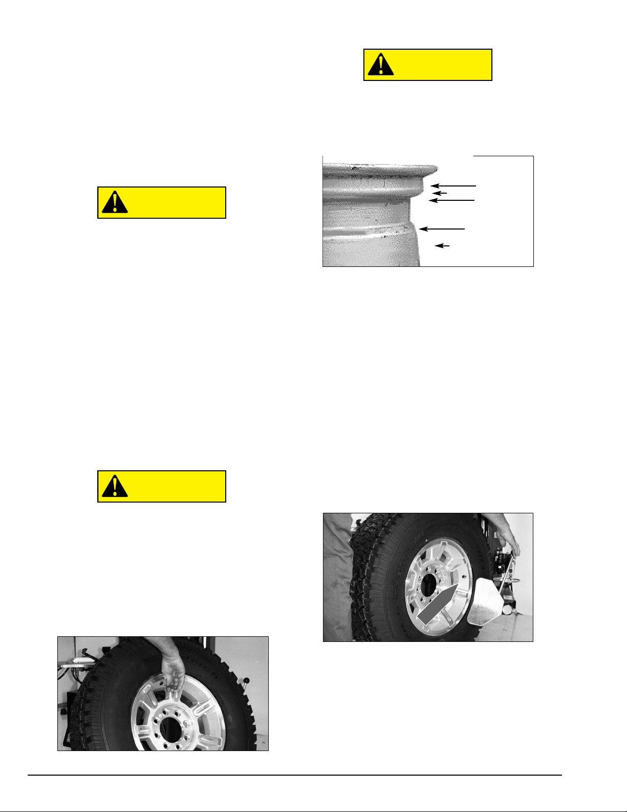
Tires are always installed and removed from
the rim’s narrow side.
D. Always loosen the bead on the narrow side of the
wheel’s drop center first. See figure 2 for more infor-
mation on the drop center.
Figure 2 - Determine Narrow Side of Wheel
E. The clamps on the tabletop may extend beyond the
tabletop itself. To avoid damaging the clamps, move
them to their full inward position before positioning a
tire for bead loosening.
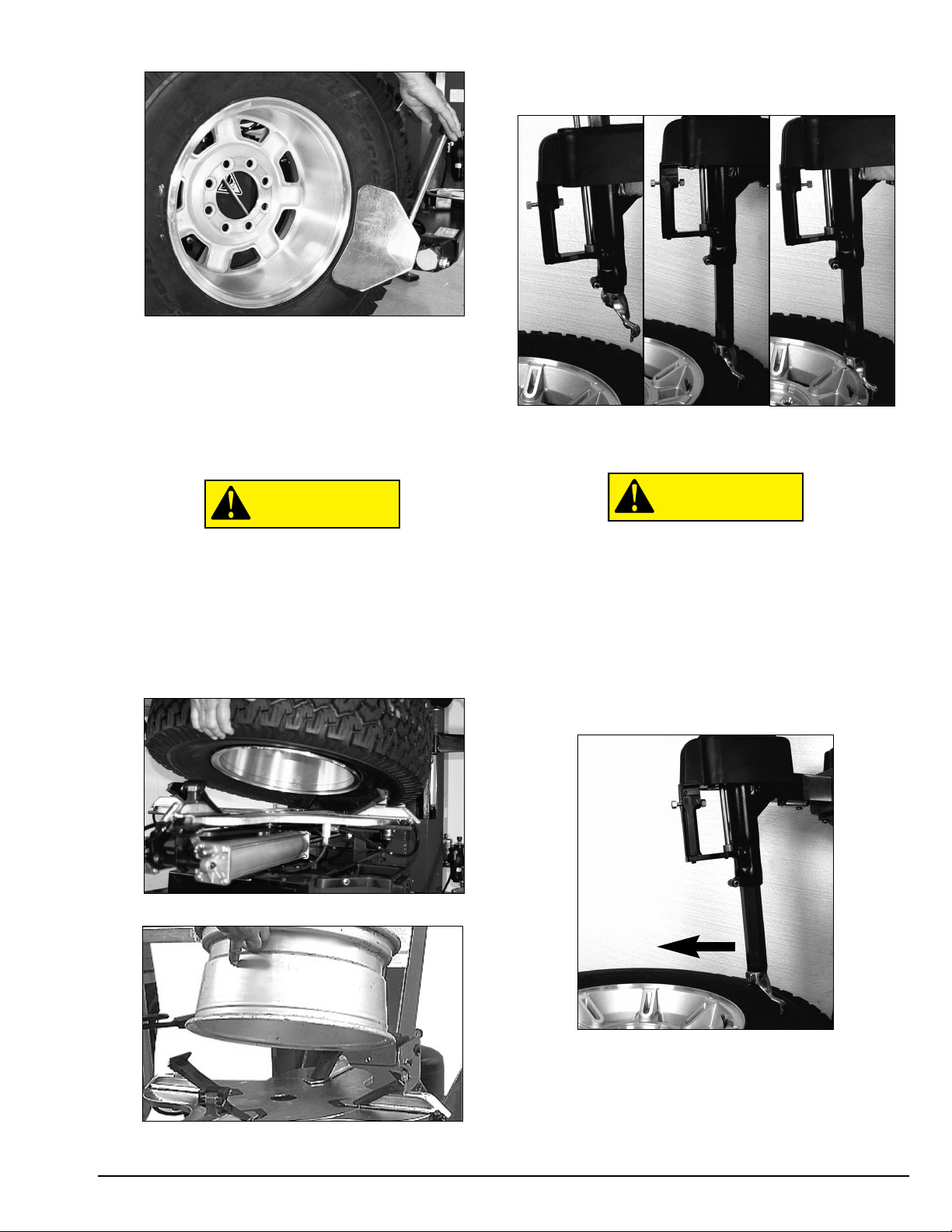
F. Use extra care in positioning the bead loosener
shoe on larger wheels/tires, and on alloy wheels. Make
sure the shoe rests next to but not on the rim, and not
on the tire sidewall.
2. Pull the bead loosener shoe away from the
machine and roll wheel into position. The valve stem
should be in the 2 o’clock position to accommodate a
possible asymmetric safety hump type rim. Position
the bead loosener shoe against the tire next to, but not
on, the rim. Press the loosener pedal to actuate the
shoe and loosen the bead. It may be necessary to
loosen the bead in multiple locations around the tire
(figure 3).
Figure 3 - Position Tire and Bead Loosener Shoe
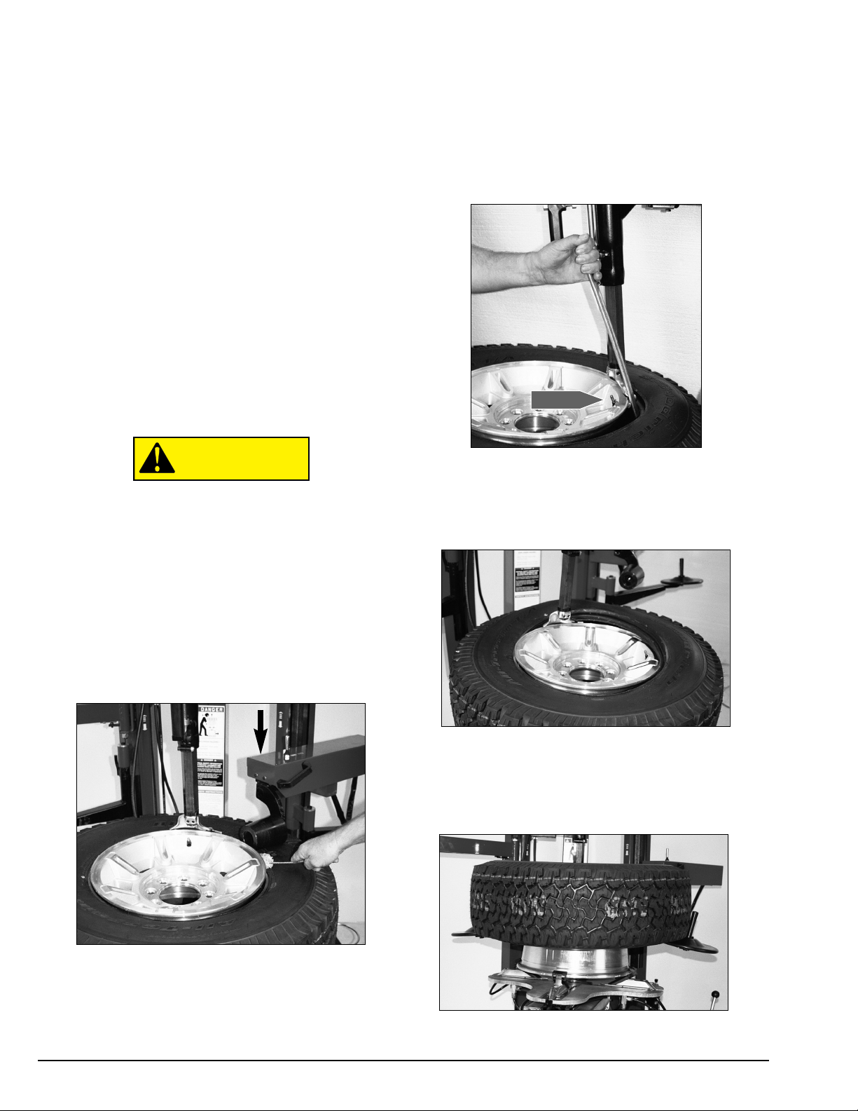
3. Turn the wheel around and repeat loosening pro-
cedure on the other side of the wheel (figure 4). Note
that the valve is placed at 2 o’clock for the initial loos-
ening procedure to accommodate a possible asym-
metric safety hump type rim.
CAUTION
CAUTION
CAUTION
Narrow Side
Long Side
Drop Center
Valve Stem

Important: Always read and follow the operating instructions. • 5
Figure 4 - Position Tire and Bead Loosener Shoe with Wheel
Turned Around
G. It will be easier to outside clamp the wheel to the
tabletop if the long side of the rim is loosened last.
4. Determine the mounting side of the wheel. The
mounting side is the narrow side of the drop center
(tire removed in figure 2 for clarity).
Avoid back injury, seek assistance when lift-
ing heavy tire/rim assemblies onto the tire
changer.
5. Place tire/wheel assembly on tabletop with
mounting side up (figure 5 & 6). Use the clamp control
pedal to move the clamps inward (push pedal down).
Use the clamp control pedal to move the clamps out-
ward (toggle pedal up).
Figure 5 - Clamp Outside on Mag Wheels
Figure 6 - Outside Clamped with Tire Removed
6. Take time to experiment with the duckhead®lock-
ing system (figure 7).
Figure 7 - With Valve Button as Shown,
Duckhead Retracks
Up,
Duckhead Descends Slowly, and
Duckhead Locks
into Position
Make sure the duckhead is in the retracted
position before moving the tower forward,
to prevent wheel damage.
7. Using the foot pedal, position the tower forward
(figure 8). See figure 7 for duckhead movement and
locking. With the tower forward, allow tool to descend
on the tire sidewall (figure 8). Then move the tool
toward the rim and actuate the locking button. As the
tool locks into place, the duckhead will move up and
back about 1/8-inch.
Figure 8 - Position Duckhead
8. The duckhead should not be in contact with the
rim edge after the duckhead is locked.
CAUTION
CAUTION

6 • Important: Always read and follow the operating instructions.
9. Check duckhead®positioning. Duckhead should
be positioned with 1/8 to 3/16-inch clearance between
the top of the rim edge and the bottom of the duck-
head, and 1/8 to 3/16-inch clearance between the top
of the rim edge and the duckhead roller. This clearance
will be maintained as long as the slide locking valve
remains locked. The operator may move the tower back
out of the way and back into place again without need-
ing to reposition the duckhead (when clamping a like
set of wheels).
H. The tool clearance may change with machine use
and should be inspected often. Failure to maintain the
proper clearance may result in damage to the wheel
rim and/or tire.
K. Normal tabletop rotation for demounting is clock-
wise. Depress the tabletop pedal to rotate this direc-
tion. To rotate the tabletop counterclockwise, lift the
pedal up with your toe.
L. Tabletop rotation can be stopped at any time by
removing your foot from the rotation pedal.
At times during the mounting and
demounting procedure, the bead lifting tool
may encounter resistance and can be
thrown. Keep one hand firmly on the tool to
avoid possible tool disconnect. Use the
reversing feature to back out of jam-ups. A
thrown tool can cause injury.
10. Apply tire manufacturer’s approved rubber lubri-
cant liberally to entire circumference of both beads
after loosening and placing on tabletop. Using R.H.
helper to hold down top bead while rotating wheel will
make lubrication easier (figure 9).
Figure 9 - Apply Rubber Lubricant to the Beads
11. Insert smooth curved end of the bead lifting tool
over the clockwise end of duckhead and below the
upper bead of the tire. Lift the bead up and over the
knob on the duckhead (figure 10). Also, note the valve
stem position to the duckhead, this position reduces
stresses in the bead and allows an easier bead lift.
Push down on the tire opposite the duckhead to allow
the bead utilize the drop center area of the rim.
Figure 10 - Insert Bead Lifting Tool
12. Depress the tabletop pedal to rotate the wheel.
The duckhead will guide the tire bead up and over the
edge of the wheel (figure 11). Continue rotation until
the upper bead is demounted.
Figure 11 - Demount Upper Bead
13. For lower bead removal lift the tire (figure 12)
and insert the lift tool same as on upper bead (figure
13). On large or heavy tires, the helper arms may be
used to lift the tire.
Figure 12 - Lift the Tire for Lower Bead Removal
CAUTION
Valve Stem

Important: Always read and follow the operating instructions. • 7
Figure 13 - Insert Bead Lifting Tool
14. With the tire in position (note that the valve
stem is under the duckhead), rotate the lever down to
position the bead on top of the duckhead. Depress the
foot pedal to rotate the tire. The duckhead will guide
the lower tire bead off of the rim.
M. With tube-type tires, demount the upper bead and
remove the tube before demounting the lower bead.
After successfully completing the demount process,
proceed to MOUNTING.
Mounting
This information must be read and followed carefully
to prevent accidents and injuries during mounting.
Attempts to force a bead seat on mis-
matched tires and wheels can cause the tire
to violently explode, causing serious per-
sonal injury or death to operator and/or
bystanders.
Check tire and wheel carefully before
mounting. Make sure the tire bead diameter
and wheel diameter match exactly. Consult
the Tire Guide and/or Rubber
Manufacturer's Association for approved
rim widths for tire sizes.
Never mount a damaged tire. Never mount
a tire on a rusty or damaged wheel.
Damaged tires and/or wheels may explode.
When in doubt do not mount.
Never mount a tire and wheel handed to
you by anyone without checking both tire
and wheel for damage and to be certain the
sizes match. Do not let untrained persons
operate tire changer and keep bystanders
out of service area.
Forcing the tire onto the rim can cause bead
damage. If you damage the tire bead during
mounting, STOP!, remove the tire and mark
it as damaged. Do not mount a damaged
tire.
1. Before any mounting, inspect the tire for damage
and verify size match between tire and wheel (fig. 14).
Figure 14 - Verify Size Match Between Tire and Wheel
2. Inspect the wheel closely for damage. Clean the
wheel and remove any light corrosion or rubber residue
(figure 15). Do not attempt to service a heavily cor-
roded wheel, damaged wheel, or bent wheel.
Figure 15 - Inspect and Clean the Wheel
CAUTION
CAUTION
CAUTION
WARNING
WARNING
DANGER
Valve Stem

8 • Important: Always read and follow the operating instructions.
3. Inspect the valve stem and replace if necessary.
Next lubricate the tire beads liberally with tire manu-
facturer’s approved rubber lubricant (figure 16).
Figure 16 - Lubricate Tire Beads Liberally
4. Place tire over wheel and move tower arm into
position. Position tire so that the lower bead is above
the rear extension of the duckhead®and below the
front knob (figure 17).
Figure 17 - Position Tire Against Duckhead
5. Depress tabletop pedal and rotate the wheel to
mount the lower bead. Use the drop center of the
wheel by forcing down on the tire just ahead of the
mounting tool and follow as the tire rotates (figure 18).
Rotate the tabletop until the lower bead is mounted.
Figure 18 - Mounting Lower Bead
6. For top bead installation, rotate the tabletop until
the valve stem on the wheel is 90 degrees ahead of
the duckhead (at the 3 o’clock position). Lift the upper
bead of the tire up and over the rear of the duckhead.
With your hand or using the power roller, press down
on the tire sidewall between the duckhead and the
valve stem to hold the tire in the rim drop center. The
bead should also be under the right side of the knob on
the duckhead (figure 19). Depress the tabletop pedal
and rotate the tire until the bead is mounted. Be care-
ful to assure the bead stays in the rim drop center in
the area ahead of the duckhead.
Figure 19 - Mounting Top Bead
P. If tabletop rotation stalls, reverse the tabletop
momentarily until the tire bead is again loose on the
wheel. Reposition the tire on the duckhead, make sure
the bead is correctly positioned in the drop center of
the wheel; then attempt mounting again.
R. For tube type tires, mount the lower bead first,
move the tower back, install the tube, and then mount
the upper bead.
90º

Important: Always read and follow the operating instructions. • 9
Inflation
Tire inflation is performed in three steps: BEAD
SEAL, BEAD SEAT, and INFLATION. These steps are
explained in detail on page 12. Read the explanation of
each step and understand them thoroughly before pro-
ceeding.
Tire failure under pressure is hazardous.
This tire changer Will Not Restrain
Exploding Tires, rims or other related equip-
ment. Inspect tire and wheel carefully for
match, wear, damage, or defects before
mounting. Always use approved tire bead
lubricant during mounting and inflation.
The clip-on chuck allows the operator to
keep hands and entire body back from
inflating tire. The chuck must be an
open/freeflow style with all parts in proper
working order.
Check for proper inflation gauge operation.
Accurate pressure readings are important to
safe tire inflation. Refer to the Operating
Maintenance section of this manual for
instructions.
The inflation pedal, located at the center of the left
side of the machine, controls the flow of air through
the inflation hose, and has three positions.
Note:The clip-on chuck on the end of the hose should
always be an open/freeflow style with all parts in
proper working order.
Position 1 - Tire Pressure – With the inflation hose
attached to the tire valve and the pedal in this position,
the air gauge will register the air pressure in the tire.
Whenever your foot is removed from the pedal, it will
return to this position.
Position 2 - Tire Inflation – This is the first activated
position. With the inflation hose attached to the tire
valve and the pedal in this position, line pressure is
allowed to flow through the valve system and into the
tire for inflation. Correct tire pressure is not indicated
on the gauge in this position.
Position 3 - Bead Sealing – This is the second and
last activated position. With the inflation hose attached
to the tire valve and the pedal in this position, line pres-
sure is allowed to flow through the valve and to the air-
flate bead seal jets on the tabletop for bead sealing.
1. If the rim has been clamped from the outside for
tire mounting, release the clamps, lift the tire, and
move the clamps to the center of the tabletop.
The inflation pedal, located at the center of the left
side of the machine, controls the flow of air through
the inflation hose.
Note the Pedal Positions (See Diagram)
Use of bead sealing jets without a tire in
place can cause dirt and debris to be blown
into the air with enough force to injure
operator and/or bystander. Do not use the
bead sealing control position to inflate a
tire.
R. This unit is equipped with a pressure limiter to
assist the operator with proper tire inflation. When the
inflation pedal is held in position 2, the pressure limiter
cycles the machine between position 2 (inflation) and
position 1 (at rest, no airflow to tire). This cycling helps
to prevent over inflation of the tire. Tires can still be
over inflated and explode with the use of this pressure
limiter if all of the instructions in this manual are not fol-
lowed completely. The pressure limiter will keep most
car and light truck tires from inflating beyond 60 PSI
(smaller tires may reach higher pressures). It is the
operator's responsibility to follow all instructions and to
control inflation pressure as specified in these instruc-
tions. Check the function of the pressure limiter regu-
larly and maintain it according to the instructions
provided in this manual for safe and proper operation.
Do not tamper with or attempt to adjust the pressure
limiter. Tires requiring inflation beyond 60 PSI should
be inflated in a safety cage.
CAUTION
CAUTION
CAUTION
DANGER
Tire
Inflation
Inflation Pedal Positions
Bead
Sealing
Tire
Pressure

10 • Important: Always read and follow the operating instructions.
Bead Sealing
1. Position valve stem in front of operator and con-
nect the inflation hose with the clip-on chuck. Hold tire
up against upper edge of the wheel. Be sure tire’s top
bead does not cover the bottom of the valve stem (fig-
ure 20).
Figure 20 - Lift Tire Upwards for Bead Sealing
2. Depress inflation pedal to position 2 and hold
about one second to begin air flow through tire valve,
then depress pedal to position 3 and hold briefly —
less than one full second. The blast of air from the jets
will expand tire and seal the beads.
3. Release the inflation pedal and allow it to return to
position 1. Verify that both beads are completely sealed
to the wheel. Repeat these steps if beads have not
sealed. It may be necessary to wait a few seconds for
the air storage tank pressure to recover before
attempting again.
S. If tire and wheel are properly lubricated and opera-
tor cannot achieve bead seal after three or four
attempts, the valve core may be removed from the
valve stem to allow more air flow into the tire to assist
with bead seal. After bead seal is achieved, remove the
clip-on chuck and reinstall the valve core. Reattach the
clip-on chuck after core is installed.
Bead Seating
NEVER exceed 40 PSI to seat beads while
using this tire changer. If more than 40 PSI is
permitted by tire manufacturer, ALWAYS use
safety cage and clip-on chuck. NEVER
exceed recommended pressure after seat-
ing beads. ALWAYS keep hands and entire
body back from inflating tire.
An exploding tire, wheel, or bead sealing
equipment may propel upward and out-
ward with sufficient force to cause serious
injury or death to operator or bystander.
Check tire pressure frequently. If operator is
unable to obtain Bead Seat, something is
wrong. Deflate tire completely, inspect tire
and wheel, correct any problems found,
relubricate both tire beads, and reattempt
Bead Seal and Seat procedures. Follow all
safety instructions in this manual and on
machine.
1. Once tire pressure is indicated on the air gauge
(inflation pedal in position 1; foot removed from pedal),
continue to inject air into the tire (inflation pedal posi-
tion 2) in short intervals. Check the pressure fre-
quently. Stand back during bead seat. Keep hands,
arms, and entire body away from tire during this pro-
cedure (figure 21).
Figure 21 - Stand Back during Bead Seat
WARNING
DANGER

Important: Always read and follow the operating instructions. • 11
Inflation
NEVER exceed tire manufacturer's recom-
mended air pressure. Tires can explode,
especially if inflated beyond these limits.
Use clip-on air chuck, keep hands, arms and
entire body back from inflating tire. Avoid
distraction during inflation. Check tire pres-
sure frequently to avoid over inflation.
Excessive pressure can cause tires to
explode, causing serious injury or death to
operator or bystander.
1. Make sure both beads are seated. When both
beads are seated, the tire is ready for inflation.
2. Replace the valve core if it was removed.
3. Depress the inflation pedal to position 2 to inflate
the tire. The pressure limiter will cycle the air flow as
described earlier. On most tires, the pressure limiter
will cease air flow at approximately 60 PSI. On smaller
volume tires the pressure may be higher.
4. Release air pressure from tire by pressing the
manual release valve button (inflation hose must be
attached to the valve stem, Figure 22). Never add or
adjust tire pressure using an air hose without a clip-on
air chuck and in-line valve. Do not use a hand-held style
chuck (figure 23).
5. Important: When inflating tires that require more
than 60 PSI, always use a safety cage and air hose with
a clip-on air chuck and in-line valve. The air hose must
have enough length between the chuck and the opera-
tion/in-line valve to allow the operator to stand outside
the trajectory.
Figure 22 - Location of Manual Release Valve
Figure 23 - Do Not Use a Hand-held Style Air Chuck
WARNING
Explosion Hazard
Never inflate tire
above
manufacturer's
recommended
pressure after bead
is seated.
DANGER
Explosion Hazard
Never exceed 40
PSI while seating
beads.
Remember R.I.M.
(see page iv and back cover)
DANGER

12 • Important: Always read and follow the operating instructions.
Stages of Inflation on a
Conventional Tire and Rim
Review these descriptions and diagrams carefully. Refer to them as
necessary during bead sealing, bead seating, and inflation to verify
that you are proceeding properly and safely.
Bead Sealing
Bead sealing is the process of capturing air pressure between the
tire and the rim. The tire will usually contain about 1/2 to 2 PSI at ini-
tial bead seal
Bead Seating
Bead seating usually occurs on the long tapered side of the wheel
first and the shorter side last. Bead seating will usually require at
least 7 PSI in the tire. 40 PSI is the maximum safe pressure at this
stage regardless of tire operating pressure.
Most European import cars and many aftermarket alloy wheels are
very tight and can be difficult to bead seat. Also note that asymmet-
rical hump and run-flat tires are extremely difficult to bead seat.
Follow tire manufacturer’s recommended procedure for bead seating.
Inflation
After the beads are seated, the tire is ready to be inflated. Do not
inflate the tire above the manufacturer’s recommended pressure as
stamped on the tire sidewall. The typical inflation pressure for auto-
mobile tires is between 24 and 45 PSI. Light truck inflation pressure
typically covers a wider range.
Air flow through valve requires about
140 PSI air pressure drop to ensure
sufficient flow on difficult tires.
Usually last to “pop” is the mount side.
Requires visual
conformation of
bead seat.
Stand clear of the tire during bead seat and inflation.
Stand clear of the tire during inflation.
Requires rubber lubri-
cant on both upper
and lower beads. Make sure the tire bead is
not obstructing air flow
from the valve stem
into the inside of
the tire.

Important: Always read and follow the operating instructions. • 13
Mismatched Tires and Wheels
Never attempt to mount and inflate mis-matched tires
and wheels.
Mismatched tire and wheel combinations can explode,
causing personal injury or death to operator and/or
bystanders.
DANGER
Even Size Tires
14.0,15.0,16.0,17.0, etc.
Half Size Tires
14.5, 15.5, 16.5, 17.5, etc.
Even Size Wheels
14.0, 15.0, 16.0, 17.0, etc.
15°
5°
Note the gap in sealing area
Note 15° bead seat
Bead may seal; but it
will not seat properly
Half Size Wheels
14.5, 15.5, 16.5, 17.5, etc.

14 • Important: Always read and follow the operating instructions.
Performance, Custom,
and Aluminum Wheels
To avoid personal injury or damage to com-
ponents only tire technicians with experi-
ence and training on custom wheels should
attempt to service expensive custom alloy
or aluminum wheels, high-performance
low-profile tires and EMT/run-flat tires.
Many tires/wheels have pressure sensor
devices that are manufactured by different
companies, there are no standards on type
or mounting; therefore, follow the instruc-
tions that apply to the sensor being serv-
iced. For further information on these
devices, contact the individual sensor man-
ufacturer.
Pre-Operation Notes:
• Ensure all weights have been removed.
• Assistance will be required on wide wheels.
• Clamp wheel from the outside.
• Use ample lubricant for mounting and demounting
• Always review wheel nicks and/or scratches with
the owner before servicing.
Performance Tires & Wheels • Demounting
Follow these instructions for performance type tires
and wheels, including run-flat tires and their associated
wheels, and asymmetrical hump wheels.
1. Remove the valve core and completely deflate the
tire. On many performance wheels a valve type sensor
may be inside of the rim. These devices are expensive
and should be serviced with care. After deflating the
tire, loosen and remove the retaining nut and then tap
lightly with a hammer to allow the valve sensor to fall
inside the tire before further service work (figure 24).
Figure 24 - Rim with a Valve Type Sensor (Tire Removed for
Clarity)
2. Some wheels have a low-pressure sensor/trans-
mitter strapped to the wheel. This is especially true on
run-flat tire/wheel systems. To avoid damaging the sen-
sor, always loosen the top bead with the valve stem at
the 2 o’clock position first, to determine sensor loca-
tion. Then loosen the bottom bead and the remaining
circumference of the beads as necessary at a location
that will not damage the sensor. (Figure 25).
Figure 25 - Wheel with Strapped on Low Pressure
Sensor/Transmitter
3. Wheels with an asymmetrical hump have a larger
"ledge" type hump around the wheel except at the
valve hole making them more difficult to mount and
demount loosen bead (Figure 26).
Figure 26 - Asymmetrical Hump Wheel
4. Pull the bead loosener shoe away from the
machine and roll the tire in position with the valve stem
in the 2 o’clock position (above the bead loosener
shoe). Always loosen the bead on the narrow/mount-
ing side of the wheel first (figures 2 and 27).
Figure 27 - Position Tire for Bead Loosening
CAUTION
CAUTION
Smooth
Hump At
Valve Hole
Ledge
Hump Rest
of Wheel
Valve Stem
Sensor
Valve Stem

5. Loosen bottom bead, starting with valve stem
positioned at the 2 o’clock position above the bead
loosener shoe (figure 28).
Figure 28 - Loosen Bottom Bead
6. Liberally lubricate the bottom bead of the tire (fig-
ure 29).
Figure 29 - Lubricate Bottom Bead
7. After loosening and lubricating the lower bead,
rotate the tabletop until the clamps are in the 12, 3, 6,
and 9 o'clock positions (Figure 30).
Figure 30 - Rotate Tabletop to 12 O’clock
Avoid back injury, seek assistance when lift-
ing heavy tire/rim assemblies onto the tire
changer.
8. Clamp wheel from the outside. Position rim edge
into clamp at 12 o'clock position. Lower the wheel and
depress the clamp control pedal. Slowly move the
clamps inward until they securely contact the outside
edge of the rim (Figure 31).
Figure 31A - Clamp Wheel (Tire Removed for Clarity)
Figure 31B - Outside Clamped with Tire Removed
Tip: This is usually accomplished by crouching down in
front of the tire changer, holding the wheel with the
right hand, and operating the clamp control pedal with
the left hand. This allows the operator to watch the
clamps as they move inward to ensure proper, damage-
free clamping.
9. After clamping the tire and wheel, position the
duckhead®as explained in the previous section.
10. Lubricate upper bead liberally. Use the R.H.
tapered roller to help push the tire bead down so bead
area is easier to reach for lubrication (figure 32).
Figure 32 - Lubricate Upper Bead
CAUTION
Important: Always read and follow the operating instructions. • 15
Valve Stem

16 • Important: Always read and follow the operating instructions.
11. After bead lubrication, position the tire and
wheel for demounting by locating the valve hole or
stem in front of the duckhead®(figure 33).
12. Next, position the L.H. helper opposite the duck-
head and apply a force to the tire that will allow the
bead to slide into the drop center of the rim as the
bead is lifted onto the duckhead (figure 33).
Figure 33 - Position Tire/Wheel for Demounting
13. Next, insert the lift tool into the tire, rim inter-
section, raise the (R.H. helper) taper roller from the tire
sidewall and lift the bead carefully onto the right side of
the duckhead (figure 34).
Figure 34 - Lift Bead Carefully onto Duckhead
14. Next, raise the (R.H. helper) from the tire side-
wall and move to the stored position. Next, jog the
machine rotation to start the upper bead removal (fig-
ure 35), continue rotation until the upper bead is com-
pletely removed from the rim.
Figure 35 - Start Upper Bead Removal
15. Once the upper bead is removed, review the
wheel for strap-on type sensors. Position the plastic
disks under the lower sidewalls and raise the lower
sidewall of the tire to the top of the drop center of the
rim (figure 36).
Figure 36 - Raise Lower Bead to Top of Drop Center of the
Wheel
16. With the tire in the up position, insert the lift bar
and raise the lower bead onto the duckhead (figure 37).
17. Lower the lift disk on each side and move them
away from the tire (figure 37).
18. Depress the rotation pedal and dismount the
lower tire bead from the rim (figure 37).
Figure 37 - Dismount the Lower Tire Bead from the Rim
Table of contents
Other Coats Tyre Changer manuals
Popular Tyre Changer manuals by other brands

ATH-Heinl
ATH-Heinl M72Z Plus operating instructions

Hofmann
Hofmann Monty 1270 Smart Operation manual

Rotary
Rotary R247D.CL Operation and maintenance manual

TSI Instruments
TSI Instruments STE-M OPERATION & TROUBLESHOOTING

John Bean
John Bean T 8026 Operator's manual

SMART-Workshop
SMART-Workshop TIRE TRUER operating manual