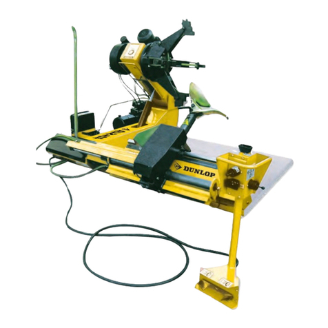
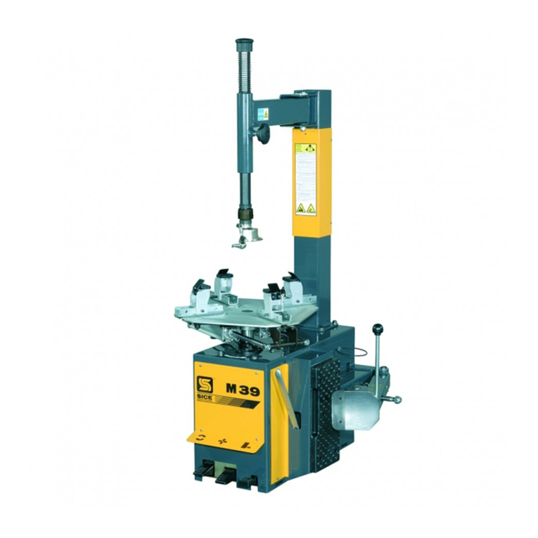
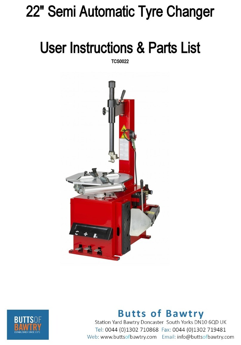
ATLAS PLATINUM PTC 500 User guide

Use and maintenance instruction manual
English/Italian/French/Deutch PTC500
PTC 500PTC 500
Original Instructions


3
INTRODUZIONE Pag. 5
1. DESCRIZIONE DELLA MACCHINA Pag. 7
Avvertenze di pericolo e divieti Pag. 8
2. GENERALITA' Pag. 9
2.1 Destinazione d'uso Pag. 9
2.2 Norme generali di sicurezza Pag.10
3. TRASPORTO Pag.11
4. DISIMBALLO Pag.11
5. INSTALLAZIONE Pag.12
5.1 Spazio necessario Pag.12
5.2 Posizionamento e montaggio Pag.13
5.3 Messa in servizio Pag.16
5.4 Test di funzionamento Pag.17
6. USO Pag.19
6.1 Stallonatura Pag.21
6.2 Smontaggio Pag.23
6.3 Montaggio Pag.27
7. GONFIAGGIO Pag.31
7.1Gonaggioconpistoletta Pag.31
7.2GonaggiocondispositivoGT Pag.35
8. RIPOSIZIONAMENTO Pag.39
9. ACCANTONAMENTO Pag.40
10. ROTTAMAZIONE Pag.40
11. MANUTENZIONE Pag.41
11.1 Avvertenze generali per la manutenzione Pag.41
12. TABELLA GUASTI RIMEDI Pag.45
13. DATI TECNICI Pag.47
14. SCHEMI ELETTRICI E PNEUMATICI Pag.48
Indice Generale - General Index
INTRODUCTION Page 5
1. DESCRIPTION OF THE MACHINE Page 7
Danger and prohibition warning signs Page 8
2. GENERAL Page 9
2.1 Intended use Page 9
2.2 General safety precautions Page 10
3. TRANSPORT Page 11
4. UNPACKING Page 11
5. INSTALLATION Page 12
5.1 Space required Page 11
5.2 Positioning and assembly Page 13
5.3 Commissioning Page 16
5.4 Operating tests Page 17
6. OPERATION Page 19
6.1 Breaking the bead Page 22
6.2 Removing the tyre Page 24
6.3 Mounting the tyre Page 28
7. INFLATING Page 32
7.1Inatingwithairlinegauge Page32
7.2InatingwithGTsystem Page36
8. MOVING Page 39
9. STORAGE Page 40
10. SCRAPPING Page 40
11. MAINTENANCE Page 41
11.1 General Maintenance warning Page 41
12. TROUBLE-SHOOTING Page 45
13. TECHNICAL DATA Page 47
14.
ELECTR. AND PNEUM. DIAGRAMS Page 48

4
Il presente manuale costituisce parte integrante del prodotto.
Prima di utilizzare lo smontagomme, leggere attentamente le avvertenze e le istruzioni contenute nel presente
libretto in quanto forniscono importanti indicazioni riguardanti la sicurezza d’uso e la manutenzione.
This manual is an integral part of the product.
Before using the tyre changer, read carefully the warnings and instructions contained in this manual since
they provide important information on operating safety and maintenance.
Le présent manuel fait partie intégrante du produit.
Avant d’utiliser le démonte-pneus, lire attentivement les instructions et les remarques du présent manuel
car elles fournissent des indications importantes sur la sécurité d’utilisation et l’entretien.
Dieses Handbuch ist Bestandteil des Produktes.
Bevor Sie das Reifenmontiergerät zum ersten Mal benützen, lesen Sie bitte aufmerksam die darin enthaltenen Anweisungen,
denn sie enthalten wichtige Hinweise zur Betriebssicherheit und Wartung.
Conservare con cura questo manuale per ogni ulteriore consultazione
Keep this manual for further reference.
Conserver très soigneusement ce manuel pour le consulter si nécessaire.
Bewahren Sie dieses Handbuch sorgfältig auf, damit Sie es jederzeit wieder konsultieren können!
FAC SIMILE

5
Conservare con cura questo manuale per ogni ulteriore consultazione
Keep this manual for further reference.
A) Platorello con Smartlock
B) Utensile Lever No Lever
C) Kit Gun
D) Braccio operante
E) Palo orizzontale
F) Palo verticale
G) Premitallone ausiliario destro
H) Stallonatore
I) Appoggi ruota
L) Premitallone ausiliario sinistro
M) Pedale comando stallonatore
N) Comando utensile leverless
O) Pedale comando invertitore
P) Pedale sollevatore
Q) Pedaledigonaggio
R) Selettore manuale Lever No Lever
S) Bloccaggio addizionale braccio orizzontale
1. DESCRIZIONE DELLA MACCHINA - DESCRIPTION OF THE MACHINE
A) Center clamping post+Smartlock
B) Lever no Lever mounting head
C) Inatinggun
D) Operating arm
E) Horizontal arm
F) Vertical arm
G) Pneumatic bead pressing system
H) Bead breaker
I) Wheel support
L) Rotating pneumatic pressing system
M) Bead breaker control pedal
N) Leverless control
O) Reverser control pedal
P) Wheel Lifter pedal
Q) Inatingpedal
R) Lever No Lever handle control
S) Additional horizontal arm locking plate
Fig. 1/ Abb. 1
A
B
C
D
E
F
G
H
L
M
I
N

6
AVVERTENZE DI PERICOLO - DANGER WARNING SIGNS - AVIS DE DANGER - GEFAHRENHINWEISE
Cod. 3037331
Cod. 3005410
Fig. 2
Cod. 3005414
Cod. 3016802
Cod. 3044184
Cod. 3019737
Cod. 3000048
Cod. 3002468
Cod. 3035727
Cod. 3025916
Cod. 3005416

7
2. GENERALITÀ
2.1 DESTINAZIONE D’USO.
• Lo smontagomme semi-automatico è stato progettato e realizzato esclusivamente per lo smontaggio e il montaggio
dei pneumatici dai/sui cerchi con dimensioni da 14" a 26" e diametro max. 1200 mm.
Qualsiasi altro uso è da considerarsi improprio e quindi irragionevole
• E’vietatoutilizzarelamacchinaper:raddrizzarecerchistallonarepneumaticiancoragonosporchi,rimuoverecerchietti
ruota
• In particolare IL COSTRUTTORE non può essere considerata responsabile per eventuali danni causati da usi non
esplicati in questo manuale e quindi impropri, erronei ed irragionevoli.
2. GENERAL
2.1 INTENDED USE
• The semi-automatic tyre changer has been designed and manufactured exclusively for removing and mounting
tyres from/onto rims from 14" to 26" and a maximum diameter of 1200 mm.
Any other use is to be considered incorrect and unreasonable.
•Itisforbiddentousethemachineforstraighteningrims,breakingbeadsofstillinatedordirtytyres,removingbeadwires.
•In particular The Manufacturer cannot be held responsible for any damage caused through the use of this tyre changer for
purposesotherthanthosespeciedinthismanual,andthereforeinappropriate,incorrectandunreasonable.
2. GENERALITES
2.1 DESTINATION
• Le démonte-pneus semi-automatique a été projeté et réalisé exclusivement pour le démontage et le montage des
pneus des/sur les jantes avec dimensions de 14" à 26" et diamètre max de 1200 mm.
Toute autre utilisation doit être considérée impropre et donc irraisonnée.
• Ilestinterditd’utiliserlamachinepour:redresserlesjantes,décollerdepneusencoregonésousales,enleverlestringles
du talon.
• Le constructeur ne peut pas être considérée responsable de dommages éventuels causés par des utilisations qui ne
sont pas expliquées dans ce manuel et par conséquent impropres et incorrectes.
2. ALLGEMEINES
2.1 VERWENDUNGSZWECK
Das halbautomatische Reifenmontiergerät wurde ausschließlich zumAb- und Neumontieren von Reifen von/auf Felgen geschaffen von 14"
bis 26" und einem Durchmesser bis zu 1200 mm,.
Jede anderweitige Verwendung ist unsachgemäß und deshalb unzulässig !
Die Maschine zum Felgenrichten oder zum Wulstabdrücken von noch aufgepumpten oder schmutzigen Reifen NICHT benutzen. Es ist
auch verboten, die Maschine zum Entfernen von Wulstkerne zu benutzen.
Der Hersteller haftet daher nicht, wenn durch Verwendungen, die in diesem Handbuch nicht vorgesehen und deshalb unsachgemäß, falsch
und unzulässig sind, Schäden entstehen.

8
INTRODUZIONE
Vi ringraziamo per aver acquistato un prodotto della Nostra linea di smontagomme semi-automatici. La macchina è realizza-
ta attraverso l’applicazione dei migliori principi in rispetto al concetto di qualità.
Peruncorrettofunzionamentoeperunalungaduratasaràsufcienteosservarelesempliciistruzionicontenutenel
presente manuale che dovrà essere letto e compreso nel modo più completo in ogni sua parte.
ANAGRAFICA DELLO SMONTAGOMME
Una completa descrizione del “Modello dello Smontagomme” e il “N.ro di Matricola” faciliterà il servizio della Nostra assi-
stenza e la spedizione di parti di ricambio. Per maggiore chiarezza e comodità ricordiamo i dati del Vostro smontagomme
nel riquadro sottostante. Qualora vi fossero delle discordanze fra i dati riportati nel presente manuale e quelli sulla targhetta
applicata allo smontagomme, faranno fede quelli sulla targhetta.
2.2 NORME GENERALI DI SICUREZZA.
L’uso dello smontagomme è consentito solo ed esclusivamente a personale esperto, appositamente
addestrato ed autorizzato.
•Ogniequalsiasimanomissioneomodicadell’apparecchiaturanonpreventivamenteautorizzatedalcostruttore
sollevano quest’ultimo da ogni responsabilità per danni derivati o riferibili agli atti suddetti.
• La rimozione o manomissione dei dispositivi di sicurezza comporta la decadenza immediata della garanzia e la
violazione delle Norme Europee per la Sicurezza.
• Lo smontagomme è corredato di decalcomanie di istruzione ed avvertenze progettate e realizzate per durare nel tempo.
Qualora venissero danneggiate o distrutte, l'utente deve richiederle subito al costruttore utilizzando i codici di pag.8
2.2 NORMES GENERALES DE SECURITE
L’utilisation du démonte-pneus est permise exclusivement à du personnel spécialisé, expressément
formé et autorisé.
•Leconstructeurn’estpasresponsabledesdommagescausésparlesappareilsquiontétémodiéssanssonautorisation
préalable.
•Lagarantieestimmédiatementnullesidesmodicationsoudestransformationssontapportéesauxdispositifsde
sécurité; celles-ci sont une violation des normes européennes pour la sécurité.
• Le démonte-pneus est équipé de décalcomanies d’instructions et d’avis de danger, projetées et réalisées pour durer dans le
temps. Si elles sont endommagées ou détruites, l’utilisateur doit les demander immédiatement au constructeur en utilisant
les codes de la page 8.
2.2 ALLGEMEINE SICHERHEITSNORMEN
Die Verwendung des Reifenmontiergerätes ist nur Personen gestattet, die entsprechende Erfahrung haben,
eingewiesen worden und zum Gebrauch befugt sind.
-Falls Veränderungen oder Eingriffe auf dem Gerät vorgenommen werden, die vom Hersteller nicht zuvor bewilligt worden sind, haftet
dieser nicht für Schäden, die auf diese zurückzuführen sind.
-Die Entfernung oder Veränderung von Sicherheitsvorrichtungen bewirkt den sofortigen Verfall der Garantie und stellt eine Verletzung der
Europäischen Sicherheitsnormen dar.
-Auf dem Reifenmontiergerät wurden Klebeetiketten mitAnweisungen und Warnungen angebracht, durch deren Beachtung die Lebensdauer
des Gerätes verlängert werden kann.
Werden diese beschädigt oder entfernt, müssen sie sofort beim Hersteller unter Angabe der Bestell-Nummern von Seite 8 angefordert
werden

9
3. TRASPORTO
• Lo smontagomme deve essere trasportato nell'imballo originale e mantenuto nella posizione indicata sull'imballo stesso.
• Lo spostamento della macchina imballata deve essere effettuato inforcando con un carrello elevatore di adeguate
capacità,neipuntiindicatidallagura3.
3. TRANSPORT
• The tyre changer must be transported in its original packaging and kept in the position shown on the package itself.
• The packaged machine may be moved by means of a fork lift truck of suitable capacity. Insert the forks at the points shown
ingure3.
3. TRANSPORT
• Le démonte-pneus doit être transporté dans son emballage et maintenu dans la position indiquée sur l’emballage même.
•Lamachineemballéedoitêtredéplacéesurlesfourchesd’unchariotélévateurd’unecapacitéappropriée,enléesaux
pointsindiquéssurlagure3.
3. TRANSPORT
Das Reifenmontiergerät darf nur in seiner Originalverpackung und in der auf der Verpackung
angegebenen Position transportiert werden.
Die verpackte Maschine darf nur mit einem dazu geeigneten Gabelstapler angehoben und
transportiert werden, wobei die Gabeln an den in Abb. 3 angegebenen Punkten einzuschieben
sind. Fig. 3
4. DISIMBALLO
Togliere il cartone di protezione e il sacchetto in nylon
Assicurarsi dell’integrità dell’apparecchio controllando che non vi siano parti visibilmente danneggiate o
mancanti facendo riferimento alla g. 1
In caso di dubbio non utilizzare la macchina e rivolgersi al proprio rivenditore.
4. UNPACKING
Remove the protective cardboard and the nylon bag.
Check that the equipment is in perfect condition, making sure that no parts are damaged or missing. Use g. 1 for
reference.
If in doubt do not use the machine and contact your retailer.
4. DEBALLAGE
Enlever le carton de protection et le sac en nylon.
Contrôler qu’il n’y ait pas de parties visiblement endommagées ou manquantes en se référant à la gure 1.
En cas de doute, ne pas utiliser la machine et s’adresser au revendeur autorisé.
4. AUSPACKEN DER MASCHINE
Schutzkarton und Plastikbeutel entfernen.
Kontrollieren, ob das Gerät intakt ist, ob keine sichtbaren Beschädigungen vorhanden sind oder Teile fehlen, siehe dazu Abb.1.
Im Zweifelsfalle die Maschine nicht benützen und den Verkäufer benachrichtigen.
Kg.220

10
5.3 MESSA IN SERVIZIO
Prima di effettuare gli allacciamenti, accertarsi che le caratteristiche dei propri impianti corrispondano a
quelle richieste dalla macchina.
• Se fosse necessario cambiare la tensione di funzionamento della macchina occorre intervenire sulla morsettiera (Cap. 14-
schema elettrico)
Interventi sull’impianto elettrico, anche se di lieve entità, richiedono l’intervento di personale
professionalmente qualicato.
• Collegarelamacchinaall’impiantod’ariacompressatramitel’attacco(Q)sporgentedallaparteposteriore(g.6)
•Collegare la macchina alla rete elettrica che deve essere dotata di fusibili di linea, di una buona presa a terra
come da norme vigenti e collegata ad un interruttore automatico di alimentazione (differenziale) tarato a 30 mA.
NOTA: Qualora lo smontagomme venga fornito senza spina elettrica, sarà cura dell'utente montarne una(almeno 16 A)
adeguata alla tensione della macchina e secondo le normative vigenti.
5.3 COMMISSIONING
Before making the connections, check that the characteristics of your systems correspond to those required
by the machine.
•If you have to change the machine’s operating voltage, make the necessary adjustments to the terminal board (Chap.14)
Even small jobs done on the electrical system must be carried out by professionally qualied personnel.
•Connect the machine to the compressed air system by means of the air connection (Q) that protrudes from the rear section
as shown in the diagram 6.
•Connect the machine to the electric network, which must be provided with line fuses, a good earth plate in complian-
ce with regulations in force and it must be connected to an automatic circuit breaker (differential) set at 30 mA.
Note: Should the tyre-changer be lacking in electric plug, so the user must set one,which is at least 16 A and which
conforms to the voltage of the machine, in compliance with the regulations in force.
5.3 MISE EN MARCHE
Avant d’effectuer les raccordements, vérier que les caractéristiques des installations correspondent à celles
demandées par la machine.
•S’il faut changer la tension de fonctionnement de la machine, intervenir sur le bornier (voir schéma électrique Chap. 14).
Les interventions sur l’installation électrique, même si elles sont peu importantes, doivent être effectuées par
du personnel qualié.
•Raccorderlamachineàl’installationd’aircompriméparleraccord(Q)situéàl’arrière(voirgure6).
•Relier la machine au reseau électrique, qui doit être equipé de fusibles de ligne et d’une prise de terre conformément aux
normes en vigueur. De plus, il faut relier la machine à un interrupteur automatique d’alimentation (différentiel) reglé à 30 mA.
NOTE: Si le demonte-pneus est dépourvu de che électrique, l’utilisateur devramonter une che qui soit proporsionnée
à la tension de la machine ( au moins 16 A) conformément aux normes en vigueur.
5.3 INBETRIEBNAHME
Vor dem Anschluß muß überprüft werden, ob die Eigenschaften der Betriebsanlagen den von der Maschine
geforderten Werten entsprechen.
-Falls die Betriebsspannung der Maschine geändert werden muß, entsprechend Schaltplan im Kap. 14 Klemmenbrett vorgehen.
(Auch kleinere) Eingriffe an der elektrischen Anlage dürfen nur von Fachpersonal vorgenommen werden.
-Maschine an das Druckluftnetz anschließen, hierzu den Anschlußstutzen (Q) verwenden, der gemäß Abbildung hinten hervorsteht.
Maschine vorschriftsgemäß an das Stromnetz anschließen. Das Stromnetz muß mit Schmelzsicherungen sowie mit einem guten
Erdschluß versehen werden. Dazu muß die Maschine an einen selbstätigen 30mAgeeichtenAusschalter (Differential) verbindet wer-
den.WICHTIG:Wenn das Reifenmontiergerät ohne Steckdose geliefert wird, muß der Verbraucher mindestens eine 16A Steckdose
anschließen. Diese muß an die Spannung der Maschine angemessen und gemäß der gültigen Bestimmungen sein.

11
Unpacking:
Removetheprotectivecardboard,removeallxingscrewandfreethetire-
changer from its original pallet.
Check the condition of the machine.
Note: All the most delicate surfaces of the tire- changer are coated by a
special rust-proof oil.
Some oil traces may leak after coating procedure: please, remove them
accordingly.
Theinstallationofthetirechangermustbecarriedoutbyprofessionallyqualiedpersonnel.
Twopersonsandproperliftingdevicearerequiredtocarryouttheinstallationsafely.
Gross weigth ~390 Kg.
Useliftingequipmentofsuitableload-bearingcapacitythatisabletoeasilytaketheweightofthetire
changer (at least 500 Kg capacity).
PlaceTire-Changerontoaleveled-out,smoothandnotslipperyoorwithasuitableloadcapacity.
2.2 GENERAL SAFETY PRECAU-
TIONS
5. INSTALLATION
5.1 SPACE REQUIRED
When choosing the place of installation be sure that it complies with current safety at work regulations.
•The semi-automatic tyre changer must be connected to the mains electric power supply and the compressed air system.
It is therefore advisable to install the machine near these power sources.
•Theplaceofinstallationmustalsoprovideatleastthespaceshowningure4/Asoastoallowallpartsofthema-
chine to operate correctly and without any restriction.
•If the machine is installed outside it must be protected by a lean-to.
The tyre changer with electric motor cannot be used in explosive atmospheres, unless it is a proper version.
500 mm
500 mm
500 mm
Fig. 4/A

12
Themachinewillbeprovidedwiththeneededxing
screws,asingleplasticwillcontain:
-5screwsM10x60mm(verticalarm)
-2screwsM10x40mm(verticalarm)
- 7 self locking nut M10 (vertical arm)
-1screwM16x100mm(Beadbreakerarm)
- 1 self lockin nut M16 (Bead breaker arm)
- 1 Spring (Bead breaker arm)
- 1 self lockin nut M16 (Horizontal arm)
- 2 shim (Horizontal arm)
-1oversizedwhasher(Horizontalarm)
Vertical Arm Installation
After unpacking the machine, mount the
vertical post on the machine’s body using
theprovidedbolts,andtightthemrmly.
-5screwsM10x60mm
- 4 self locking nut M10
2 wrench 17 mm are required
Usethetwoshorterboltsontherearofthe
vertical arm support.
-2screwsM10x40mm
- 2 self locking nut M10
2 wrench 17 mm are required

13
Bead Breaker Arm Installation
Install the Bead breaker arm in its housing
usingthededicatedscrew.
-1screwM16x100mm
- 1 self lockin nut M16
Do not tight the bolt yet.
Wheninsertingthecylinderrod(rstremo-
ve the special nut assembled on it) into the
rotatingpin,makesurethattheatsideof
the pin is positioned on the outer side of
themachine(wherethenutisgoingtobe
assembled again).
Install the special nut on the bead breaker
cylinder rod.
Tight it properly.
Allen wrench 8mm is required.

14
Install the spring using a plastic tie to pull it.
Tightthefulcrumxingbolt.
2wrench24mmarerequired
NOTE: Make sure the arm can move freely,
donotovertightthexingbolt,thearmhas
to be free to move and without excessive
play.
Horizontal arm Installation
Install the horizontal arm on the vertical
post support, make sure to place the provi-
deshimswiththemachine,atleast1piece
per side.
Note: in order to assemble the horizontal
arm,itisneededtoremoversttheadditio-
nal locking plate assembled on the C-sha-
ped support on the vertical arm.
Allen wrench 10 mm is required.
Insert the pin, using a hammer.
NOTE:Thisoperationcanbedifcult,ope-
rate carefully, making sure of the correct
aligment of each component.

15
Assembletheoversizedwasherandthe
self-locking nut on the fulcrum pin.
NOTE:Tightthexingnutmakingsurethe
armcanmovefreelyandwithoutplay.
24 mm wrench is required
Reassemble the additional locking plate,
usingthededicatedscrew,bushandwa-
sher.
NOTE: Make sure the pin on the horizontal
arm goes through the slot of the additional
locking plate.
Tightthescrewrmly.
Allen wrench 10mm is required.

16
Assembletheairtting(thesupplyline)on
the vertical arm.
Wrench 17mm is required
NOTE: make sure to use sealant on the
tting'sthread(Liquidthreadsealing,such
asLoctite,orTeonPTFEtape).
Kit gun, support and tool tray installation.
AssembletheKITGUNhosettingonthe
upper side of the vertical arm.
NOTE: make sure to use sealant on the
tting'sthread(Liquidthreadsealing,such
asLoctite,orTeonPTFEtape).
Adjustable wrench is required.
Complete the hoses connectionby plugging
the black and white hoses

17
Assemble the tool tray and the kit Gun
support on the machine body, using the
provided bolts.
The needed screws will be already assem-
bled on the machine’s body.
2 Wrench 17mm are required
Assemble the tool tray and the kit Gun
support on the machine body, using the
provided bolts.
The needed screws will be already assem-
bled on the machine’s body.
2 Wrench 17mm are required
Installtheplatformonthewheellift,using
theprovidedscrew,washerandbush.They
willbealreadyassembledontheplatform.
Allen wrench 8mm is required.
2 Wrench 17mm are required
Wheel lift installation

18
The Bead pressing System HP3-PW is
packed separately, the needed fastenings,
retainersandttingarecontainedinsideits
packing.
Removethelterlubricatorfromthema-
chine.
Make sure to install the dedicated seeger
ring and washer on the internal side of the
platform’s shaft.
They will be already assembled on the lift
pin.
Seeger pliers is required
Assemblethelifterpedal(withitssupport)
on the machine body (they are located
located inside the tire changer body, the
screwswillbealreadyassembledonthe
machine’s body).
13mm wrench is required
Assemble the pedal cover and reinstall the
side panel of the machine.
10mm wrench is required for the pedal
cover.
Pneumatic bead depressor system installation

19
Insert the double retainer into the slots pre-
sent on the tyre-changer body.
Install the bracket A on the rear side of the
tyre changer.
Insert the single retainer onto the bracket A.
Usethe3xingpointstoinstallthebead
pressing system.
A
Usetheshimtorecoverthegapbetween
the tire changer body and the bead pres-
sing system.
Tightthenuts,usingapowertoolorma-
nually.
17mm wrench is required.

20
Reassemble the Filter/Lubricator on the
rear of the HP3-PW.
NOTE: In order to supply compressed
airtoHP3-PW,usetheprovidedT-tting
(using the lubricated compressed air line).
Adjust the position of the anti-tipping foot.
The Manufacturer is not responsible for damages caused by electrical connection different from the origi-
nal indications.
Evensmalljobsdoneontheelectricalsystemmustbecarriedoutbyprofessionallyqualiedpersonnel.
Connect the tire changer to the compressed air system.
Thepneumaticnetworkoftheinstallationareamustbeprovidedwithan
airoutletfortheconstantsupplyof8barsofminimumworkingpressure.
Connectthetirechangertotheelectricpowersupplyline.
Theelectricnetworkoftheinstallationareamustbeprovidedwithadequateearthplateandcon-
nected to an appropriate automatic circuit-breaker set at 16 A.
Beforeconnectingthemachine,pleasecheckthatthecharacteristicsofyournetworks
correspond to those indicated by machine’s data-label.
Other ATLAS PLATINUM Tyre Changer manuals