manuals.online logo
Brands
  1. Home
  2. •
  3. Brands
  4. •
  5. AMT
  6. •
  7. Water Pump
  8. •
  9. AMT 3670-94 Assembly instructions

AMT 3670-94 Assembly instructions

Other AMT Water Pump manuals

AMT 316A-95 Assembly instructions

AMT

AMT 316A-95 Assembly instructions

AMT 489 Series Assembly instructions

AMT

AMT 489 Series Assembly instructions

AMT 5830 Assembly instructions

AMT

AMT 5830 Assembly instructions

AMT 4410-95 Assembly instructions

AMT

AMT 4410-95 Assembly instructions

AMT 4222-95 Assembly instructions

AMT

AMT 4222-95 Assembly instructions

AMT 2762-98 1-1/2HP Assembly instructions

AMT

AMT 2762-98 1-1/2HP Assembly instructions

AMT 5760-95 Assembly instructions

AMT

AMT 5760-95 Assembly instructions

AMT 490B-98 User manual

AMT

AMT 490B-98 User manual

AMT Crono S-PID 30 Operating instructions

AMT

AMT Crono S-PID 30 Operating instructions

AMT 07ES05C Series Assembly instructions

AMT

AMT 07ES05C Series Assembly instructions

AMT 3161-95 Assembly instructions

AMT

AMT 3161-95 Assembly instructions

AMT 5761-95B Assembly instructions

AMT

AMT 5761-95B Assembly instructions

AMT 4294-251 Assembly instructions

AMT

AMT 4294-251 Assembly instructions

AMT IPT 2P5X Series Assembly instructions

AMT

AMT IPT 2P5X Series Assembly instructions

AMT 4430-95 Quick setup guide

AMT

AMT 4430-95 Quick setup guide

AMT 4820-95 Assembly instructions

AMT

AMT 4820-95 Assembly instructions

AMT 2820-98 Assembly instructions

AMT

AMT 2820-98 Assembly instructions

AMT 3941-96 Assembly instructions

AMT

AMT 3941-96 Assembly instructions

AMT 3993-99 Assembly instructions

AMT

AMT 3993-99 Assembly instructions

AMT 5790-95 Assembly instructions

AMT

AMT 5790-95 Assembly instructions

AMT 3880-97 Assembly instructions

AMT

AMT 3880-97 Assembly instructions

AMT 569 Series Assembly instructions

AMT

AMT 569 Series Assembly instructions

AMT 3201-96 Assembly instructions

AMT

AMT 3201-96 Assembly instructions

AMT 25FP13AR User manual

AMT

AMT 25FP13AR User manual

Popular Water Pump manuals by other brands

Watershed Innovations HYDRAPUMP SMART FLEX Instructional manual

Watershed Innovations

Watershed Innovations HYDRAPUMP SMART FLEX Instructional manual

Graco Modu-Flo AL-5M instructions

Graco

Graco Modu-Flo AL-5M instructions

Messner MultiSystem MPF 3000 operating instructions

Messner

Messner MultiSystem MPF 3000 operating instructions

Xylem Bell & Gossett WEHT0311M Installation, operation and maintenance instructions

Xylem

Xylem Bell & Gossett WEHT0311M Installation, operation and maintenance instructions

WilTec 50739 Operation manual

WilTec

WilTec 50739 Operation manual

Franklin Electric Little Giant 555702 HRK-360S instruction sheet

Franklin Electric

Franklin Electric Little Giant 555702 HRK-360S instruction sheet

Ingersoll-Rand PD02P Series Operator's manual

Ingersoll-Rand

Ingersoll-Rand PD02P Series Operator's manual

VS ZJ Series Operating	 instruction

VS

VS ZJ Series Operating instruction

Flotec FPZS50RP owner's manual

Flotec

Flotec FPZS50RP owner's manual

SKF Lincoln FlowMaster II User and maintenance instructions

SKF

SKF Lincoln FlowMaster II User and maintenance instructions

Xylem Lowara LSB Series Installation, operation and maintenance instructions

Xylem

Xylem Lowara LSB Series Installation, operation and maintenance instructions

Water Duro Pumps DCJ500 Operating & installation instructions

Water

Water Duro Pumps DCJ500 Operating & installation instructions

Action P490 Operating instructions & parts manual

Action

Action P490 Operating instructions & parts manual

Flo King Permacore Reusable Carbon Bag Disassembly. & Cleaning Instructions

Flo King

Flo King Permacore Reusable Carbon Bag Disassembly. & Cleaning Instructions

ARO ARO PD15P-X Operator's manual

ARO

ARO ARO PD15P-X Operator's manual

Pumptec 112V Series Operating instructions and parts manual

Pumptec

Pumptec 112V Series Operating instructions and parts manual

Virax 262070 user manual

Virax

Virax 262070 user manual

Neptun NPHW 5500 operating instructions

Neptun

Neptun NPHW 5500 operating instructions

manuals.online logo
manuals.online logoBrands
  • About & Mission
  • Contact us
  • Privacy Policy
  • Terms and Conditions

Copyright 2025 Manuals.Online. All Rights Reserved.

Specications Information and Repair Parts Manual 3670-94
3670-253-00 1 4/2015
Please read and save this Repair Parts Manual. Read this manual and the General Operating Instructions carefully before attempting to assemble, install, operate
or maintain the product described. Protect yourself and others by observing all safety information. The Safety Instructions are contained in the General Operating
Instructions. Failure to comply with the safety instructions accompanying this product could result in personal injury and/or property damage! Retain instructions
for future reference. AMT reserves the right to discontinue any model or change specications at any time without incurring any obligation.
©2015 AMT Pump Company, A Subsidiary of The Gorman-Rupp Company, All Rights Reserved.
Periodic maintenance and inspection is required on all pumps to ensure proper operation. Unit must be clear of debris and sediment. Inspect for leaks and loose bolts. Failure to do so
voids warranty.
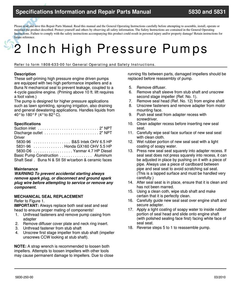
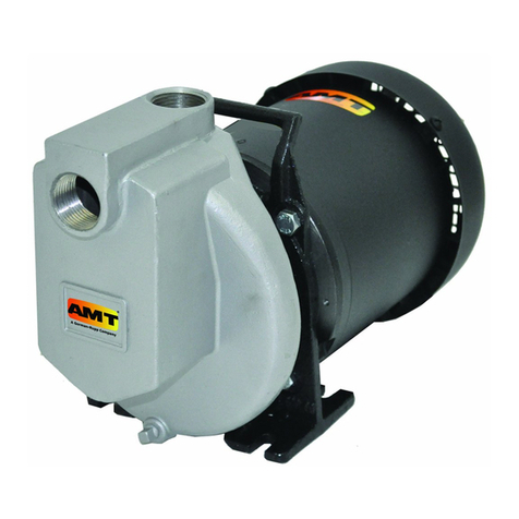
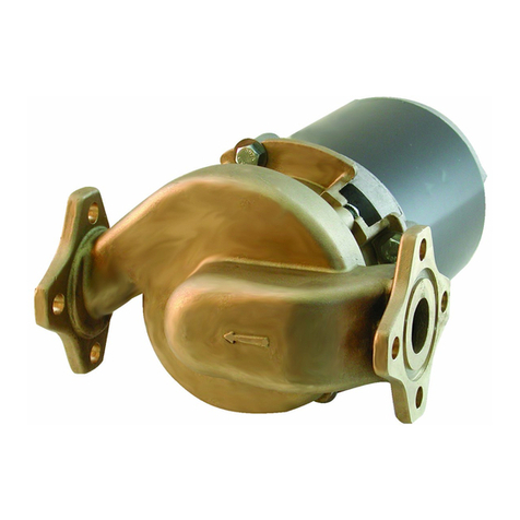
Bronze Marine Pump
Refer to pump manual 1808-634-00 for General Operating and Safety Instructions.
INSTALLATION
Because of crystallization and erosive material on shaft seal (Ref. No. 11),
installation of a seal wash is recommended to avoid premature leaks. Two
types may be used, a recirculated liquid type or a clean liquid type. Sometimes
a periodic seal cleaning is unavoidable.
Use pipe or hose to connect drain port on front of casing (Ref. No. 15) to seal
ush port on side of adapter (Ref. No. 9). Whenever pump is running, this re-
circulation line will ush seal.
Or, connect a line supplying clean liquid to seal ush port on adapter. Always
use an in-line check valve on this line. Flush as required.
MAINTENANCE
Disconnect from power source before servicing or inspecting the pump
for any reason. Failure to do so could result in fatal electrical shock!
MECHANICAL SEAL REPLACEMENT
Refer to Figures 1, 2 and 3.
IMPORTANT: Always replace both the seal seat and the seal head (Ref. No.
11) to ensure proper matching of components!
1. Unthread cap screws (Ref. No. 2) and remove casing (Ref. No. 15) and
o-ring (Ref. No. 14).
2. Unscrew impeller (Ref. No. 13) from shaft (Ref. No. 7). To keep the shaft
from turning, remove three screws holding the motor fan guard and
remove the guard. Loosen the screw clamping the fan to the motor shaft
and remove the fan. When the fan is removed, the shaft can be held using
vise grip pliers or other suitable means.
3. Remove the three hex nuts (Ref. No. 8) and remove the adapter (Ref.
No. 9).
4. Lay the adapter face down on a at stable surface and press the seal
cartridge from the adapter.
5. Pry the seal seat from the rear of the impeller with a screwdriver or other
suitable means.
6. Clean the recess in the adapter for the seal cartridge and the recess in the
impeller for the seal seat before inserting any new parts.
7. Inspect the ceramic face of the seal seat and carbon face of the cartridge
to insure they are clean and not marred.
DESCRIPTION
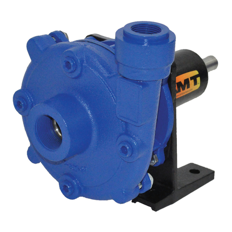
This non self-priming, low pressure, centrifugal pump is intended for liquid transfer, re-circulation and wash down applications in marine environments where no
suction lift is required. Pump is sized for saltwater (1.03 specic gravity) and features provisions for the installation of an automatic seal wash. This may extend
shaft seal life by retarding salt crystallization on seal wear face. Seal wash hose not included. For use with nonammable, non-abrasive liquids compatible with
pump component materials. Units are equipped with a TEFC (Totally Enclosed Fan Cooled), ball bearing, splash protected, capacitor start, 4 pole motor. Thermal
protection not provided. The motor has ON/OFF switch, standard plug and six foot cord.
Figure 1 - Mechanical Seal Replacement
Figure 2 - Mechanical Seal Replacement
Specications Information and Repair Parts Manual 3670-94
3670-253-00 2 4/2015
8. Press the new cartridge into the recess in the adapter. A sealing compound
(such as silicon or Permatex) may be used to assure a water tight t on the
outside of the cartridge.
9. Wet the rubber portion of the ceramic seat with a light coating of soapy
water.
10. Press the seal seat squarely into the cavity in the impeller. If the seal
seat does not press squarely into the cavity, it can be adjusted in place
by pushing on it with a piece of pipe. Always use a piece of cardboard
between the pipe and the seal seat to avoid scratching the face of the seal
seat. This is a lapped surface and must be handled very carefully.
11. After the seal seat is in place, check that it is clean and has not been
scratched or cracked.
12. Mount the adapter on the motor mounting face making sure the seal ush
part is approximately in the 1 o’clock position when facing the pump.
13. Replace the impeller and tighten, make certain any shims (Ref. No. 12)
previously used are in place.
14. Place the o-ring seal on the adapter and replace the casing. Replace and
tighten the cap screws.
15. Before proceeding to replace the fan and fan guard, turn the shaft to make
certain the impeller turns free and is not rubbing the casing.
16. If the shaft turns free replace the fan and fan guard. If it rubs the casing
follow steps 1 and 2. Remove any shims from the shaft and reassemble
following steps 13 thru 16.
SHIM ADJUSTMENT
When installing a replacement impeller (Ref. No. 13) or motor (Ref. No. 1), it
may be necessary to adjust the number of shims (Ref. No. 12) to ensure proper
running clearance between the impeller and the casing. Proceed as follows:
NOTE: A proper running clearance is less than 0.010”.
1. For impeller replacement, add one 0.010” shim in addition to those
removed originally.
2. For motor replacement, add two 0.010” shims in addition to the shims
removed during disassembly.
3. Reassemble the pump as described in steps 13 thru 16.
IMPORTANT: Be sure that the casing is snugly in place and check the shaft to
make sure it is turning freely. If it turns freely, check to be sure that the adapter
and casing are tted tight together. If they are not, tighten the fasteners (Ref.
No. 2) and recheck the shaft for free turning. Tighten carefully, turning the shaft
while tightening so that the motor bearings are not damaged in the event that
too many shims were installed. If shaft seizes before fasteners are completely
tight, disassemble the pump and remove one shim and repeat reassembly.
Bronze Marine Pump
Specications Information and Repair Parts Manual 3670-94
3670-253-00 3 4/2015
For Repair Parts contact dealer where pump was purchased.
Please provide following information:
-Model Number
-Serial Number (if any)
Part description and number as shown in parts list
Figure 3 - Repair Parts Illustrations
Bronze Marine Pump
Repair Parts List
Ref Part Number for Model
No. Description 3670-94 Qty
1 Motor 1626-017-00 1
2 Fastener 1718-001-00 9
3Washer 1766-020-00 4
4 Rubber Foot 1508-000-00 4
5 Nut 1774-000-00 4
6 Fastener 1736-005-00 2
7 Stub Shaft 3670-140-00 1
8 Nut 1772-012-00 3
9Adapter 3670-033-00 1
10 1/8” NPT Pipe Plug 1768-000-00 2
11 Seal Assembly - Buna N 1640-161-92 1
12 Shim Kit 1806-044-90 1
13 Impeller 3680-012-00 1
14 Casing O-Ring - Buna N 1582-000-00 1
15 Casing 3680-004-09 1