AMTAST AMT212 User manual

AMT212 Leeb Hardness Tester
Instruction Manaul
AMTAST USA INC

1
Contents
1 General description............................................................. 3
1.1 Features.................................................................................... 3
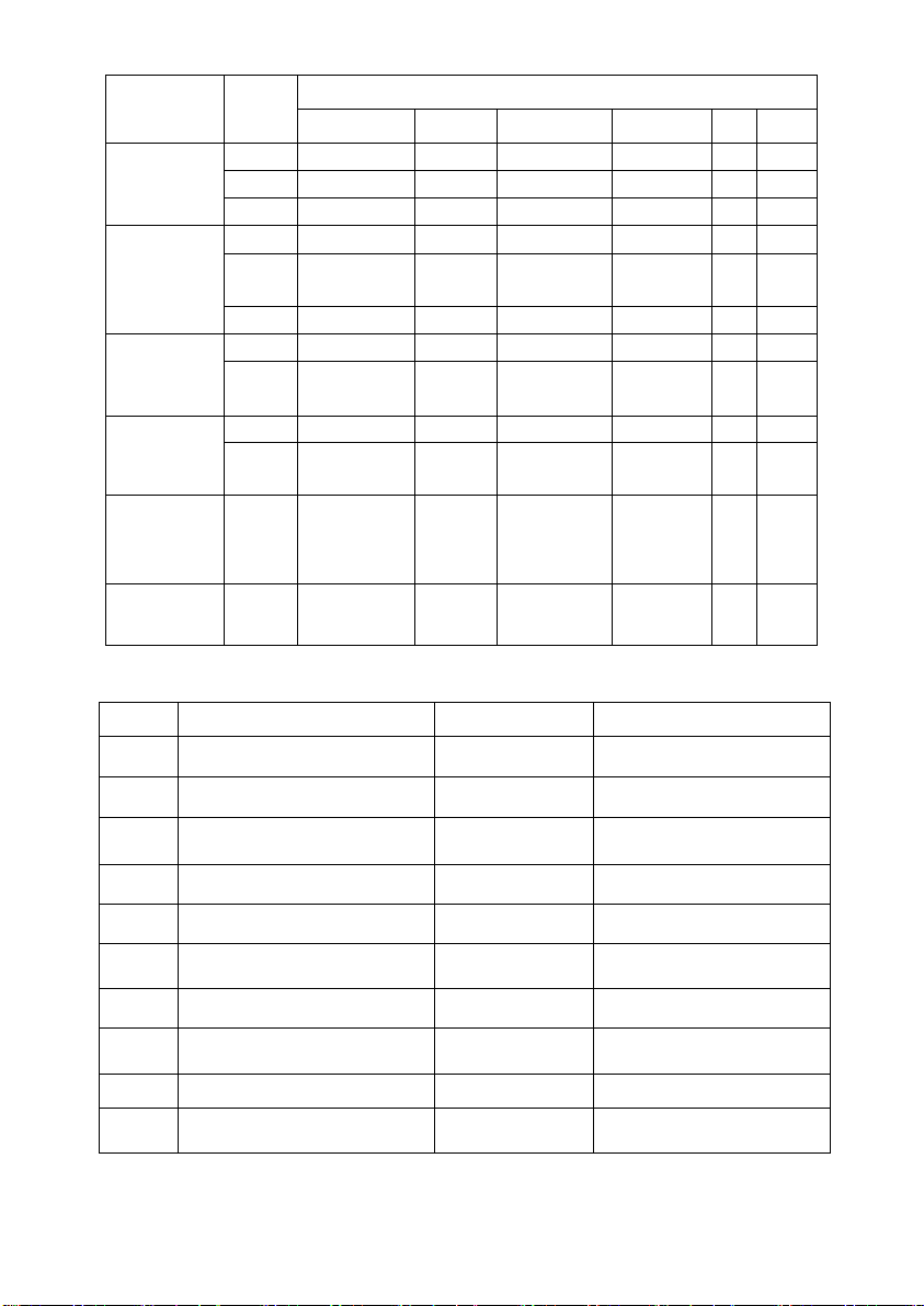
1.2 Main Application and Testing Range......................................... 3
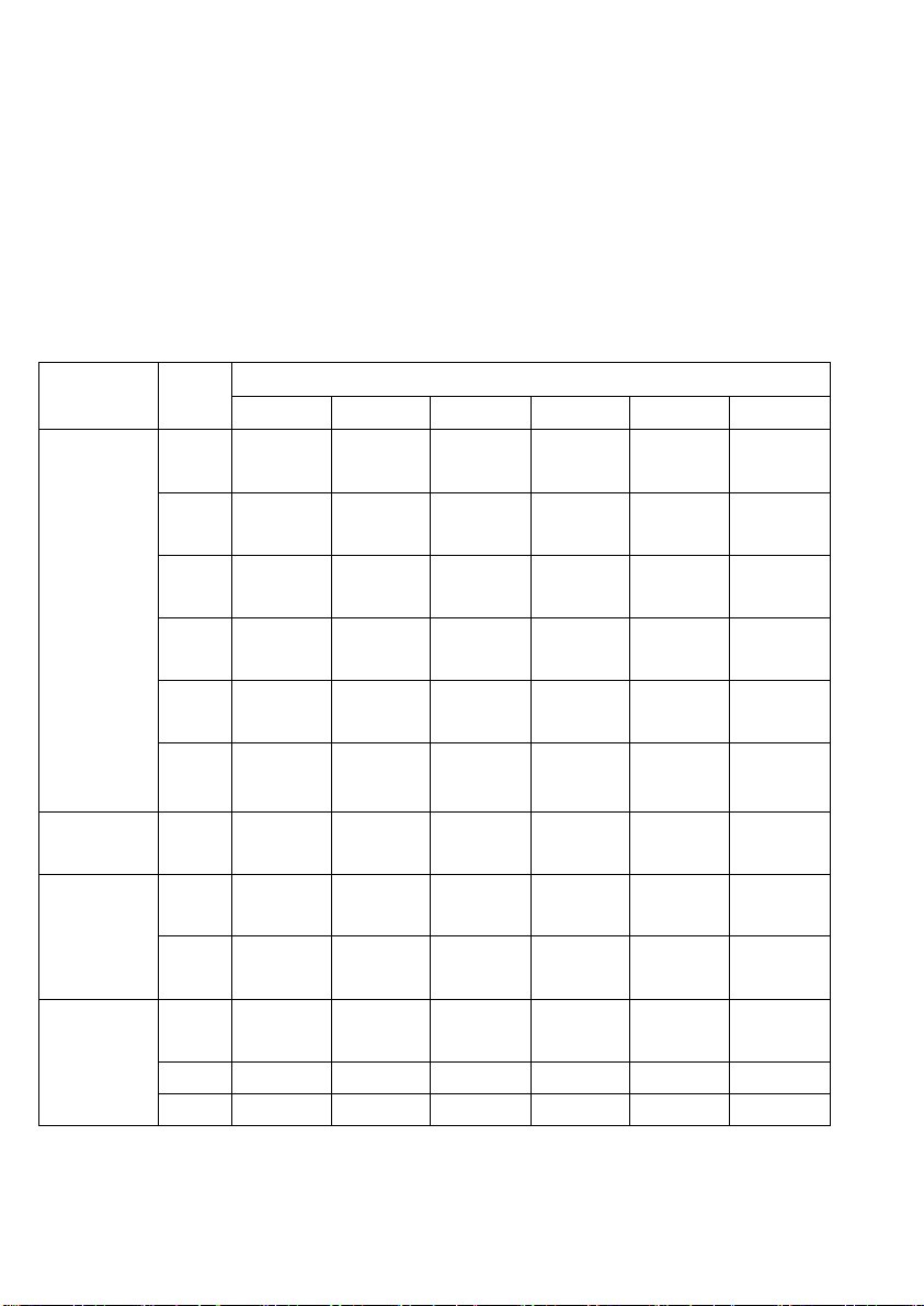
1.3 Types and specification............................................................. 6
1.4 Operating conditions:................................................................ 9
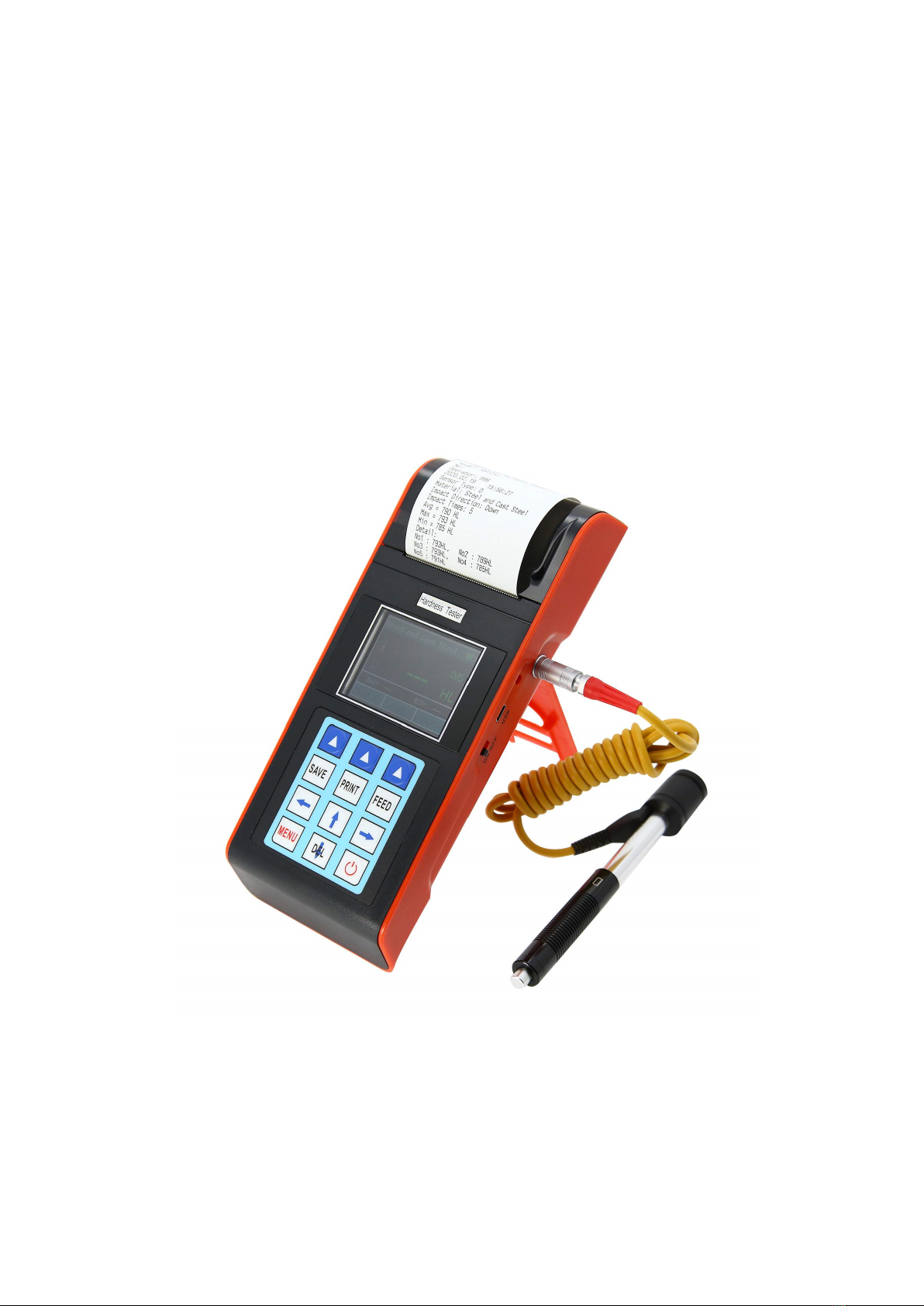
2 Structure features and Testing principle........................... 10
2.1 Structure features.....................................................................10
2.2 Testing principle......................................................................12
3 Technical capabilities ........................................................ 12
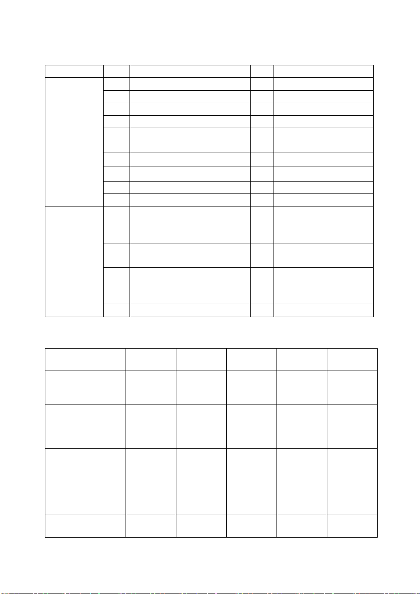
3.1 Specifications..........................................................................12
3.2 Dimension size and weight.......................................................13
4 Testing............................................................................... 13
4.1 Preparation and Inspection prior to testing ................................13
4.2 Testing ....................................................................................15
5 Special prompts................................................................. 18
6 Detail Testing procedures.................................................. 19
6.1 Start-up...................................................................................19
6.2 Turn On or turn off ..................................................................19
6.3 Testing ....................................................................................19
6.4 Menu structure diagram...........................................................22
6.5 Measuring condition setting .....................................................23
6.6 Print function...........................................................................25
6.7 Memory manager ....................................................................27
6.8 System Set ..............................................................................28
6.9 About software ........................................................................28
6.10 Software calibration...............................................................29
6.12 Turn off the power automatically............................................30
6.13 Battery Charge.......................................................................30
6.14 Battery Replacement..............................................................31
6.15 Paper Loading .......................................................................32
6.16 The connection of data communication cable..........................32

2
7 Trouble shooting................................................................ 33
8 Maintenance...................................................................... 33
8.1 Impact device..........................................................................33
8.2 Standard maintenance procedures.............................................33
9. Notice of Transportation and Storage.............................. 33
10. Non-warranty part......................................................... 33

3
1 General description
1.1 Features
⚫Color display (320×240 TFT) with adjustable backlight
⚫Converts to all common hardness scales (HV ,HB,HRC,HRB,HRA,HS),
and real time display HL value.
⚫Probe plug and test. Support hot plug, the probe can be set automatically
and automatic recognition function.
⚫Built in high capacity rechargeable lithium battery and charging control
circuit. Continuous working period of no less than 150 hours.
⚫Instrument with automatic sleep, automatic shutdown and other power
saving features.
⚫Menu operating, the operation is easy and convenient.
⚫With USB interface can be convenient, fast data exchange and parameter
settings.
⚫Equipped with 7 types of impact devices which need not to be
recalibrated when changing them, the system can identify the type of
impact device automatically.
⚫Max 500 groups(impact times:32~1)of data can be stored at internal
non volatile data storage.
⚫Upper and lower limit of hardness can be preset; When the tested value
exceeds the limits, alarm will send out automatically to make convenient
for the requirements of batch measurements.
⚫Test values software calibration function.
⚫Material of “cast steel” is added; HB values can be read out directly
when D/DC impact device is used to measure “cast steel” work piece.
⚫Thermal printer integrated, convenient for in field printing.
⚫Software of PC can be installed according to the requirements of user,
the function will be more powerful to satisfy the more strict demands of
quality control and management.
1.2 Main Application and Testing Range
1.2.1 Main Application
⚫The assembled machinery and permanently installed parts
⚫Die cavity of molds
⚫Heavy work piece
⚫Failure analysis of pressure vessel, steam turbo-generator set and other
equipment

4
⚫Narrow testing space where work piece installed
⚫Bearings and other parts
⚫Cases which require the test result with normalized original recording
⚫Material identification of the metal material warehouse
⚫Quick tests of large range and multipoint measuring positions for heavy
workpiece
1.2.2 Testing Range
Testing range see table 1 and table 2.
Table 1
Material
Hardness
method
Impact device
D/DC
D+15
C
G
E
DL
Steel and
cast steel
HRC 17.9~
68.5
19.3~
67.9
20.0~
69.5 22.4~
70.7
20.6~
68.2
HRB 59.6~
99.6 47.7~
99.9 37.0~
99.9
HRA 59.1~85.
8 61.7~
88.0
HB 127~
651 80~638 80~683 90~646 83~663 81~646
HV 83~976 80~937 80~996 84~
1042 80~950
HS 32.2~
99.5
33.3~
99.3
31.8~
102.1 35.8~
102.6
30.6~
96.8
Hammered
steel HB 143~650
Cold work
tool steel
HRC 20.4~
67.1
19.8~
68.2
20.7~
68.2 22.6~
70.2
HV 80~898 80~935 100~
941 82~
1009
Stainless
steel
HRB 46.5~
101.7
HB 85~655
HV 85~802
Table 1

5
Material Hardness
method Impact device
D/DC D+15 C G E DL
Gray cast
iron
HRC
HB 93~334 92~326
HV
Nodular
cast iron
HRC
HB 131~387 127~
364
HV
Cast
aluminum
alloys
HB 19~164 23~210 32~168
HRB 23.8~84.6 22.7~85.0 23.8~
85.5
Brass(copp
er-zinc
alloys)
HB
40~173
HRB 13.5~95.3
Bronze
(copper-alu
minum/cop
per-tin
alloys)
HB 60~290
Wrought
copper
alloys HB 45~315
Table 2
No. Material HLD Strength σb(MPa)
1 Mild steel 350~522 374~780
2 High-carbon steel 500~710 737~1670
3 Cr steel 500~730 707~1829
4 Cr-V steel 500~750 704~1980
5 Cr-Ni steel 500~750 763~2007
6 Cr-Mo steel 500~738 721~1875
7 Cr-Ni-Mo steel 540~738 844~1933
8 Cr-Mn-Si steel 500~750 755~1993
9 Super strength steel 630~800 1180~2652
10 Stainless steel 500~710 703~1676

6
1.3 Types and specification
No. Remarks
Standard
Delivery
1 Main unit 1
2 D type impact device 1
3
Small supporting ring
1
4 Nylon brush (A) 1
5 High value Leeb test
block 1
6
Battery Charger
1 9V 1000mA
7
Paper for printing
1
8
Communication cable
1
9 DataView Software 1
Additional
Optional
Delivery
1 Nylon brush (II)In case of choosing
G type impact
device
2
Various non-conventional
type of impact devices
See table 3
3 Various non-conventional
type of impact supporting
ring See table 4
4
Table 3
Non conventional
impact devices
DC(D)/D
L D+15 C G E
Impacting energy
Mass of impact
body
11Mj
5.5g/7.2g
11mJ
7.8g
2.7mJ
3.0g
90mJ
20.0g
11mJ
5.5g
T
est tip Hardness
Diameter of test tip
Material of test tip
1600HV
3mm
Tungsten
carbide
1600HV
3mm
Tungsten
carbide
1600HV
3mm
Tungsten
carbide
1600HV
5mm
Tungsten
carbide
5000HV
3mm
synthetic
diamond
Impact device
Diameter
Impact device
Length
Impact device
Weight
20mm
86(147)/ 75mm
50g
20mm
162mm
80g
20mm
141mm
75g
30mm
254mm
250g
20mm
155mm
80g
Max. hardness of
workpiece 940HV 940HV 1000HV 650HB 1200HV

7
Mean roughness of
workpiece surface of
the Ra 1.6μm 1.6μm 0.4μm 6.3μm 1.6μm
Min. weight of
sample
Measure directly
Need support firmly
Need coupling tightly
>5kg
2~5kg
0.05~2kg
>5kg
2~5kg
0.05~2kg
>1.5kg
0.5~1.5kg
0.02~0.5kg
>15kg
5~15kg
0.5~5kg
>5kg
2~5kg
0.05~2kg
Min. thicknessof
sample coupling
tightly
Min.layer thickness
for surface harden
5mm
≥0.8mm
5mm
≥0.8mm
1mm
≥0.2mm
10mm
≥1.2mm
5mm
≥0.8mm
Size of tip indentation
Hardness
300HV
Indentation
diameter 0.54mm 0.54mm 0.38mm 1.03mm 0.54mm
Indentation
depth 24μm 24μm 12μm 53μm 24μm
Hardness
600HV
Indentation
diameter 0.54mm 0.54mm 0.32mm 0.90mm 0.54mm
Indentation
depth 17μm 17μm 8μm 41μm 17μm
Hardness
800HV
Indentation
diameter 0.35mm 0.35mm 0.35mm -- 0.35mm
Indentation
depth 10μm 10μm 7μm -- 10μm
Available type of
impact device
D:
General test
DC:
Hole or
hollow-cylin
drical test
DL:
Slender
narrow
groove or
hole test
D+15:
groove or
reentrant
surface
C:
small,
light, thin
parts or
surface of
hardend
layer
G:
large,
thick,
heavy or
rough
surface
steel
E:
super high
hardness
material

8
Table 4
No. Code Type
Sketch of
non conventional
supporting ring Remarks
1 03-03.7 Z10-15
For testing cylindrical
outside surface
R10~R15
2 03-03.8 Z14.5-30
For testing cylindrical
outside surface
R14.5~R30
3 03-03.9 Z25-50
For testing cylindrical
outside surface
R25~R50
4 03-03.1
0 HZ11-13
For testing cylindrical inside
surface
R11~R13
5 03-03.1
1 HZ12.5-17
For testing cylindrical inside
surface
R12.5~R17
6 03-03.1
2 HZ16.5-30
For testing cylindrical inside
surface
R16.5~R30
7 03-03.1
3 K10-15
For testing spherical outside
surface
SR10~SR15
8 03-03.1
4 K14.5-30
For testing spherical outside
surface
SR14.5~SR30

9
9 03-03.1
5 HK11-13
For testing spherical inside
surface
SR11~SR13
10 03-03.1
6 HK12.5-17
For testing spherical inside
surface
SR12.5~SR17
11 03-03.1
7 HK16.5-30
For testing spherical inside
surface
SR16.5~SR30
12
03-03.1
8 UN
For testing cylindrical
outside surface,
radius adjustable
R10~∞
1.4 Operating conditions:
Ambient temperature: -10℃~40℃
Relative humidity: ≤90%
No vibration, no strong magnetic field and no corrosive medium and heavy
dust in ambient environment.

10
2 Structure features and Testing principle
2.1 Structure features
2.1.1 Hardness Tester
1: Main unit
2: Impact device
2.1.2 Main unit
1: Socket of impact device 2: Paper compartment cover
3: TFT display 4: Keypad 5: Power jack
6: Socket of USB 7 Battery switch 8 Product label
9 Serial Number 10.Battery compartment cover
2
1
7
6
5
4
3
1
2
10
9
8

11
2.1.3 D type impact device
1 2 3 4 5 6 7
1: Release button 2: Loading sheath 3: Guide tube 4: Coil part
5: Connection cable 6: Impact body 7: Support ring
2.1.4 Non conventional types of impact devices
DC DL C D+15 E G

12
2.2 Testing principle
Let a impact body whose weight is definite rush into the surface of sample,
the hardness value comes from the rate of rebound velocity and rush velocity
at 1mm distance from testing surface. The calculation formula is following:
HL=1000×VB/ VA
In which: HL——Leeb hardness value
VB——Rebounding velocity of the impact body
VA——Impacting velocity of the impact body
Output signal diagram of the impact device is as following.
3 Technical capabilities
3.1 Specifications
⚫Measuring range: HLD (170-960),HRC (17.9-69.5),HB (19-683),HV
(80-1042),HS (30.6-102.6),HRA(59.1-88),HRB (13.5-101.7)
⚫Measuring direction: 360°
⚫Hardness scale: HL, HB, HRB, HRC, HRA, HV, HS
⚫Display: TFT, 320×240 matrix
⚫Printing paper: width is (57.5±0.5)mm, diameter is 30mm
⚫Data memory: 500 groups (impact times: 32~1)
⚫Range of upper and lower limit: the same as measuring range
⚫Working Battery : 7.4V LithiumIon
⚫Battery charger: 9V/1000mA
⚫Full Charger power time:3~5 hour.
⚫Continuous working period: approx. 150 h
⚫Communication interface: USB
⚫Accuracy and repeatability of displayed value, see table 5.

13
3.2 Dimension size and weight
3.2.1 Dimension 209×85×45mm (main unit)
3.2.2 Weight approx. 0.6kg (main unit);
Table 5
No.
Type of
impact
device
hardness value of
standard Leeb
hardness block
Error of
displayed
value
Repeatability of
displayed value
1 D
760±30HLD
±6 HLD
6 HLD
2 DC
3 DL
4 D+15
5 G
6 E
7 C
4 Testing
4.1 Preparation and Inspection prior to testing
4.1.1 The preparation of workpiece surface
The preparation for workpiece surface should comply with the relevant
requirements specified in table 3
⚫During the preparation for sample, the affect to surface hardness of
sample caused by overheating, cold processing and etc. should be
avoided as far as possible.
⚫If the surface to be tested is too rough, measuring error will appear. So
the surface of the sample must have metallic luster and the surface must
be flat, smooth and have no oil dirt.
⚫Curved surface: it is better that the testing surface of workpiece is plane.
When the curvature radius R of the curved surface to be tested is less

14
than 30mm (for D, DC, D + 15, C, E and DL type impact device) and
less than 50mm (for G type impact device), a small support ring or non
conventional support ring should be used.
⚫workpiece supporting
—— Support is not necessary for heavy test workpiece
—— The workpiece with medium weight must be placed on flat and
solid plane, and it must be placed stably without any shaking.
⚫Enough thickness of workpiece is necessary, and the min. thickness
should comply with the specification in table 3.
⚫As for test piece with hardened surface layer, the depth of hardened layer
should comply with table 3.
⚫Coupling
——The workpiece with lightweight must be firmly coupled with the
support; both coupled surface must be flat, smooth and the coupling
agent should not be too much. The measuring direction must be vertical
to the coupled surface.
——When the workpiece is a large area plate, long rod or bending piece,
it can be deformed and become unstable even the weight and the
thickness is heavy and the test value may not be accurate. So it should be
reinforced or supported at the back of the workpiece.
⚫Self magnetism of workpiece should be less than 30 Gauss.
4.1.2 System setting of tester
Specific procedures for setting, refers to 6.9.
4.1.3 Measuring condition setting of tester
Specific procedures for setting, refers to 6.5.

15
4.2 Testing
⚫A standard hardness block should be used to check the the tester prior to
the testing; and the reading value error and repeatability should not be
more than the specification in table 5.
Note: the hardness value of standard hardness test block can be
measured via a Leeb hardness tester which had been calibrated; five
times of measuring should be carried out in direction of vertical down
and the arithmetic mean of five values should be used as the hardness
value of standard hardness test block. If the value exceeds the standard
range, it can be calibrated via user calibration function.
4.2.1 Start-up
⚫Insert the impact device plug into the socket of impact device located on
the right of the tester.
⚫Press 【】key to turn on the power, then the tester enters into the
measuring status.
4.2.2 Loading
⚫Push down the loading sheath to lock the impact body; for DC type
impact device, the loading bar can be attracted on testing surface and
insert DC type impact device into loading bar until the stop position, then
loading has been finished.
⚫Press tightly the support ring of impact device on the surface of test
sample, the direction of impact should be vertical with testing surface.

16
4.2.3 Testing
⚫Press down the release button on the top of the impact device to make a
test. At this point, the test sample, impact device and the operator are all
required to be stable; and the force direction should comply with the axis
of the impact device.
⚫Five measurements should be carried out per measuring position of test
sample. The divergence of data should be not exceeds ±15HL of mean
value.
⚫Distance between any two indentations, or the distance between any
indentation center and the edge of test sample should be in accordance
with the specification of table 6.
⚫For any special material, a comparative test must be performed to obtain
relevant conversion relation if Leeb hardness value accurately conversing
to other type of hardness value is required. Procedures are as following:
tests are made on the same test sample via Leeb hardness tester which
recalibrated well and relevant hardness meter respectively; for each
hardness value, five points which uniformly distributed around hardness
indentation should be chosen to make tests, and tests for three (at least)
indentations should be made; the mean value of Leeb hardness and the
mean value of relevant hardness will be act as relevant values
respectively to make a comparative hardness curve. Three groups
corresponding data should be included at least in comparative curve.
Table 6
Type of
impact
device
The distance of two
indentations center
The distance between
indentation center and edge of
test piece
No less than No less than
D、DC 3 5
DL 3 5
D+15 3 5
G 4 8
E 3 5
C 2 4

17
4.2.4 Read measured value
4.2.5 Print out result
For specific setting method, see 6.3.3 and 6.6.
4.2.6 Press 【】key to turn off
4.2.7 The processing of testing results
The mean value of five valid testing points can be served as a testing data of
Leeb hardness.
4.2.8 The express of testing results
⚫Hardness value will be displayed ahead of HL (the symbol of Leeb
Hardness), and type of impact device will be displayed back of HL. For
example, 700HLD expresses that the Leeb hardness is 700 by means of
the measurement made by D type impact device.
⚫For other type hardness which changed from Leeb Hardness value,
corresponding hardness symbol should be added ahead of Leeb hardness
symbol. For example, 400HVHLD expresses that the Vickers hardness
value is 400, which changed from Leeb hardness value measured by D
type impact device.
Note: HL values which measured by various impact devices are various.
For example: 700HLD
≠
700HLC.

18
5 Special prompts
⚫Replacing impact device must be performed under the condition of turn
off, otherwise the impact device type can not be identified automatically,
and even it is possible to cause the damage of circuit board of the tester.
⚫In normal condition, the current measured value can be printed or stored
if the 【Impact times】value which had been set is not satisfy. If the
printing and storing are required at this point, 【Average】key can be
press down to finish measurement, then printing can be carried out.
⚫The functions of 【Auto Save】, 【Auto Print】, and【Auto Trans.】will
be inactive in case of pressing down 【Average】key to finish
measurement in advance.
⚫Only D and DC type impact device have strength measuring function so
that 【Hard/σb】setting can not be changed if other type impact devices
are used; if the setting has been changed into 【σb】via D/DC type
impact device, the 【Hard/σb】setting will be changed into 【Hard】
when other impact devices had been installed instead of D/DC type
impact device.
⚫When 【σb】has been set, hardness scale will not been set (cursor will
skip off 【Hardness Scale】).
⚫Not all materials can be changed into every hardness scale, hardness
scale will return to Leed hardness (HL) automatically after material has
been changed. So 【Material 】will be set firstly when setting
measurement parameters, and 【Hardness Scale 】should be set
subsequently.

19
6 Detail Testing procedures
6.1 Start-up
Press 【】key to turn on the tester, The screen will display the relevant
information into the measurement state.
6.2 Turn On or turn off
Tester can be turn on or trun off by press 【】key in any display status.
6.3 Testing
The tester will enter the main display interface after turn on, as the following
figure.
The measured values are displayed with big font in this interface, and multiple
shortcut key operation functions supplied.
6.3.1 Explanation of the main display interface
Battery information: displaying rest capacity when no charging, and
displaying charging degree when charging.
Impact direction: current impact direction.
Average value indicator: average value will be displayed when impact times
setting has been achieved.
Hardness scale: the hardness scale of current measuring value.
Measured value: current single measured value (without average value
indicator), current average value (with average value indicator). It expresses
the value is more than conversion or measuring range when is displayed;
and it expresses the value is lower than conversion or measuring range when
is displayed.
Material: material that has been set currently.
Impact times: impact times that has been finished will be displayed when
measuring; Impact times that has been set will be displayed when impact
Impact
Direction
Material
Impact Type
Statistics
Hardness Scale
Battery
Information
Average value
Function key
Table of contents
Other AMTAST Test Equipment manuals
Popular Test Equipment manuals by other brands

IKONIX
IKONIX Associated Research Hypot 3805 quick start guide

Megger
Megger SVERKER 750 user manual

Gedore
Gedore CL10 operating instructions

Midtronics
Midtronics EXP-925 instruction manual

Excel Technology
Excel Technology SYNRAD FH Series Operator's manual

Balluff
Balluff MICROPULSE BTL7-A-CB02 Series manual

WIKA
WIKA CPD8500 operating instructions

LeCroy
LeCroy WaveMaster 8600A Operator's manual

Baker Hughes
Baker Hughes Druck DPI 620 Genii Safety Instructions and User Guide

Tetra
Tetra WaterTest Set Plus manual

AlcoSense
AlcoSense Zero user manual

Gossen MetraWatt
Gossen MetraWatt PROFITEST H+E TECH operating instructions