Note: The specifications are subject to change without 5
notice.
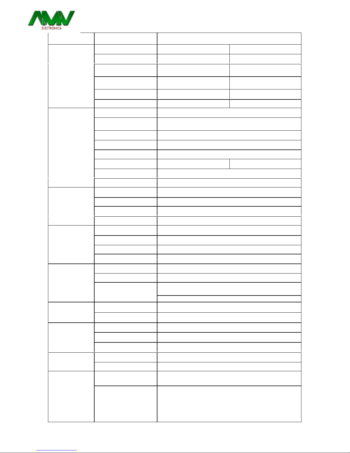
Electrical Performance
Electrical Specification MODEL
Item AMV OND1000-24-C1 AMV OND1000-48-C1
Voltage 24VDC 48 VDC
Input Over-Voltage
Protection 30-34 VDC 60-68 VDC
Input Under-Voltage
Protection 18-22 VDC 36-44 VDC
Voltage Range 18-34 VDC 36-68 VDC
Input
Characteristics
No Load Current 0.6 A 0.35 A
Continuous Output Power 1000 W
Maximum output Power
(3Min) 1150 W
Surge Power 2000 W
Frequency 50 / 60 Hz +/-0.05
Output Voltage 194-246 VAC (User-selectable)
Efficiency (Full Load) 90% 91%
Short-Circuit Protection Yes, Ipk
Output
Characteristics
Output Waveform Pure Sine Wave (THD < 2%)
LCD Panel 2 Lines LCD Panel with keypad for navigation
LED Indicator Red/Orange/Green LED
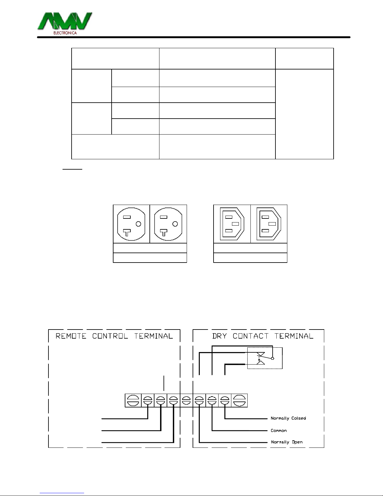
Dry Contact Terminal By a relay
Signal and Control
Remote Control Terminal Controls the inverter ON / OFF operation
Input Protection Over/Under Voltage, Reverse Polarity (Internal Fuse)
AC Output Protection Short-circuit, Overload
AC Input Protection 6Amp Circuit Breaker
Protection
Temperature protection Shutdown (Internal temperature S65° C)
Relay Specification 12 Amp/250 VAC
Bypass relay On Line/Off Line (Haphazard, Normal, Exacting) selectable
From AC bypass mode(0ff-iine Mode): S9mS
From DC to AC inverter mode(0n-line Mode):g7mS
Transfer Relay
Switching Time
Full Load 0° C -50° C
Operating
Temperature Storage -30° C~70° C
Failure Indication Buzzer alarm and dry contact
Switches On when Temperature = 55° C or Load=30
Fan Operation and
Indicator
Switches Off when Temperature =45° C and Load=20
Size (WXHXD) 19"x1.71"x13.6"(482.6mmX43.5mmX345mm)
Mechanical
Specification Weight 5.8 Kgs (12.7 Lbs)
Safety Standards Meets UL 60950 Meets EN60+950-1
Safety and EMI/ EMC
EMC standards FCC CLASS B EN55022 1998+A1 2000+A2 2003 CLASS B
EN55024: 1997+A1: 2001+a2 :2003
EN61000-3-2: 2006 Class A
EN61000-3-3: 11995+A1:2001