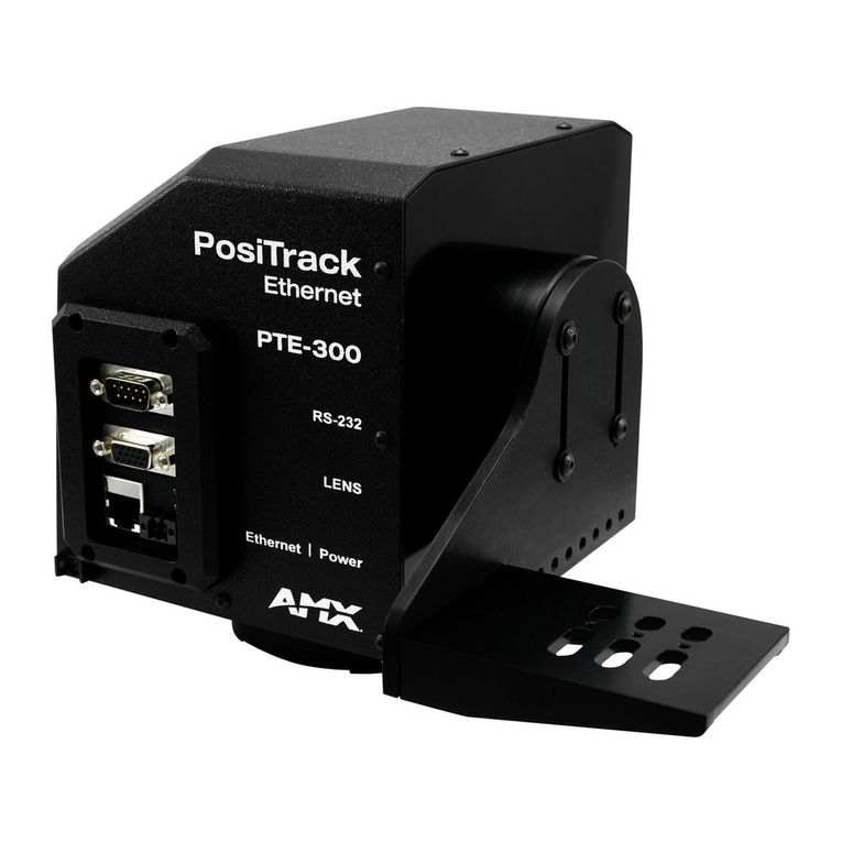
AMX PTE-300 Parts list manual

Operation/Reference Guide
Camera Controllers
PTE-300
Pan/Tilt Ethernet Camera Control Head
Last Updated: 1/10/2008

AMX Limited Warranty and Disclaimer
AMX warrants its products to be free of defects in material and workmanship under normal use for three (3) years from
the date of purchase from AMX, with the following exceptions:
• Electroluminescent and LCD Control Panels are warranted for three (3) years, except for the display and touch
overlay components that are warranted for a period of one (1) year.
• Disk drive mechanisms, pan/tilt heads, power supplies, and MX Series products are warranted for a period of one
(1) year.
• AMX Lighting products are guaranteed to switch on and off any load that is properly connected to our lighting
products, as long as the AMX Lighting products are under warranty. AMX does guarantee the control of dimmable
loads that are properly connected to our lighting products. The dimming performance or quality cannot be
guaranteed due to the random combinations of dimmers, lamps and ballasts or transformers.
• Unless otherwise specified, OEM and custom products are warranted for a period of one (1) year.
• AMX Software is warranted for a period of ninety (90) days.
• Batteries and incandescent lamps are not covered under the warranty.
This warranty extends only to products purchased directly from AMX or an Authorized AMX Dealer.
All products returned to AMX require a Return Material Authorization (RMA) number. The RMA number is obtained
from the AMX RMA Department. The RMA number must be clearly marked on the outside of each box. The RMA is
valid for a 30-day period. After the 30-day period the RMA will be cancelled. Any shipments received not consistent
with the RMA, or after the RMA is cancelled, will be refused. AMX is not responsible for products returned without a
valid RMA number.
AMX is not liable for any damages caused by its products or for the failure of its products to perform. This includes any
lost profits, lost savings, incidental damages, or consequential damages. AMX is not liable for any claim made by a
third party or by an AMX Dealer for a third party.
This limitation of liability applies whether damages are sought, or a claim is made, under this warranty or as a tort claim
(including negligence and strict product liability), a contract claim, or any other claim. This limitation of liability cannot
be waived or amended by any person. This limitation of liability will be effective even if AMX or an authorized
representative of AMX has been advised of the possibility of any such damages. This limitation of liability, however, will
not apply to claims for personal injury.
Some states do not allow a limitation of how long an implied warranty last. Some states do not allow the limitation or
exclusion of incidental or consequential damages for consumer products. In such states, the limitation or exclusion of
the Limited Warranty may not apply. This Limited Warranty gives the owner specific legal rights. The owner may also
have other rights that vary from state to state. The owner is advised to consult applicable state laws for full
determination of rights.
EXCEPT AS EXPRESSLY SET FORTH IN THIS WARRANTY, AMX MAKES NO OTHER WARRANTIES,
EXPRESSED OR IMPLIED, INCLUDING ANY IMPLIED WARRANTIES OF MERCHANTABILITY OR FITNESS FOR
A PARTICULAR PURPOSE. AMX EXPRESSLY DISCLAIMS ALL WARRANTIES NOT STATED IN THIS LIMITED
WARRANTY. ANY IMPLIED WARRANTIES THAT MAY BE IMPOSED BY LAW ARE LIMITED TO THE TERMS OF
THIS LIMITED WARRANTY.

Table of Contents
i
PTE-300 PosiTrack Ethernet Camera Controller
Table of Contents
PTE-300 Pan/Tilt Ethernet Camera Control Head ...............................................1
Overview ........................................................................................................................... 1
Specifications ................................................................................................................... 2
Lens Control Mode ............................................................................................................ 2
Servomotor Lenses .................................................................................................................. 3
Pan and Tilt Control........................................................................................................... 3
Zoom, Focus, and Iris Control ........................................................................................... 3
Sample Product Application .............................................................................................. 3
PTE-300 Dimensions ........................................................................................................ 4
Pre-Installation ...................................................................................................7
Overview ........................................................................................................................... 7
Joyswitch or Local Control ................................................................................................ 7
RS-232 communications settings............................................................................................. 8
RS-232 Port DB-9 pinouts........................................................................................................ 8
Installation ..........................................................................................................9
Overview ........................................................................................................................... 9
Mounting the PTE-300 ...................................................................................................... 9
Camera/Lens Mounting and Balancing ........................................................................... 11
Installing the PTE-300 on an WM-CAM Wall Mount Bracket .......................................... 13
Flat Surface............................................................................................................................ 13
Wall Surface........................................................................................................................... 14
Connections and Wiring .................................................................................................. 16
Wiring the Connectors............................................................................................................ 16
Camera Control (RS-232 DB-9) Port............................................................................... 16
Lens Control (HD-15) Port............................................................................................... 17
Ethernet/RJ-45 Port......................................................................................................... 18
Power Connector............................................................................................................. 18
Pan Characteristics ......................................................................................................... 19
Setting the Adjustable Pan-Limit Stops.................................................................................. 19
Tilt Characteristics........................................................................................................... 19
Setting the Adjustable Tilt-Limit Stops ................................................................................... 19
COMM Module Implementation .......................................................................21
Overview ......................................................................................................................... 21
Preparing the PTE-300 for Communication .................................................................... 21
Setting Device ID ................................................................................................................... 21
Device:Port:System (D:P:S)................................................................................................... 21

ii PTE-300 PosiTrack Ethernet Camera Controller
Table of Contents
COMM Module Specification........................................................................................... 22
Implementation....................................................................................................................... 22
Device Notes................................................................................................................... 23
Programming Notes ........................................................................................................ 23
Upgrading the Firmware ..................................................................................25
Overview ......................................................................................................................... 25
Before You Begin ............................................................................................................ 25
Upgrading the PTE-300 Firmware via HyperTerminal .................................................... 25
Web Configuration Interface ............................................................................29
Overview ......................................................................................................................... 29
Accessing the interface for the first time ......................................................................... 29
Telnet Summary.............................................................................................................. 30
Services .......................................................................................................................... 31
Changing the Device Name ................................................................................................... 32
Changing Port Values ............................................................................................................ 32
Changing TCP Keep-Alive ..................................................................................................... 32
Setting an Extra Port.............................................................................................................. 33
IP Configuration .............................................................................................................. 34
Setting DHCP Configuration .................................................................................................. 34
Entering Fixed IP Addresses.................................................................................................. 35
Security ........................................................................................................................... 36
Change Username and Password ......................................................................................... 37
Remote Access ...................................................................................................................... 37

PTE-300 Pan/Tilt Ethernet Camera Control Head
1
PTE-300 PosiTrack Ethernet Camera Controller
PTE-300 Pan/Tilt Ethernet Camera Control Head
Overview
The PTE-300 PosiTrack Camera Controller (FG630-35) represents the camera control head in the AMX
PosiTrack Pan/Tilt series (FIG. 1).
The PTE-300 features an Ethernet control interface that offers more installation flexibility, increased
distances to the master controller and no proprietary cable runs.
The PTE-300 can support cameras weighing up to 30 pounds, yet shares the same small form factor of
control heads capable of supporting 15 pounds or less.
With built-in DDDP technology, the AMX NetLinx® Controller recognizes the PTE-300 immediately,
making the device easily identifiable on the network. The PTE-300 can be used in VisualArchitect
(version 1.2 or higher).
The PTE-300 contains on-board intelligence for consistent motion and lens control.
The PTE-300 Supports Camera/Lens assemblies of up to 30 lbs.
FIG. 1 PTE-300 Camera Controller (side view)
Camera/Lens
RS-232 Camera Control
DB-9 connector (male)
to Camera
Lens Control
Ethernet RJ-45 port
to NetLinx Master
HD-15
high-density
connector
(female)
to Camera
Power connector
(2-pin captive wire)
Cradle
Lens
Power Status LED
Ethernet LED

PTE-300 Pan/Tilt Ethernet Camera Control Head
2PTE-300 PosiTrack Ethernet Camera Controller
Specifications
Lens Control Mode
The PTE-300 supports a wide variety of servomotor mode lenses, including the following models:
PTE-300 Specifications
Power Requirements: • Max. amperage - 2.5A
• Quiescent current draw: 100mA @ 24V
• Voltage - 24V DC (18V min., 28V max.)
Weight Capacity: 30 lbs. (13.6 kg) balanced lens/camera weight (max)
Angular Travel: • Pan ±177° (354° total)
•Tilt ±90° (180° total)
Performance (24V): 35°/sec. (Pan and Tilt)
Repeatability: ±3 arc minutes
Presets: Stores up to 100 presets for pan, tilt, zoom, focus, and iris operations.
Optical Centerline: • Optical centerline is between 1/2” and 5" above the mounting plane of the camera/
lens.
• Optical centerline allows the mounting of the camera/lens such that the tilt axis is
capable of going through the optical axis of the camera.
Control Panel: • RS-232 DB-9 connector (for camera control)
• HD-15 high density connector (for lens control)
• RJ-45 Ethernet port provides 10BaseT communication with the NetLinx Master
• 2-pin 3.5mm captive-screw connector for 24VDC power
Enclosure: Metal with enamel and anodized matte finish
Dimensions: • Height - 6 7/16" (16.35cm)
• Depth - 6 1/4" (15.49cm)
Weight: 11 lbs. (4.99 kg)
Certifications: • FCC Part 15
• Class B
•CE
• IEC-60950
Operating Temp Range: 32° F to 120° F (0° C to 48.8° C) ambient temperature
Included Accessories: Power Supply, 24VDC
Other AMX Equipment: • CC-CAM lens control cable (FG10-159)
• CC-CAM RS-232 camera control cable (DB-9)
• Pedestal mount (PM-CAM, PosiTrack Pedestal Mount, FG630-42)
• Tripod mount (TM-CAM, PosiTrack Tripod Mount Adapter, FG630-43)
• Wall-mount bracket (WM-CAM, PosiTrack Wall Mount, FG630-41)
PTE-300 Lens Compatibility
Fujinon Lenses Canon Lenses
T14x5.5DA-D58 T10x6.5SSB/SC
S14x7.3BWMD-D18 YH14x7.3KTSA
S20x6.4BMD-D18 YH14x7.3KTSA
S16x6.7BMD-D4M YH18x6.7KTSA
S17x6.7BMD-D4M

PTE-300 Pan/Tilt Ethernet Camera Control Head
3
PTE-300 PosiTrack Ethernet Camera Controller
Servomotor Lenses
This method is generally used in broadcast or videoconference-style lenses. The voltage range used for
servomotor style lenses is +2.5 to +7.5 VDC. These lenses can be controlled in two different modes:
positional mode and speed mode.
Positional mode is the most common servomotor mode. When voltage changes, the lens
moves and remains still until the voltage changes again. For example, if a lens receives a
voltage of +3 VDC, the lens moves to the corresponding position and stays there as long as the
voltage remains at +3 VDC. The movement speed of the lens motor is a function of the
PTE-300’s analog output. The lens servomotor receives the preset voltage when a preset is
recalled in the positional mode.
Speed mode moves the lens when the voltage deviates from the center point of its range. The
farther the voltage moves away from the center point of reference, the faster the lens motor
moves. When the voltage returns to the center point, the lens stops wherever it is.
Pan and Tilt Control
Presets and travel limit stops are based on encoder counts from a home position index, located at the
center of each axis’s range of motion.
Zoom, Focus, and Iris Control
The PTE-300 utilizes the reference voltage limits from the lens (typically 2.5v to 7.5v) and drives the
zoom, focus, and iris axes within this range.
Sample Product Application
FIG. 2 shows a sample camera control application using the PTE-300.
FIG. 2 Sample PTE-300 camera product applications
PTE-300
AMX AXP-PLV
Application #1 - Ethernet
12 VDC
Power Supply
24-volt
Power Supply
PWR
AXLink
PWR
Ethernet
Network Switch

PTE-300 Pan/Tilt Ethernet Camera Control Head
4PTE-300 PosiTrack Ethernet Camera Controller
PTE-300 Dimensions
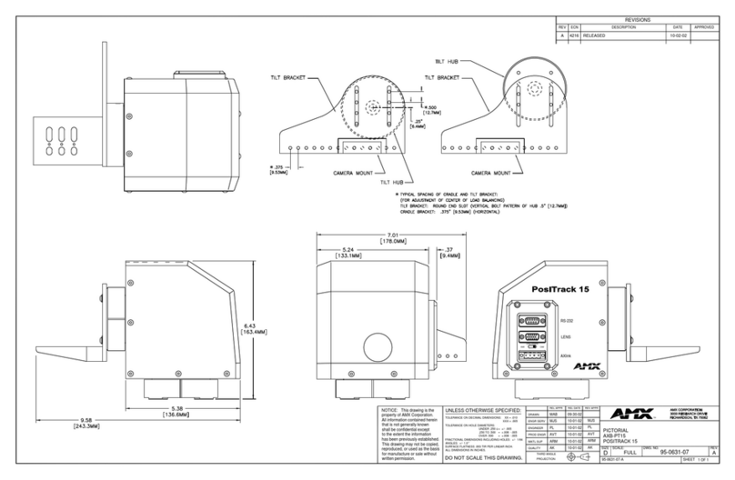
The following drawings are of different perspectives of the PTE-300,for purposes of assisting with
installation questions.
FIG. 3 shows the front of the PTE-300, including the camera control and lens control connectors, the
Ethernet and power connector ports and LEDs, and the camera mount as installed and balanced.
FIG. 4 shows the back of the PTE-300, giving measurements and a view of the camera mount and tilt
axis.
FIG. 3 PTE-300 Front View
FIG. 4 PTE-300 Back View

PTE-300 Pan/Tilt Ethernet Camera Control Head
5
PTE-300 PosiTrack Ethernet Camera Controller
FIG. 5 shows the left side of the PTE-300, showing the main access hole (see the Joyswitch or Local
Control section on page 7).
FIG. 6 shows the PTE-300’s camera mount and its relationship to the device’s tilt hub.
FIG. 5 PTE-300 Left View
FIG. 6 PTE-300 Camera Mount and Tilt Hub

PTE-300 Pan/Tilt Ethernet Camera Control Head
6PTE-300 PosiTrack Ethernet Camera Controller
FIG. 7 provides a top view of the PTE-300, with the front of the unit appearing at the top of the diagram.
FIG. 7 PTE-300 Top View (with attached camera mount)

Pre-Installation
7
PTE-300 PosiTrack Ethernet Camera Controller
Pre-Installation
Overview
The following tools are necessary for installation of the PTE-300:
Joyswitch or Local Control
The PTE-300 uses a lens control "joyswitch," accessible through the main access hole in the back of the
device (FIG. 8), which allows the installer to control pan, tilt, zoom, and focus locally. This way, when
an installer is connecting wiring in an inaccessible or possibly hazardous location, such as atop a ladder,
the installer does not need to leave the site and go to the control room to see if the connections are
correct.
The lens control joyswitch (FIG. 9) contains 5 switches. Moving it left and right relative to the top of the
device controls pan; moving it up and down controls tilt. Pressing in the center of the switch puts the
joyswitch in lens control mode, where moving the joyswitch left and right adjusts zoom, and moving the
joyswitch up and down adjusts focus. Pressing in the center switch again puts it back into pan/tilt control
mode. The PTE-300 will automatically exit local control mode if the joyswitch is not used for 10
seconds. When the PTE-300 is being controlled locally via the joyswitch, communications from the
Netlinx master are ignored.
Necessary Tools
3/32 HEX KEY Camera Alignment Peg
3/16 HEX KEY Camera Mount Screw
5/64 HEX KEY Tilt Arm Screws
3/32 HEX KEY Camera Mount ADJ. Screws
FIG. 8 Location of Joyswitch Access Hole
FIG. 9 Lens control joyswitch (main access hole)
Main Access Hole
LED1
Joyswitch
LED

Pre-Installation
8PTE-300 PosiTrack Ethernet Camera Controller
The LED below and to the right of the joyswitch, LED1, may give one of several signals for the operator:
RS-232 communications settings
The factory default RS-232 communications settings are:
9600 baud
No Parity
8 bits
1 stop bit
The PTE-300 contains one EIA RS-232C standard port for equipment that requires RS-232 control. The
following communication protocols are supported:
300, 2400, 9600, 19200, and 38400 baud
7, 8, or 9 Data bits
1 or 2 Stop bits
Even, Odd, and None parity settings
RS-232 Port DB-9 pinouts
The following table lists the RS-232 Port DB-9 (male) pinouts (FIG. 10).
LED1 Signals
Flashes Status
Once per second Normal operation: Network control mode
Twice per second Normal operation: Local mode
Once every 4 seconds Issue: Firmware not uploaded, and only boot firmware installed.
FIG. 10 RS-232 Port DB-9 (male) pinouts
RS-232 Port DB-9 (male) Pinouts
Pin Signal
1N/A
2 RXD - Receive Data Input
3 TXD - Transmit Data Output
4N/A
5 GND - Ground
6N/A
7 RTS - Ready To Send Output
8 CTS - Clear To Send Input
9N/A
9
8
7
6
5
4
3
2
1
9
8
7
6
Female Male

Installation
9
PTE-300 PosiTrack Ethernet Camera Controller
Installation
Overview
This PTE-300 enables pan and tilt functionality for mounted camera/lens assemblies and provides lens
control functions for teleconferencing lenses. Software-adjustable stop limits are used on the pan and tilt
drives to limit the range of motion.
Mounting the PTE-300
Mount the PTE-300 to a flat horizontal surface, either upright or inverted.
1. Select a surface that can support the combined weight of the PTE-300, the camera/lens, and control
cables and mounting accessories (including the WM-CAM, PM-CAM, and TM-CAM mounts).
2. Locate the external white position markers located on the pan and tilt axis (FIG. 11). The position
markers must align with the pan and tilt axis in order to be considered in the home position.
Do not mount a PTE-300 in any location where the motion of the camera/lens is
obstructed by any object. Impact or connection with obstructions could damage
internal components.
FIG. 11 Center position for the camera cradle attachment
Central tilt-axis
Camera cradle
mounting holes
Camera points this way
Position markers, located on the
outer surfaces, mark the center for
the vertical range of camera motion
Pan hub (mounting plate)
Tilt
H
u
b

Installation
10 PTE-300 PosiTrack Ethernet Camera Controller
3. Mount the PTE-300 to a flat surface by drilling four holes, based on the mounting-plate dimensions
shown in FIG. 12. Secure the unit to the surface using four 1/4” x 20 machine bolts and lock
washers.
The PTE-300 can be mounted to camera mounts such as the TM-CAM (Tripod Mount Adapter),
WM-CAM (Wall Mounting Bracket), and PM-CAM (Flush/Ceiling PosiTrack Pedestal Mount)..
FIG. 12 Pan Hub (Mounting plate) dimensions
3.45"
(87.7mm)
Camera points this way when the pan drive is in
the center of its range of motion (Home position)
Position marker
(on the outer surface)
Ø 3.45"
87.7 mm
3.00 BHC”
76.20 mm
Ensure that the external white position marker, on the pan drive hub, is inside the
desired camera rotation range.
FIG. 13 PTE-300 cradle support bracket
The camera/lens cradle can be mounted on either side of the cradle support bracket.

Installation
11
PTE-300 PosiTrack Ethernet Camera Controller
Camera/Lens Mounting and Balancing
The camera/lens assembly should be mounted so the tilt axis is capable of going through the optical axis
of the camera, assuming the optical centerline is between 1/2” (12.70 mm) and 5" (127.00 mm) above
the mounting plane of the camera lens. The mounting platform (camera cradle) allows the camera/lens to
be mounted with its center of gravity on the tilt axis. The maximum weight of the camera/lens
assemblies on the PTE-300 is 30 lbs. (13.6 kg). The camera cradle is mounted to the Tilt Hub (FIG. 14).
To mount and balance the camera/lens:
1. Separate the camera mount and the cradle support bracket by removing the two 1/2” screws on the
underside of the assembly (see FIG. 15) using a 3/32” Allen wrench.
2. Install the camera alignment peg to the mount at the position that best fits the camera/lens.
3. Secure the camera/lens to the mount (at the camera alignment peg) with the 1/2” screw and
1/10” thick washer supplied (see FIG. 15).
FIG. 14 Tilt Hub dimensions for the PTE-300
0.750"
19.05 mm
0.750"
19.05 mm
0.750"
19.05 mm
0.750"
19.05 mm
0.250"
6.35 mm
0.00"
0.00"
Position
markers
Camera points
in this direction
1.50"
38.1 mm
0.250"
6.35 mm
Do not lift the PTE-300 by the Camera/Lens cradle, as this could damage internal
components.
FIG. 15 Camera bracket assembly
Mounting holes (three sets) Cradle support brack
e
Camera alignment peg
Camera/Lens cradle
assembly (side view)
Camera mount
(underside view)

Installation
12 PTE-300 PosiTrack Ethernet Camera Controller
4. Place the assembly on a balancing beam and, while maintaining the cradle centered on the pipe,
slide the camera along the cradle’s grooves until the camera and cradle remain balanced on the
beam (see FIG. 16). Verify the balance with a spirit level.
5. Mount the camera as close to the Tilt Hub as possible to obtain a true center of gravity. The center of
gravity is the location on the long axis of the camera/lens assembly around which the camera and
mount balances.
6. Re-attach the camera mount (with camera/lens) to the cradle support bracket using the two 1/2”
screws.
7. Take the entire camera/mount and cradle assembly and align the lens with the Tilt Hub so that the
vertical axis intersects the center of the camera’s iris, as shown in FIG. 17.
8. Mark the position of the cradle support bracket on the Tilt Hub (for later attachment).
9. Remove the camera/lens and mount piece from the support bracket by unscrewing the two 1/2”
screws on the underside of the camera mount.
10. Secure the support bracket to the Tilt Hub (at the same position marked for the iris alignment) on the
PTE-300 with some or all of the four 1/2” screws and washers.
11. Secure the camera/mount to the support bracket by using the two 1/2” screws.
12. Support the weight of the camera cables with a wire tie attached to the wire tie mount on the lower
corner of the face of the PTE-300 (FIG. 13).
FIG. 16 Balancing the camera/lens cradle assembly
FIG. 17 Iris alignment with vertical tilt-axis
cradle
(bottom view) balancing beam
Marker points
Iris
Vertical tilt-axis
The camera/lens cradle can be mounted on either side of the cradle support bracket.

Installation
13
PTE-300 PosiTrack Ethernet Camera Controller
Installing the PTE-300 on an WM-CAM Wall Mount Bracket
Flat Surface
1. Mount the PTE-300 to a flat surface by drilling four holes, according to the mounting-plate
dimensions shown in FIG. 18.
2. Secure the unit to the surface using four 1/4" x 20 machine bolts and lock washers. Ensure that the
external white position marker, on the pan drive hub, is inside the desired camera rotation range.
FIG. 18 Pan Hub (Mounting plate) dimensions (underside of PTE-300 units)
3.45"
(87.7mm)
Camera points this way when the
pan drive is in the center of its
range of motion
(Mechanical home position)
Position marker
(on the outer surface)
Ø 3.45"
(87.7 mm) 3.00 BHC"
(76.20 mm)

Installation
14 PTE-300 PosiTrack Ethernet Camera Controller
Wall Surface
1. Mount the PTE-300 to a wall surface with the optional WM-CAM by drilling six holes according to
the mounting dimensions shown in FIG. 19.
FIG. 19 WM-CAM mounting plate dimensions (front view)

Installation
15
PTE-300 PosiTrack Ethernet Camera Controller
2. Once the WM-CAM (PosiTrack version) is securely attached to the wall; secure the PosiTrack unit
to the WM-CAM’s mounting plate using four 1/2” (1/4” x 20) machine bolts and lock washers.
FIG. 20 shows a side view of the WM-CAM.
3. Once the PosiTrack unit is securely attached to the WM-CAM, mount and balance the camera/lens
on the PosiTrack unit. Refer to the Camera/Lens Mounting and Balancing section on page 11 for
details.
FIG. 20 WM-CAM mounting plate dimensions (side view)
.265 DIA THRU HOLE
ACCEPTS PTE-300 BASE
1.75"
(44.45 MM.)
18.00"
(457.2 MM.)
5.473
(139.0 MM)

Installation
16 PTE-300 PosiTrack Ethernet Camera Controller
Connections and Wiring
Wiring the Connectors
The PTE-300 has an RS-232 DB-9 connector, lens control HD-15 high-density connector, 2-pin captive-
screw power connector, and an Ethernet RJ-45 connector.
The PTE-300 receives all power from the 24VDC and GND connections on the 2-pin power
connector (refer to the Power Connector section on page 18 for details).
FIG. 1 on page 1 shows the location of the connectors on the PTE-300.
To prevent excessive bending at the connector, attach the Ethernet cable to the Relief Anchor at the
bottom left corner of the PTE-300 (FIG. 21).
Camera Control (RS-232 DB-9) Port
The RS-232 DB-9 (male) connector on the PTE-300 connects to the camera head’s RS-232 connector.
The following table shows the (DB-9) RS-232 connector wiring diagram.
Always provide enough cable to accommodate the desired range of motion for the
PTE-300 and its camera and lenses. Making a service loop in the cable adequate for
the full range of motion of the camera is highly recommended.
FIG. 21 PTE-300 Relief Anchor
(DB-9) RS-232 Connector Pinouts
Pin Signal Function
1 N/A Not used
2 RXD Receive data
3 TXD Transmit data
4 DTR Data terminal ready (not
used)
5 GND Signal ground
6 DSR Data set ready (not used)
7 RTS Request to send (output)
8 CTS Clear to send (input)
9 N/A Not used
Relief
Anchor
9
8
7
6
5
4
3
2
1
9
8
7
6
Female Male
Other manuals for PTE-300
2
Table of contents
Other AMX Camera Accessories manuals