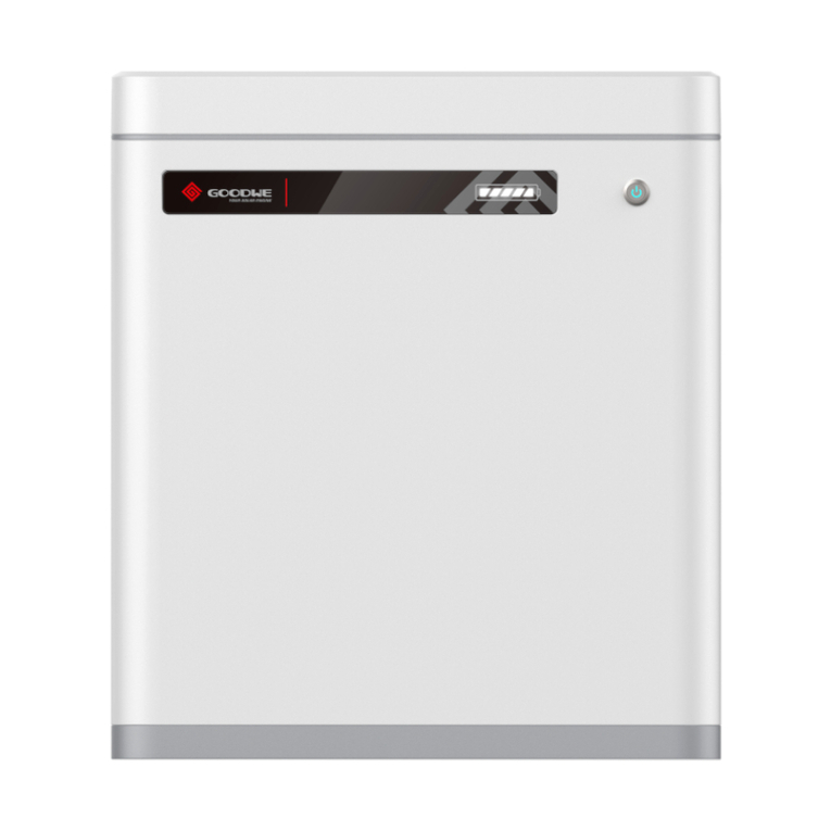
Goodwe Lynx Home U Series User manual

Lynx Home U Series (LV)
User Manual
Ver 1.0
2021-3-30

• AlltheinformationinthisdocumentisthepropertyofGoodWe.Nopartofthisdocumentcould
bereproducedinanywayforbusinessuse.Internaluseisallowed.
• GoodWe makes no representations or warranties express or implied, with respect to this
documentoranyoftheequipmentand/orsoftwareitmaydescribe,including(withnolimitation)
anyimpliedwarrantiesofutility,merchantability,ortnessforanyparticularpurpose.Allsuch
representations or warranties are expressly disclaimed. Neither GoodWe nor its distributors
or dealers shall be liable for any indirect, incidental, or consequential damages under any
circumstances.
• Theexclusionofimpliedwarrantiesmaynotapplyinallcasesundersomestatutes,andthusthe
aboveexclusionmaynotapply.
• Specicationsaresubjecttochangewithoutnotice.Everyeorthasbeenmadetomakethis
document complete, accurate, and up-to-date. However, GoodWe may need to make some
improvements under certain circumstances without advance notice. GoodWe shall not be
responsibleforanylosscausedbythisdocumentincluding,butnotlimitedtoomissionserrors,
typographicalerrors,arithmeticalerrors,orlistingerrorsinthisdocument.
Disclaimer
Version Date Record
V1.0 2021-3-30 FirstRelease
GOODWEwillnotbeliableforanyconsequenceslikebatterydamageorpropertylossunderthe
followingcircumstances:
• Modify,alter,orreplacepartsofthesystemwithoutauthorizationfromGOODWE
• AnyoneexcepttechniciansfromGOODWEchangesorerasetheserialnumber.
• Establishasystemthatdoesnotmeetthecriteria,safetyregulations,andotherrelated
requirements.
• Non-observancetotheUserManual.
• Improperuseormisuseofthebattery.
• Inadequateventilation.
• Themaintenanceroutinedoesnotfollowacceptedstandards.
• ForceMajeurelikeearthquakes,storms,thunders,overvoltage,orrehazards,etc.
• Anyexternalfactors.
Limitation of Liability

TABLE OF CONTENTS
01 Safety Precaution ................................................................ 1
02 Product Introduction ........................................................... 2
2.1ProductDescription........................................................................................2
2.2SymbolDescription.........................................................................................2
03 Battery Introduction ............................................................ 3
3.1Appearance......................................................................................................3
3.2Dimensions......................................................................................................4
04 Storage and Package ............................................................ 5
4.1StorageEnvironment......................................................................................5
4.2PackingList......................................................................................................5
05 System Installation .............................................................. 6
5.1InstallationEnvironment................................................................................6
5.2MountingSpaceRequirements......................................................................6
5.2.1FloorMountingSpaceRequirements..................................................................... 6
5.2.2WallMountingSpaceRequirements...................................................................... 7
5.3SystemInstallation..........................................................................................8
5.3.1PackageRemoving................................................................................................... 8
5.3.2FloorMounting......................................................................................................... 9
5.3.3WallMounting.......................................................................................................... 9
5.3.4CableConnection.................................................................................................. 10
5.3.5InstalltheWireHarnessFixBar............................................................................ 14
06 System Operation .............................................................. 15
6.1CheckBeforePowerOn...............................................................................15
6.2PowerOn.......................................................................................................15
6.3BatteryParameterSettings..........................................................................15
6.4IndicatorStatus............................................................................................16
6.4.1NormalState.......................................................................................................... 16
6.4.2Alerting................................................................................................................... 17
6.4.3Faulty...................................................................................................................... 17
6.5PowerO.......................................................................................................18
6.6InstallthePlasticCover................................................................................18
07 Technical Parameters ......................................................... 19
08 Maintenance ...................................................................... 20
RemovethePlasticCover............................................................................................... 20

1
01 Safety Precaution
• PleasekeepPowerObeforeanyoperationstoavoiddanger.Strictlyfollowallsafetyprecautions
outlinedinthismanualandsafetylabelsontheequipment.
• Allinstallationoperationsshouldbeperformedbytrainedandknowledgeabletechnicalpersonnel
whoarefamiliarwithlocalstandardsandelectricsystems.
• Donotusethebatteryifitisdefective,broken,ordamaged.
• Do not disassemble, modify, or replace any part of the battery without ocial authorization from
GoodWe.
• Damagedbatterymayleakelectrolyte.Donotcontactwiththeliquidleakageorvolatilematter.Please
contactGoodWeTechnicalSupportforhelpimmediately.
• Transportation:
• Protectthebatteriesandtheircomponentsfromdamageduringtransportationandstorage.
• Taketheweightofthebatteryintoaccountandcarefullyliftthebatteries.
• Donothit,pull,drag,orsteponthebatteriesorputunrelateditemsintoanypartofthebatteries.
• Thetransportationmustbecarriedoutbytrainedprofessionals.Alloperationsduringtheprocesshave
toberecorded.
• Keeptheequipmentstabletoavoiddumping,whichcanresultinequipmentdamageandpersonal
injuries.
• Intheeventofare,pleasemakesurethatthecarbondioxideextinguisherorNovac1230orFM-200is
nearby.Therecannotbeputoutbywater(ABCdoesnotworkforbatteryre-ghting).
• Fireghtersarerequiredtowearfullprotectiveclothingandself-containedbreathingapparatuswhen
ghtingres.
• Thebatterymayexplodewhentheambienttemperatureexceeds150℃.
• Please use appropriate tools and take protective measures when installing and maintaining heavy
equipment.Improperoperationswillcausepersonalinjuries.
• Placethecablesatleast30mmawayfromtheheatingcomponentsorheatsources,otherwise
theinsulationlayerofthecablesmaybeagingorbrokenduetothehightemperature.
• Tiethecablesofthesametypetogether,andplacecablesofdierenttypesatleast30mmapart.Do
notplacethecablesentangledorcrossed.
• Anyonecontacttheleakedsubstanceaccidentlyhastodoasfollowing:
• Breathintheleakedsubstance:Evacuatefromthepollutedarea,andseekimmediatemedical
assistance.
• Eyecontact:Rinseyoureyesforatleast15minuteswithcleanwaterandseekimmediatemedical
assistance.
• Skincontact:Thoroughlywashthetouchareawithsoapandcleanwater,andseekimmediate
medicalassistance.
• Ingestion:Inducevomiting,andseekimmediatemedicalassistance.
• Do not move the battery system if it is connected with external battery expansion modules.
PleasecontactAfter-salesServicetoreplacebatteriesoraddbatteries.
DANGER!
WARNING!
CAUTION!

2
• ThismanualintroducesLynxHomeUSeries(LV)BatterySystem(hereinafterreferredtoasthe
BatterySystem),includingtheproductintroduction,application,installation,commission,and
technicalparameters,etc.
• TheBatterySystemcanmatchwithGOODWEES、EM、SBP、BPseriesinverters.
• Atmost6batteriescanbeconnectedinthisBatterySystem.
02 Product Introduction
2.2 Symbol Description
2.1 Product Description
Symbol Description
A potential hazard exists when the equipment is
working. Wear personal protective equipment
during operation.
High voltage danger. Power o the equipment
before any operations.
Operate the equipment properly to avoid
explosion danger.
The battery contains corrosive electrolytes. Please
avoid contact with leaked liquid or gas.
Refer to all manuals before any operations.
Pay attention to safety protection during
installation, operation, and maintenance.
Keep the battery away from open ame or
ignition sources.
Keep the battery away from children.
Put the battery in the right place and recycle it in
compliance with local environmental regulations.
Recycle the equipment following local
environment regulations.
CE Mark
RCM Mark
Grounding. To indicate PE cable connection
position.
Li -Io n

3
03 Battery Introduction
No. Parts Description
1 SOCIndicator Remainingpowerdisplay;indicatesthebattery
statetogetherwiththebuttonindicator.
2 SwitchButton Switchon/othebattery
3 ButtonIndicator Greenandredlight;indicatesthebatterystate
togetherwiththeSOCindicator
4 GroundingTeminal GroundingProtection
5 NegativePoleoftheBattery Powertransmission
6 PositivePoleoftheBattery Powertransmission
7 CANCOMPort Communicationtransmission
8 Circuit-Breaker Shortcircuit/breakprotection
3.1 Appearance
12
3
44 5 6 6 57 7 8

4
3.2 Dimensions
570mm
285mm
505mm
124mm 124mm
175mm
Wall Mounting Plate
FrontView SideView

5
04 Storage and Package
4.1 Storage Environment
4.2 Packing List
Iftheequipmentisnottobeinstalledorusedimmediately,pleaseensurethatthestorage
environmentmeetsthefollowingrequirements:
• Packtheequipmentusingapackingboxandputsomedesiccantintheboxbeforesealing.
• Puttheequipmentbacktothepackingboxifitisnottobeinstalledin3daysafterunpacking.
• StorageSOC:25%~50%SOC.Chargeanddischargethebatteryevery3months.
• Recommendedstoragetemperature:-20℃~40℃(lessthanonemonth)or0℃~35℃(lessthan
oneyear).
• Recommendedstoragehumidity:0%~95%RH(nocondensation).Donotinstallthebatteryifany
moistorcondensationisfound.
• Placethequipmentinacoolplacewhereawayfromdirectsunlight.
• Keeptheequipmentawayfrominammable,explosive,andcorrosivematters.
• Keeptheequipmentawayfromtherain.
• Checkouterpackingfordamageandmodelbeforeunpackingit.Ifyoundanydamageorthe
modelisnotwhatyourequested,donotunpacktheproductandcontacttheafter-salesservice
assoonaspossible.
• Checkwhetherthedeliverablesareintactandcompleterstafterunpackingthebattery.If
anythingwrong,contacttheafter-salesserviceassoonaspossible.
Battery x 1 Plastic Cover x1
Wall Mounting
Plate x 1
Anti-dumping
Bracket x 2
Wire Harness Fix
Barx2
Red Power
Connector x 2
Black Power
Connctor x 2
Terminal
Resistance x 1
Grounding
Terminal x 4
M5 Assembling
Bolt x 8
M10 Expansion
Bolt x 6
Assembling
Expanshion Bolt x 2
N/A N/A N/A

6
05 System Installation
5.1 Installation Environment
5.2 Mounting Space Requirements
• InstalltheBatterySystemonthegroundwithsucientbearingcapacityandatness.Increase
thebearingcapacityandatnessofthegroundbylayingthefoundation,addingbearingplates
andsoon.
• Theoptimaltemperatureforthebatteryis20~40℃.
• Avoidexposingtheequipmenttodirectsunlightorrain.
• Installtheequipmentawayfromheat/coldsource.
• Donotinstalltheequipmentintheplacewherethetemperaturechangesextremely.
• Installtheequipmentawayfromstronginterferencestoensureitsregularwork.
• Keepchildrenawayfromtheequipment.
• Donotinstalltheequipmentinplacespronetoaccumulatewater.
• Donotputinammableorexplosivemattersneartheequipment.
5.2.1 Floor Mounting Space Requirements
≥200mm
≥300mm ≥300mm
≥300mm
The space between the left and the right battery is a recommened distance.
Keep the distance as short as you can if there is no inuence to the
operation.

7
5.2.2 Wall Mounting Space Requirements
The space between the left and the right battery is a recommened distance.
Keep the distance as short as you can if there is no inuence to the
operation.
Single Row Installation
Double Row Installation
300~500mm
≥300mm
≥500mm
BAT 1 BAT 2 BAT 6
......
≥500mm
≥300mm
≤1500mm
≥200mm
≥300mm
≥500mm
≥300mm
≥500mm
300~500mm 300~500mm
BAT 1 BAT 2
BAT 4 BAT 5 BAT 6
BAT 3
≤1500mm

8
5.3 System Installation
1.Unpackthecartonandtaketheaccessorybagout.
2.Pullthecartonupwardstoremoveit.
3.Takeoutthewallmountingplate.
4.Holdthebatteryhandletotakethebatteryout.
5.3.1 Package Removing
• Ifmultibatteriesaretobeconnected,checkandselectbatterieswith
similarproductiondate.
• Strictlyfollowthewarningsontheouterpackage,whichshowsyouthe
rightdirectionforplacing.

9
5.3.2 Floor Mounting
Makesurethattheoorisatandhorizontal.Installtheanti-dumping
bracketonbothsides.
1.Screwtheanti-dumpingbrackeonthebattery.
2.Alignthebatteryandthewall,thenputtheanti-dumpingbracketclosetothewall.Markthe
drillingpositionandremovethebattery.
3.Drillaholeonthewallusingthedriller.Holediameter10mmanddepth80mm.
4.Fixtheexpansionbolts,tighteningtorque:10N·m.
5.3.3 Wall Mounting
1.Markthedrillingpositionusingthewallmountingplateandlevelusingaspiritlevel.
2.Placethewallmountingplateclosetothewallrmly,markthedrillingpositionandremovethe
wallmountingplate.
3.Drillaholeonthewallusingthedriller.Holediameter13mmanddepth65mm.
4.FixtheM10expansionbolts,tighteningtorque:10N·m.
Wallmountingneedstobedonebytwopersons.
Ifthebubbleofthe
spiritleveliswithinthe
dashedlines,thenthe
plateishorizontal.
2 N·M
M5

10
5.3.4 Cable Connection
4.Liftthebatteryparalleltotheground.
5.Hangtheupperpartofthebatteryonthewallmountingplate.
6.Pushthebottompartofthebatterytotheslot.
Overview of the cable connection
1
2
Ground
Cable
Standard
NetCable
PowerCable
forNegative
Pole
PowerCable
forPositive
Pole
TakeSBPseriesasanexamplehere.
......
COM PORT COM PORTCOM PORT COM PORT
Terminal Resistance
Battery 1 Battery 2 Battery 6
Wi-Fi
Reset/Reload
SYSTEM
GRID
BACK-UP
ENERGY
COM
Wi-Fi
BATTERY
FAULT
2019

11
Ground Cable Connection
1.Crimpthegroundterminal.
2.Connectthegroundcabletothebattery.
• ConnectthePEcablerstbeforeinstallingtheequipment.Disconnectthe
PEcablebeforedismantlingtheequipment.
• Thedrawingforceofthecablesaftercrimpingisatleast400N.
• Connectanyoneofthetwogroundcablestotheground.Reservethe
othergroundcable.
• Thecross-sectionalareaofthePEcableconductor:5mm2.Thecable
shouldmeetstandardsforoutdooruse.
2 N·M
M5
L2=L1+(1~2)mm
L2
L1

12
Power Cable Connection
1. Crimpthepowercable.
2. Puttherubbersealring.
3. Securethebackshell.
• Connecttheredpowercabletotheredwireharness,andtheblackpower
cabletotheblackwireharness.Thecross-sectionalareaofthecrimpingpartis
25mm².
• WithstandVoltage:DC1500V;Temperature:-40℃~200℃.
• Strippedconductorlength:18±1mm.
• Securethebackshellandcheckwhetherthereisanygap.
• Recommendedtool:manualhydraulicpressplier(mould:25mm²)
• Drawingforceaftercrimping≥1200N.
• Ifasinglebatteryisapplied,youaresuggestedtoconnectanyoneofthetwo
powerportsandcovertheotherportusingtheprotectivecover.
• Connectpowercablesbetweenmultibatteriesinparallel,whichmeans
connectpostivepoleofonebatterytothepositivepoleofthenextbattery,
andnegativepoletonegativepole.Coverandprotectthereservedpower
portofthelastbattery.
• Thepowercablebetweenthebatteriesshouldbeasshortasitcanbeandmeet
installationrequirements.
Length:7.5±0.2mm
Height:7.5±0.2mm
4.Connectthepowercable.
1
2
3
Click

13
Communication Cable Connection
1.Removethewaterproofmodule.
Thetwocommunicationcablesarethesame.
• DonotuseRJ45cablewithprotectivecover.
• Whenonebatteryisapplied,connectonecommunicationcabletothe
inverterbyRJ45connectorandconnecttheothercabletotheterminal
resistance.
• Whenmultiplebatteriesareapplied,connectthecommunicationports
inseriesusingnetcables.Connectonecommunicationcableofthelast
batterytotheterminalresistance.
RJ45 Registered Jack
CAN COM Port
PIN Denition
4 CAN_H
5 CAN_L
1,2,3,6,7,8 N/A
2.Routethecablethroughthewaterproofmodule.
3.CrimptheRJ45RegisteredJack.
4.Securethebackcover.
12345678
1
2
3

14
5.Connectthecommunicationcableandtheterminalresistancetothebattery.
6.Securethecover.
1.Putthewireharnessonthecorrespondingslot.
2.InstallthebarusingM5screws.
5.3.5 Install the Wire Harness Fix Bar
2 N·M
M5

15
06 System Operation
SelecttherightoptionsonPVMasterafterconnectingthebatteryandtheinverter.
Select“LXU5.4-L”onPVMaster.
"BatterySelectionAbnormal"willbedisplayedifyouselectthewrong
batterymodel.Pleaseselecttherightbatterymodelaccordingly.
APPInstallatinandConnection:
SelectthebatterymodelonPVMaster:
6.2 Power On
6.3 Battery Parameter Settings
Download
andInstall
PVMaster
Connectthesmartphone
withtheinverter.
Wi-FiSSID:Solar-WiFi**
Passwaord:12345678
LXU5.4-L*1
LXU5.4-L*2
LXU5.4-L*3
LXU5.4-L*4
LXU5.4-L*5
LXU5.4-L*6
6.1 Check Before Power On
No. Items
1The equipment is installed rmly in a place where is convenient for operation and
maintenance. The installation place is clean and well ventilated.
2The ground cable, power cable, communication cable and terminal resistance are
connected correctly and securely.
3The cable ties meet the cabling requirements and are reasonably distributed. No
cables or ties are broken.
4 Unused ports are sealed.
Checkthefollowingitemsbeforepoweron.Otherwise,theBatterySystemmaybedamaged.
1. TurnontheCircuit-Breaker.
2. Presstheswitchbuttonofallbatteriesin30s,otherwisetheequipmentwillstartalarming.

16
6.4 Indicator Status
Button Indicator Status
GreenLight Standby、Working、Alert
RedLight Faulty
Button Indicator SOC Indicator Description
Standby:greenlight
blinkingfor1s
Working:greenlighton
SOC<5%
5%≤SOC<25%
25%≤SOC<50%
50%≤SOC<75%
75%≤SOC<95%
SOC≥95%
SOCIndicator ButtonIndicator
6.4.1 Normal State

17
Button
Indicator SOC Indicator Alerting Solutions
Greenlight
blingkingfor3s
Temperature
Exception Poweroandrestartafter2hours.Ifthe
problempersists,pleasecontactGoodWe.
HighTemperature
LowTemperature
Discharging
PoweroandWaitforthetemperatureto
increase.Restartthebattery.Iftheproblem
persists,pleasecontactGoodWe.
Overcurrentwhen
Charging
Restartthebattery.Iftheproblempersists,
pleasecontactGoodWe.
OvercurrentWhen
Discharging
Overvoltage
Undervoltage Pressthebuttonconsecutivelyfor5times
in10sifyoucanchargethebattery.The
voltagewillrecovertonormal.
LowTemperature
Charging
PoweroandWaitforthetemperatureto
increase.Restartthebattery.Iftheproblem
persists,pleasecontactGoodWe.
• Restartthebatterybypressingtheswitchbutton.
• Ifthebatteriespowerounderundervoltageprotectionandmultiple
batteriesareconnected,justpressthebuttonofanyonebattery
consecutivelyfor5timestoactivatethem.
Button
Indicator SOC Indicator Fault Solution
Redlight
blinkingfor3s
Temp.sensor
failure Restartthebattery.Iftheproblempersists,
pleasecontactGoodWeforhelp.
MOSFailure
Circuit-Breaker
Failure TurnontheCircuit-Breaker.Iftheproblem
persists,pleasecontactGoodWe.
SlaverControl
Communication
Lost
Poweroandcheckthecommunication
cable.Restartthebattery.Iftheproblem
persists,pleasecontactGoodWe.
SNFailure ContactGoodWeforhelp.
MasterControl
Communication
Lost
Poweroandcheckthecommunication
cable.Restartthebattery.Iftheproblem
persists,pleasecontactGoodWe.
Inconsistent
SoftwareVersion ContactGoodWeforhelp.
MultiMaster
ControlFailure Startallbatteriesin30saftershutting
down.
MOS
Overtemperature Powerofor2hours.Iftheproblem
persists,pleasecontactGoodWe.
Communication
Failure
Poweroandcheckthecommunication
cable.Restartthebattery.Iftheproblem
persists,pleasecontactGoodWe.
6.4.2 Alerting
6.4.3 Faulty
Other manuals for Lynx Home U Series
3
This manual suits for next models
1
Table of contents
Other Goodwe Camera Accessories manuals

Goodwe
Goodwe Lynx C Series User manual

Goodwe
Goodwe Lynx Home S Series User manual

Goodwe
Goodwe SECU-A Series User manual

Goodwe
Goodwe Lynx Home FH US Series User manual

Goodwe
Goodwe Lynx C Series User manual

Goodwe
Goodwe Lynx C Series User manual

Goodwe
Goodwe Lynx Home U Series User manual

Goodwe
Goodwe Lynx Home F Plus+ Series User manual

Goodwe
Goodwe Lynx C Series User manual

Goodwe
Goodwe ET Series User manual