manuals.online logo
Brands
  1. Home
  2. •
  3. Brands
  4. •
  5. MuxLab
  6. •
  7. Transmitter
  8. •
  9. MuxLab 500053-WP-UK User manual

MuxLab 500053-WP-UK User manual

© MuxLab Inc. 2010 94-000679-A SE-000679-A
8495 Dalton Road, Mount Royal, Quebec, Canada. H4T 1V5
Tel: (514) 905-0588 Fax: (514) 905-0589
Toll Free (North America): (877) 689-5228
E-mail: v[email protected] URL: www.muxlab.com
Specifications
Environment Component Video (YPbPr), RGB Video (sync on green). 480i/p, 720p,
1080i/p. Line level analog audio.
Devices DVD players, satellite receivers, plasma displays, projectors, monitors,
up-converters, amplifiers, switchers, home theatre and other equipment
supporting HDTV component video and/or analog audio.
Transmission Transparent to the user
Bandwidth Video: 60 MHz, 3 dB roll off
Analog audio: 20 Hz to 20 kHz
Maximum Input 1.1 Vp-p
Insertion Loss per Pair
(Video)
0.1 dB for 0.1 MHz
Gradually increasing to 3.0 dB over the frequency range
Insertion Loss per Pair
(Audio)
Less than 2 dB per pair over the frequency range
Return Loss (Video) Greater than 15 dB over the frequency range
Common Mode Rejection
Ratio (Video)
-55 dB max.
Common Mode Rejection
Ratio (Audio)
Greater than 60 dB at 1 kHz
Greater than 40 dB over the frequency and distance range
Max. Distance Color via
Cat 5E/6 UTP/STP Cable
480i/p: 1,000 ft (305 m)
720p and 1080i: 500 ft (152 m)
Analog Audio: 3,250 ft (990 m)
Cable:
Cat 5E/6 UTP/STP
24 AWG or lower solid copper twisted pair wire
Impedance: 100 ohms at 1 MHz
Maximum capacitance: 20 pf/ft
Attenuation: 6.6 dB/1,000 ft at 1 MHz
Cable: Coax Impedance: 75 ohms at 1 MHz
Connectors Three RCA-F connectors: Green (Y), Blue (Pb), Red (Pr)
One (1) RCA-F connector for analog audio
RJ45S for twisted pair
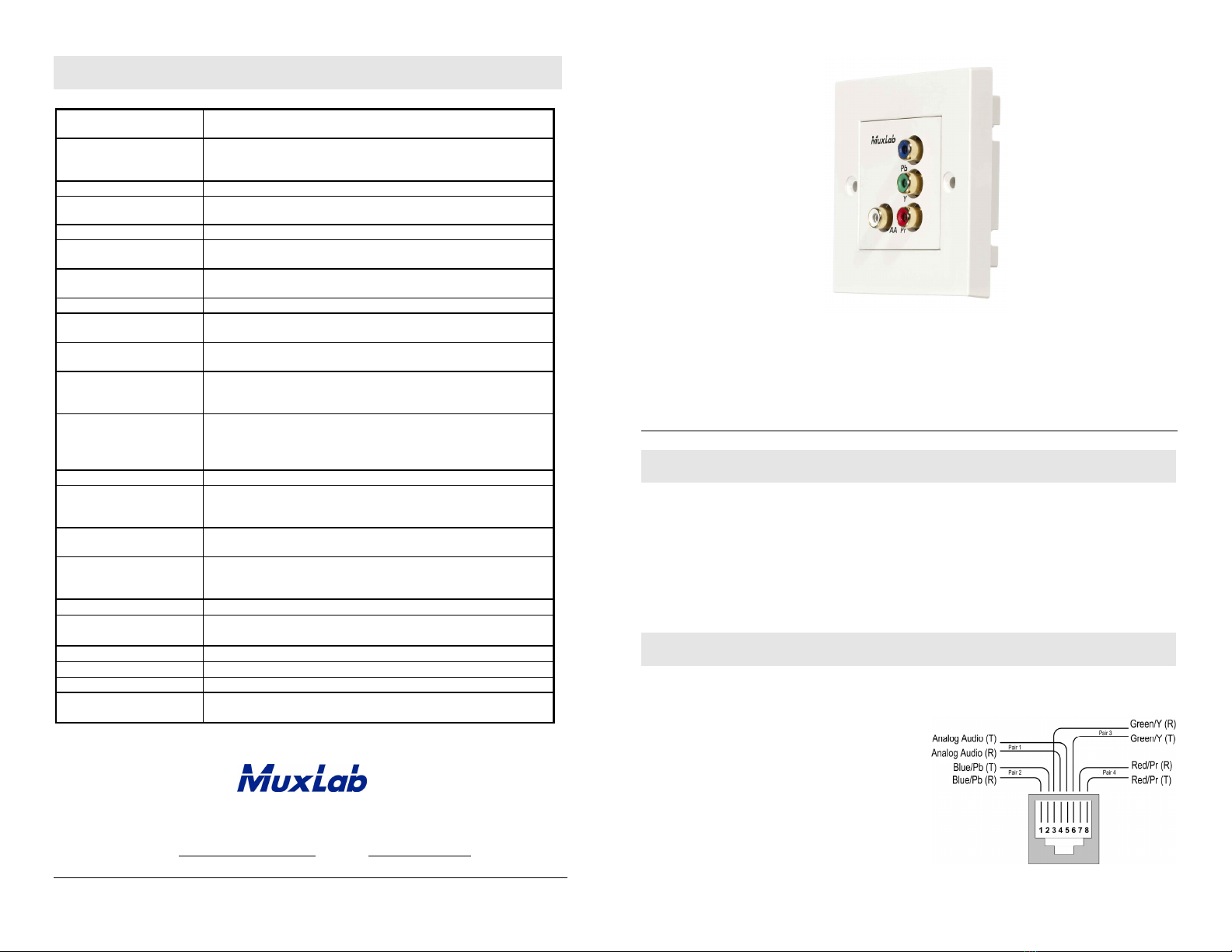
Pin Configuration
Reverse polarity sensitive
Red (Pr): Pins 7(R) & 8(T) Green (Y): Pins 3(R) & 6(T)
Blue (Pb): Pins 1(R) & 2(T) Analog Audio: Pins 4(R) & 5(T)
Temperature Operating: 0° to 55°C
Storage: -20° to 85°C
Humidity: Up to 95% non-condensing
Enclosure
ABS fire retardant plastic, Color white, Finish glossy.
Dimensions
86 mm x 86 mm x 36 mm. Choose 40 mm deep back box to allow
for Cat 5E/6 wiring connection.
Weight
4.1 oz (115 g)
Regulatory
FCC, CE, RoHS, European Standard for 86 mm faceplate
Warranty Lifetime
Order Information 500053-WP-UK Component Video / Analog Audio Wall Balun
UPC: 6-27699-91053-5
Component Video/Analog Audio Wall Balun
500053-WP-UK
Quick Installation Guide
Overview
The Component Video/Analog Audio Wall Balun (500053-WP-UK) allows one component
video (YPbPr or RGB) signal and one Analog Audio signal to be transmitted via a cost-
effective unshielded twisted pair (UTP) cable. Used in pairs, or in conjunction with the
500048 or 500049, the Component Video/Analog Audio Wall Balun supports 480i/p, 720p
and 1080i/p resolution for hi-definition (HDTV) video applications. The product allows four
coaxial cables to be replaced by one Category 5E/6 twisted pair cable allowing standard
structured cabling techniques to be used for more efficient cabling.
Installation
One (1) pair of baluns is needed to complete one component (YPbPr/RGB) connection via
Cat 5E/6 twisted pair. To install the baluns, perform the following steps:
1. Identify the pin configuration of the
baluns. Three (3) twisted pairs are required
for video and one (1) twisted pair is
required for optional analog audio. The pin
configuration follows the EIA/TIA 568A/B
standard. The Component Video/Analog
Audio Balun is reverse polarity sensitive.
Please ensure that wiring is straight-
through (Ring to Ring, Tip to Tip).
© MuxLab Inc. 2010
2. To install the balun in a single back box, choose a back box
with a depth of 40 mm or more. Connect the RJ45 plug into
the rear of the balun. Secure the balun with the 2 front screws.
3. Plug one (1) balun into the component video coaxial cable
output of the video source according to the color code of the
RCA connectors.
4. Plug the second balun into the component video coaxial cable input of the video
screen or receiver at the remote end.
5. Complete the connection between the two baluns, using standard Cat 5E/6 twisted
pair cable and connecting hardware, terminated on RJ45 plugs at both ends. Ensure
that there are no split pairs or taps.
6. If analog audio is to be connected (optional), connect an RCA lead between the
balun and the analog audio equipment at both ends.
7. Power-on the component video equipment. Check the image quality and refer to the
troubleshooting table below if the image quality is unsatisfactory. The following
diagram shows a typical installation.
8. To mount the wall plate balun in a gang plate, you must first remove the rear 4 screws,
then remove the balun. Then unclip the balun front plastic panel.
9. Clip the front plastic panel to a standard gang plate and secure
the balun using its 4 screws. Multiple wall baluns can be
mounted side by side on a gang plate.
Front view Side view Rear view
Troubleshooting
The following tables describe some of the symptoms, probable causes and possible
solutions in respect to the installation of the Component Video/Analog Audio Balun:
Video Symptom Probable Cause Possible Solutions
No continuity in video
link
Verify cable continuity between pairs of
baluns.
Power off Check power supplies of video equipment.No video
Improper connection
and/or swapped pairs
Check that baluns are connected to correct
video inputs and outputs.
Unusual colors Reversed polarity Check wiring and ensure straight-through
polarity.
Background pattern EMI interference
Identify possible radiating frequency sources
(i.e., wireless LANs, switching power
supplies). Try to isolate them from the video
connection. Use shielded twisted pair
grounded at both ends.
Smearing Exceeded distance Verify cable grade. Use higher grade cable if
necessary.
Exceeded distance Verify cable grade. Use higher grade cable if
necessary. Increase contrast on monitor.
Weak contrast
Unusual link attenuation Verify cable distance using ohmmeter or
cable tester.
Image not stable Defective link or
equipment Verify video equipment interface integrity.
Horizontal bars moving
slowly
Substantial crosstalk
between multiple video
sources
Consecutively turn off other video sources
to determine which video source is the cause
of interference.
Snowy picture Distance is near limit
Verify cable grade. Use higher grade cable if
necessary. Reduce color intensity at
monitor.
Audio Symptom Probable Cause Possible Solutions
EMI interference Check that wiring is not too close to
transformers and ballasts.
Poor audio quality
Split pair Ensure that the UTP pairs are not split and
that each pair of wires is twisted.
No power Check your audio system for power.
Open circuit Check wiring to ensure continuity.No audio
Defective balun Change baluns for another pair.
Audio phase cancellation Reversed wires Check for straight-through wiring.
Audio weak Distance specifications
exceeded
Check DC loop resistance and verify if
distance spec is exceeded. Reduce cable
length or eliminate high-loss components.
If you still cannot diagnose the problem, please call MuxLab Customer Technical
Support at 877-689-5228 (toll-free in North America) or (+1) 514-905-0588
(International).

Other MuxLab Transmitter manuals

MuxLab 500052 User manual

MuxLab

MuxLab 500052 User manual

MuxLab 500028-WP-UK User manual

MuxLab

MuxLab 500028-WP-UK User manual

MuxLab 500773-TX User manual

MuxLab

MuxLab 500773-TX User manual

MuxLab 500060 User manual

MuxLab

MuxLab 500060 User manual

MuxLab 500777-TX-DECO User manual

MuxLab

MuxLab 500777-TX-DECO User manual

MuxLab 500016 User manual

MuxLab

MuxLab 500016 User manual

MuxLab 500052-PRO-BNC User manual

MuxLab

MuxLab 500052-PRO-BNC User manual

MuxLab 500764-TX User manual

MuxLab

MuxLab 500764-TX User manual

MuxLab 500755-AMP-TX User manual

MuxLab

MuxLab 500755-AMP-TX User manual

MuxLab 500032 User manual

MuxLab

MuxLab 500032 User manual

MuxLab SE-000857-C User manual

MuxLab

MuxLab SE-000857-C User manual

MuxLab 500056-PRO User manual

MuxLab

MuxLab 500056-PRO User manual

MuxLab 500038-WP-US User manual

MuxLab

MuxLab 500038-WP-US User manual

MuxLab 500058-WP-UK User manual

MuxLab

MuxLab 500058-WP-UK User manual

MuxLab 500763-TX User manual

MuxLab

MuxLab 500763-TX User manual

MuxLab 500039-2PK User manual

MuxLab

MuxLab 500039-2PK User manual

MuxLab 500764-TX User manual

MuxLab

MuxLab 500764-TX User manual

MuxLab 500777-TX User manual

MuxLab

MuxLab 500777-TX User manual

MuxLab Stereo Hi-Fi Balun User manual

MuxLab

MuxLab Stereo Hi-Fi Balun User manual

MuxLab 500763-TX User manual

MuxLab

MuxLab 500763-TX User manual

MuxLab 500010 User manual

MuxLab

MuxLab 500010 User manual

Popular Transmitter manuals by other brands

DJI RONIN RavenEye user guide

DJI RONIN

DJI RONIN RavenEye user guide

Magnetrol Enhanced Model 705 operating manual

Magnetrol

Magnetrol Enhanced Model 705 operating manual

Sennheiser SKM 1030 Product sheet

Sennheiser

Sennheiser SKM 1030 Product sheet

Smart-Fly Ignition Cutoff user guide

Smart-Fly

Smart-Fly Ignition Cutoff user guide

GESTRA LRGT 16-3 Original Installation & Operating Manual

GESTRA

GESTRA LRGT 16-3 Original Installation & Operating Manual

Centronic MemoControl MC411 operating instructions

Centronic

Centronic MemoControl MC411 operating instructions

GE 99001 user manual

GE

GE 99001 user manual

CYP PUV-1605S-TXWP Operation manual

CYP

CYP PUV-1605S-TXWP Operation manual

Festo SDAT-MHS-SV Series operating instructions

Festo

Festo SDAT-MHS-SV Series operating instructions

PR electronics PRetop 5334 manual

PR electronics

PR electronics PRetop 5334 manual

Nautel NX100 troubleshooting manual

Nautel

Nautel NX100 troubleshooting manual

Emerson Rosemount 2051 Wireless Series Reference manual

Emerson

Emerson Rosemount 2051 Wireless Series Reference manual

Heathkit HG-10B Assembly and operation

Heathkit

Heathkit HG-10B Assembly and operation

AKG SO 40 SNAPON manual

AKG

AKG SO 40 SNAPON manual

NIVELCO Nivotrack MI-5 Series User and programming manual

NIVELCO

NIVELCO Nivotrack MI-5 Series User and programming manual

Logic3 MIP-165 instruction manual

Logic3

Logic3 MIP-165 instruction manual

BWI Eagle AIR-EAGLE SR PLUS 36-10100-AC Product information bulletin

BWI Eagle

BWI Eagle AIR-EAGLE SR PLUS 36-10100-AC Product information bulletin

ProComSol HM-APL-PCB user manual

ProComSol

ProComSol HM-APL-PCB user manual

manuals.online logo
manuals.online logoBrands
  • About & Mission
  • Contact us
  • Privacy Policy
  • Terms and Conditions

Copyright 2025 Manuals.Online. All Rights Reserved.