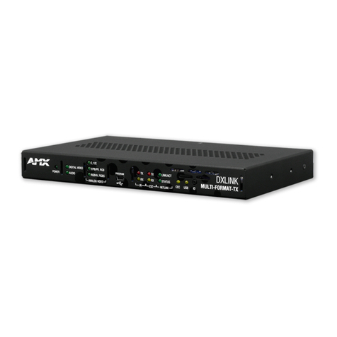
AMX AVB-TX-DGX-HD15-SC Fiber User manual

Instruction Manual
AMX AutoPatch DGX Fiber Modules
DGX Transmitters & Receivers
AVB-TX-DGX-HD15-SC Fiber
AVB-TX-DGX-DVI-SC Fiber
AVB-RX-DGX-SC Fiber-HD15
AVB-RX-DGX-SC Fiber-DVI
REV D: 3/15/2013

AMX Domestic Channel Partner Limited
Warranty, Disclaimer and License
(Excerpt from CHANNEL PARTNER TERMS AND CONDITIONS Versions 11.17.2011 with updates for previous
version 8.25.2010 [sections 6.1 (a), (b) and (f)])
6. LIMITED WARRANTY; RETURN, REPAIR AND REPLACEMENT
6.1 AMX warrants the Products to be free of material defects in materials and workmanship under normal use
for three (3) years from the Shipping Date (or such other period as may be specified below), subject to the
following limitations and exceptions (“Limited Warranty”). For any Product, “Warranty Period” means the
period during which the Limited Warranty is in effect, as set forth herein.
(a) LCD and LED panels are warranted for three (3) years from the Shipping Date, except for the display
and touch overlay components, which are warranted for a period of one (1) year from the Shipping
Date.
(b) Disk drive mechanisms, pan/tilt heads and external power supplies are warranted for a period of
one (1) year from the Shipping Date.
(c) AMX lighting Products are warranted to switch on and off any load that is properly connected to our
lighting Products, as long as the AMX lighting Products are under warranty. AMX also warrants the
control of dimmable loads that are properly connected to our lighting Products. The dimming
performance or quality thereof is not warranted, due to the random combinations of dimmers, lamps
and ballasts or transformers.
(d) AMX software and firmware included in the Products is warranted for a period of ninety (90) days
from the Shipping Date.
(e) Batteries and incandescent lamps are not covered under the Limited Warranty.
(f) The Warranty Period for AMX AutoPatch EPICA, Enova DGX, Modula, Modula Series 4,
Modula Cat Pro Series and 8Y-3000 Product models will continue for the original installation until
five (5) years after the issuance of a PDN with respect to termination of the applicable Product model.
However, if the Product is moved from its original installation to a different installation, the Warranty
Period will automatically become three (3) years from the Shipping Date and, if more than three (3)
years have elapsed since the Shipping Date, the Warranty Period will automatically expire.
Version Date: 11-17-11
Note: The complete Warranty is at www.amx.com.

Contents
i
DGX Transmitters & Receivers Instruction Manual
Contents
ESD Warning .......................................................................................................1
Important Safety Information and Instructions....................................................2
Information et directives de sécurité importantes...............................................3
Notices ................................................................................................................4
Overview and Specifications ...............................................................................7
Applicability Notice ................................................................................................................. 7
Product Notes ......................................................................................................................... 7
Common Applications .............................................................................................................9
AVB-TX-DGX-HD15-SC Fiber................................................................................................. 10
AVB-TX-DGX-DVI-SC Fiber .................................................................................................... 12
AVB-RX-DGX-SC Fiber-HD15................................................................................................. 14
AVB-RX-DGX-SC Fiber-DVI .................................................................................................... 16
DGX TX and DGX RX Specifications...................................................................................... 18
Installation and Setup........................................................................................23
UL Safety Certifications, Notices, and Recommendations for Laser Products ....................... 23
Site Recommendations .......................................................................................................... 24
General Hazard Precautions .................................................................................................. 24
Setup Options ....................................................................................................................... 25
Basic Installation .................................................................................................................... 29
Addressing Special Installation Requirements ....................................................................... 35
Scaling Options .................................................................................................37
Auto Option (SmartScale®) ................................................................................................... 38
Bypass Option ....................................................................................................................... 38
Manual Option and the Scaler Override Utility ..................................................................... 38
Adjusting Video with BoardConfig Software.....................................................45
System Requirements ............................................................................................................ 46
Determining Resolution and Refresh Rate for Source PC ...................................................... 47
Adjusting the Video Image with the DGX-HD15 Wizard ....................................................... 47
EDID Programmer .............................................................................................51
EDID Overview ...................................................................................................................... 51
Determining the Need for EDID Programming ..................................................................... 52
Installing the EDID Programmer............................................................................................ 53
Reading and Saving EDID Data from the Destination Device................................................ 53
Writing EDID Data to the TX ................................................................................................. 55

Contents
ii DGX Transmitters & Receivers Instruction Manual
Troubleshooting ............................................................................................... 57
DGX TX and DGX RX Troubleshooting..................................................................................57
Error Code Reporting (Power LED is Solid Amber)................................................................ 62
Live Status Update Messages ................................................................................................63
Non-DGX Matrix Switcher Routing Behavior .........................................................................64
Technical Support ..................................................................................................................64
Appendix A – Creating a Virtual COM Port...................................................... 67
Establishing a Virtual COM Port ............................................................................................67
Appendix B – Restoring Default Settings ......................................................... 71
Appendix C – Upgrading the Firmware ............................................................ 73

ESD Warning
1
DGX Transmitters & Receivers Instruction Manual
ESD Warning
To avoid ESD (Electrostatic Discharge) damage to sensitive components, make sure you are
properly grounded before touching any internal materials.
When working with any equipment manufactured with electronic devices, proper ESD
grounding procedures must be followed to make sure people, products, and tools are as free of
static charges as possible. Grounding straps, conductive smocks, and conductive work mats
are specifically designed for this purpose.
Anyone performing field maintenance on AMX equipment should use an appropriate ESD field
service kit complete with at least a dissipative work mat with a ground cord and a UL listed
adjustable wrist strap with another ground cord. These items should not be manufactured
locally, since they are generally composed of highly resistive conductive materials to safely
drain static charges, without increasing an electrocution risk in the event of an accident. ESD
protective equipment can be obtained from 3M™, Desco®, Richmond Technology®, Plastic
Systems®, and other such vendors.

Important Safety Information and Instructions
2DGX Transmitters & Receivers Instruction Manual
Important Safety Information and Instructions
When using and installing your AMX product, adhere to the following basic safety precautions.
For more information about operating, installing, or servicing your AMX product, see your
product documentation.
Read and understand all instructions before using and installing AMX products.
Use the correct voltage range for your AMX product.
There are no user serviceable parts inside an AMX product; service should only be
done by qualified personnel.
If you see smoke or smell a strange odor coming from your AMX product, turn it off
immediately and call technical support.
For products with multiple power supplies in each unit, make sure all power supplies
are turned on simultaneously.
Use surge protectors and/or AC line conditioners when powering AMX products.
Only use a fuse(s) with the correct fuse rating in your enclosure.
Make sure the power outlet is close to the product and easily accessible.
Make sure the product is on or attached to a stable surface.
Turn off equipment before linking pieces together, unless otherwise specified in that
product’s documentation.
For safety and signal integrity, use a grounded external power source and a grounded
power connector.
To avoid shock or potential ESD (Electrostatic Discharge) damage to equipment,
make sure you are properly grounded before touching components inside an AMX
product.

Information et directives de sécurité importantes
3
DGX Transmitters & Receivers Instruction Manual
Information et directives de sécurité
importantes
Veuillez vous conformer aux directives de sécurité ci-dessous lorsque vous installez et utilisez
votre appareil AMX. Pour de plus amples renseignements au sujet de l’installation, du
fonctionnement ou de la réparation de votre appareil AMX, veuillez consulter la documentation
accompagnant l’appareil.
Lisez attentivement toutes les directives avant d’installer et d’utiliser les appareils
AMX.
Le voltage doit être approprié à l’appareil AMX.
Les appareils AMX ne contiennent aucune pièce réparable par l’usager; la réparation
ne doit être effectuée que par du personnel qualifié.
Si de la fumée ou une odeur étrange se dégagent d’un appareil AMX, fermez-le
immédiatement et appelez le Service de soutien technique.
Veillez à ce que tous les blocs d’alimentation des appareils dotés de blocs
d’alimentation multiples dans chaque unité soient allumés simultanément.
Servez-vous de protecteurs de surtension ou de conditionneurs de lignes à courant
alternatif lorsque vous mettez les appareils AMX sous tension.
Placez uniquement des fusibles de calibre exact dans les boîtiers.
Veillez à ce que la prise de courant soit proche de l’appareil et facile d’accès.
Veillez à ce que votre appareil AMX soit installé sur une surface stable ou qu’il
y soit fermement maintenu.
Fermez toutes les composantes de l’équipement avant de relier des pièces, à moins
d’indication contraire fournie dans la documentation de l’appareil.
Par mesure de sécurité et pour la qualité des signaux, servez-vous d’une source
d’alimentation externe mise à la terre et d’un connect d’alimentation mis à la terre.
Pour éviter les chocs ou les dommages éventuels causés à l’équipement par une
décharge électrostatique, veillez à ce le dispositif oit bien relié à la terre avant de
toucher les composantes se trouvant à l’intérieur d’un appareil AMX.

Notices
4DGX Transmitters & Receivers Instruction Manual
Notices
Copyright Notice
AMX© 2013 (Rev D), all rights reserved. No part of this publication may be reproduced, stored
in a retrieval system, or transmitted, in any form or by any means, electronic, mechanical,
photocopying, recording, or otherwise, without the prior written permission of AMX. Copyright
protection claimed extends to AMX hardware and software and includes all forms and matters
copyrightable material and information now allowed by statutory or judicial law or herein after
granted, including without limitation, material generated from the software programs which are
displayed on the screen such as icons, screen display looks, etc. Reproduction or disassembly
of embodied computer programs or algorithms is expressly prohibited.
Liability Notice
No patent liability is assumed with respect to the use of information contained herein.
While every precaution has been taken in the preparation of this publication, AMX assumes no
responsibility for error or omissions. No liability is assumed for damages resulting from the use
of the information contained herein.
Further, this publication and features described herein are subject to change without notice.
US FCC Notice
The United States Federal Communications Commission (in 47CFR 15.838) has specified that
the following notice be brought to the attention of the users of this product.
Federal Communication Commission Radio Frequency Interference Statement:
“This equipment has been tested and found to comply with the limits for a Class A digital
device, pursuant to Part 15 of the FCC Rules. These limits are designed to provide reasonable
protection against harmful interference when the equipment is operated in a commercial
environment. This equipment generates, uses, and can radiate radio frequency energy and, if
not installed and used in accordance with the instruction manual, may cause harmful
interference to radio communications. Operation of this equipment in a residential area is likely
to cause harmful interference in which case the user will be required to correct the interference
at his own expense.
If necessary, the user should consult the dealer or an experienced radio/television technician
for additional suggestions. The user may find the booklet, How to Identify and Resolve Radio-
TV Interference Problems, prepared by the Federal Communications Commission to be
helpful.”
This booklet is available from the U.S. Government Printing Office, Washington, D.C. 20402,
Stock N. 004-000-00345-4.
Use shielded cables. To comply with FCC Class A requirement, all external data interface
cables and adapters must be shielded.
Lithium Batteries Notice
Switzerland requires the following notice for products equipped with lithium batteries. This
notice is not applicable for all AMX equipment.
Upon shipment of the products to Switzerland, the requirements of the most up-to-date Swiss
Ordinance Annex 2.15 of SR 814.81 will be met including provision of the necessary markings,
documents, and annual reports relative to the disposal of the batteries to the Swiss Authorities.
Notices
5
DGX Transmitters & Receivers Instruction Manual
Trademark Notices
AMX®, AutoPatch®, NetLinx®, and SmartScale® are trademarks of AMX.
Windows is a registered trademark of Microsoft Corporation in the United States and other
countries.
TeraTerm is a copyright product of T. Teranishi and TeraTerm Project.
PuTTY is a copyright product of Simon Tatham.
HyperTerminal® is a copyright product of Hilgraeve Inc.
3M, Desco®, Richmond Technology®, and Plastic Systems® are registered trademarks.
Ethernet® is a registered trademark of the Xerox Corporation.
ENERGY STAR® is a registered trademark of the U.S. Department of Energy and the
U.S. Environmental Protection Agency
Other products mentioned herein may be the trademarks of their respective owners.
Warnings and Cautions
This manual uses the following conventions and icons to draw attention to actions or conditions
that could potentially cause problems with equipment or lead to personal risk.
ESD Warning: The icon to the left indicates text regarding potential danger associated with the
discharge of static electricity from an outside source (such as human hands) into an integrated
circuit, often resulting in damage to the circuit.
Warning: The icon to the left indicates text that warns readers against actions or conditions that
could cause potential injury to themselves.
Caution: The icon to the left indicates text that cautions readers against actions that could cause
potential injury to the product or the possibility of serious inconvenience.

Notices
6DGX Transmitters & Receivers Instruction Manual

Overview and Specifications
7
DGX Transmitters & Receivers Instruction Manual
Overview and Specifications
Applicability Notice
The information in this manual applies to the four DGX Transmitter (TX) and Receiver (RX) modules
listed in the table below.
Important: These modules are compatible only with each other and with other AMX DGX Signal
Management products.
DGX TX and DGX RX Modules
* The supported analog video formats for this model TX are RGBHV, RGBS, RGsB, and Y/Pb/Pr video (Y/Pb/Pr
up to 1080p).
Product Notes
Either of the DGX Fiber TX modules listed can be paired with either of the DGX Fiber RX modules
as an end-to-end solution for transmission over single fiber or any of the modules can be used as an
integrated part of an AMX DGX matrix switcher that supports single fiber transmission. This manual
contains complete information for stand-alone use. For use in a system with a distribution matrix, see
page 25 in this manual and the distribution matrix’s Instruction Manual at www.amx.com.
The following descriptions explain how the modules work as an end-to-end solution. The TX and RX
work in the same way when used in conjunction with DGX Fiber boards in a DGX matrix switcher.
DGX Fiber TX Modules –two types of transmitter modules are available, one model is for analog
signals and the other model is for a DVI signal. The analog module receives RGBHV, RGBS, RGsB, or
Y/Pb/Pr video signals, and the DVI Fiber module receives a DVI video signal from the source device.
The modules also receive either a digital audio signal or an analog stereo audio signal from the source
device (digital takes precedence if both are connected). Both the video and audio signals are transmitted
over an SC terminated fiber cable to a DGX RX module. The RS-232 port on each TX supplies
unidirectional RS-232 serial data over the SC terminated fiber cable with the data flow in the same
direction as the video signal. In addition to supporting transmission of incoming signals, the DGX TX
modules also include a local video output connector for sending the video signal directly from the source
to a local destination device.
DGX Fiber RX Modules –two types of receiver modules are available to accept the signal from a TX
module’s SC terminated fiber cable. The DGX HD-15 RX converts the video signal to RGBHV for the
destination device, and the DGX DVI RX converts the video signal to DVI for the destination device.
Both modules feature SmartScale®(integrated EDID output scaling) to make sure the output resolution
is appropriate regardless of the type of incoming video. They also support a Manual (override) option for
setting up custom resolutions and a Bypass option. The audio on the RX is output on both the digital
audio port and the analog stereo audio port. The RS-232 port on each RX accepts any unidirectional
RS-232 serial data over the SC fiber from the TX.
FG # Type Model Description
FG1010-200-01 TX AVB-TX-DGHD15-SC Fiber Analog video* + analog or digital audio over SC fiber
FG1010-210-01 TX AVB-TX-DGX-DVI-SC Fiber DVI video + analog or digital audio over SC fiber
FG1010-400-01 RX AVB-RX-DGX-SC Fiber-HD15 SC fiber to RGBHV video + analog and digital audio
FG1010-410-01 RX AVB-RX-DGX-SC Fiber-DVI SC fiber to DVI video + analog and digital audio

Overview and Specifications
8DGX Transmitters & Receivers Instruction Manual
DGX TX and DGX RX Module Features
Designed for use with single strand multimode fiber cable with SC connectors.
DGX technology provides a common signal transport and matrix switching layer that
transcodes between analog and digital signals; this allows compatibility among all the
AMX DGX Fiber modules and with other AMX DGX Signal Management products.
Provides secure transmission of uncompressed DVI or RGBHV up to 3,000 feet (914 m) at
resolutions up to 1920x1200 @ 60 Hz, including 1080p. This distance applies to both ends
when modules are used in a system with a DGX Matrix Switcher’s Fiber boards.
Auto-Detect on the transmitters and SmartScale®on the receivers work to automatically
recognize any device’s supported resolution and signal style parameters, allowing switching
out source devices and destination devices without manual setup.
SmartScale®is the ability to configure the scaling output by automatically selecting
destination defined resolutions; the product also has the ability to control detailed timing
parameters for customized video output formats.
EDID support and integrated EDID output scaling, which scales any incoming signal to the
EDID declared preferred resolution of the attached destination (this feature can be overridden
or bypassed).
Custom EDID settings can be loaded on each input with the use of the included EDID
Programmer.
DGX HD-15 TX has the ability to detect an incoming analog signal (video or audio) and
automatically convert it to a digital signal (this feature can be overridden).
DGX HD-15 TX supports RGBHV, RGBS, RGsB, and Y/Pb/Pr (Y/Pb/Pr up to 1080p) video
formats.
DGX HD-15 RX supports an RGBHV video format.
DGX DVI TX and DGX DVI RX support a DVI video format.
Both TX modules accept analog stereo audio signals (unbalanced stereo) or digital audio
signals (PCM over S/PDIF @ 32 kHz, 44.1 kHz, 48 kHz). Analog stereo audio signals are
automatically converted to a digital signal.
Both RX modules send analog and digital audio signals.
Compare auto and manual video settings on the DGX HD-15 TX with the press of a button.
Supports progressive scanning (for optimal results) and interlaced scanning (for supported
resolutions, see page 20).
All modules support RS-232 port (3-position terminal block) unidirectional serial data from
source to destination.
Standard USB (mini-B) port can be used as a virtual COM port for serial communication with
a PC for overriding the AutoAD settings, adjusting the video signal with BoardConfig
software if necessary, making field upgrades (through an Upgrade Tool), and reporting errors.
BoardConfig software for the DGX HD-15 TX is available for user adjustable contrast,
brightness, and position.
Desktop power supply (ENERGY STAR®qualified) provided per module.
HD-15 to BNC breakout cable and HD-15 to RCA breakout cable are available.
Compatible with all V Style versatile mounting options including rack, surface, or pole.
Backed by AMX 3 year warranty (see www.amx.com).
24-hour technical support.
Note: Features and specifications described in this document are subject to change without notice.

Overview and Specifications
9
DGX Transmitters & Receivers Instruction Manual
Common Applications
AMX DGX Fiber Transmitters and Receivers pass digital or analog audio and video over fiber optic
cable from the source to display device. Fiber uses light, rather than electrical signals, to send data,
which is especially suitable for government and military facilities as it is not susceptible to non-intrusive
physical wire tapping. AMX DGX Fiber Transmitters and Receivers provide secure signal transport up
to 3,000 feet (914.4 m) without losing signal clarity making it ideal for use throughout classrooms,
auditoriums, conference rooms, hospitals, and campuses. With SmartScale®technology and simple
installation and termination of fiber cable, AMX DGX Fiber Transmitters and Receivers are the perfect
solution for commercial and residential installations.
FIG. 1 AMX DGX Fiber Transmitters and Receivers in single building setup
FIG. 2 AMX DGX Fiber Transmitters and Receivers in multiple building setup

Overview and Specifications
10 DGX Transmitters & Receivers Instruction Manual
AVB-TX-DGX-HD15-SC Fiber
DGX HD-15 TX Front View
The following components are located on the front of the DGX HD-15 TX (left to right):
Power LED – indicates whether or not the module is powered on.
Video and Audio LEDs – indicate the presence of video and audio signals through the
module.
EDID LED – when the module is in Write-Protect mode, the LED is off (default state); when
the module is in Write-Enable mode, the LED is green. The EDID switch is on the rear.
Video Type LEDs – indicate type of signal present: “Y/PB/PR, RGB” or “RGBHV, RGBS.”
Mode (resolution) button and Auto and Manual LEDs – use the Mode button to toggle
between Auto mode (the default mode) and Manual mode to view the difference on the
display when adjusting settings with BoardConfig.
USB mini-B port – connect to a control PC and use for overriding the automatic conversion
settings, signal adjustment, firmware upgrades through an Upgrade Tool, live status updates,
and error code reporting.
Important: If the indicator LEDs do not respond with a normal display as stated in the table below,
check all power connections before contacting technical support (see page 57).
* When a USB cable is connected, the Power LED blinks red while communication is being established with the
PC (see page 67).
** Other than when adjusting settings in BoardConfig, an illuminated Manual LED has no special significance as
the Auto and Manual settings are identical by nature once changes are saved.
FIG. 3 DGX HD-15 TX front view
TX Indicator LEDs
LED Normal Display Indicates
Power* Constant green Power is applied to module (initially red at start up).
Video Constant green A video signal is present through module.
Audio Constant green An audio signal is present through module.
EDID Off EDID is in Write-Protect mode (EDID switch on rear flipped down).
Y/PB/PR, RGB Constant green A Y/Pb/Pr or RGsB signal is present through module.
RGBHV, RGBS Constant green An RGBHV or RGBS signal is present through module.
Auto
Manual
One is constant green;
the other is off
Module is in Auto mode (default).
Module is in Manual mode** (the mode for adjusting settings when
using BoardConfig).
EDID LED
Power LED
Signal presence LEDs - Video and Audio
Video Type LEDs
USB mini-B port
Mode (resolution) button and LEDs - Auto and Manual

Overview and Specifications
11
DGX Transmitters & Receivers Instruction Manual
DGX HD-15 TX Rear View
The following components are located on the rear of the DGX HD-15 TX (from left to right):
Power receptacle – a 2.1 mm DC jack for connecting power (an ENERGY STAR®qualified
desktop power supply is provided).
RS-232 (serial data interface) port – 3-position screw terminal block for unidirectional
data transfer from the source device to the destination device.
Video Input – HD-15 connector for an RGBHV video input signal.
Video Local Output – HD-15 connector for sending the video signal from the video input
connector to a local destination device.
Digital Audio – RCA jack for a digital audio input signal.
Stereo Audio – 3.5 mm jack for an analog stereo audio signal.
SC Fiber Output – accepts a standard 2.5 mm SC fiber connector (standardized in TIA-568A)
that snaps into place.
EDID switch – the default is set to WP (write protect), so source and destination can share
information; set to W for write enable. The EDID LED is on the front.
Sync Set switch – must be set to match the video format of the source signal (see page 32).
Special Product Information
If a video signal is not present on the TX, the lasers are disabled and will not transmit any video, audio,
or serial data to the RX.
A short lapse/drop of the serial data is to be expected under certain instances, e.g., when the digital audio
is unplugged or plugged or when the sample rate frequency of the digital audio changes.
FIG. 4 DGX HD-15 TX rear view
Digital (RCA digital audio input)
Video (HD-15) Input
Video (HD-15) Local Output
Power Jack
Fiber (SC) Output
EDID W / WP Switch
and Sync Set B / A Switch
RS-232 (Serial Data Interface) Port
Stereo (3.5 mm analog stereo audio input)

Overview and Specifications
12 DGX Transmitters & Receivers Instruction Manual
AVB-TX-DGX-DVI-SC Fiber
DGX DVI TX Front View
The following components are located on the front of the DGX DVI TX (left to right):
Power LED – indicates whether or not the module is powered on.
Video and Audio LEDs – indicate the presence of video and audio signals through the
module.
EDID LED – when the module is in Write-Protect mode, the LED is off (default state); when
the module is in Write-Enable mode, the LED is green. The EDID switch is on the rear.
USB mini-B port – connect to a control PC and use for overriding the automatic conversion
settings, signal adjustment, firmware upgrades through an Upgrade Tool, live status updates,
and error code reporting.
Important: If the indicator LEDs do not respond with a normal display as stated in the table below,
see “Troubleshooting” on page 57.
* When a USB cable is connected, the Power LED blinks red while communication is being established with the
PC (see page 67).
FIG. 5 DGX DVI TX front view
TX Indicator LEDs
LED Normal Display Indicates
Power* Constant green Power is applied to module (initially red at start up).
Video Constant green A video signal is present through module.
Audio Constant green An audio signal is present through module.
EDID Off EDID is in Write-Protect mode (EDID switch on rear flipped down).
EDID LED
Power LED
Signal presence LEDs - Video and Audio
USB mini-B port

Overview and Specifications
13
DGX Transmitters & Receivers Instruction Manual
DGX DVI TX Rear View
The following components are located on the rear of the DGX DVI TX (left to right):
Power receptacle – a 2.1 mm DC jack for connecting power (an ENERGY STAR®qualified
desktop power supply is provided).
RS-232 (serial data interface) port – 3-position screw terminal block for unidirectional
data transfer from the source device to the destination device.
Video Input – DVI-I connector for a DVI video input signal.*
Video Local Output – DVI-I connector for sending a DVI video signal to a local destination
device.*
Digital Audio – RCA jack for a digital audio input signal.
Stereo Audio – 3.5 mm jack for an analog stereo audio signal.
SC Fiber Output – accepts a standard 2.5 mm SC fiber connector (standardized in TIA-568A)
that snaps into place.
EDID switch – the default is set to WP (write protect), so source and destination can share
information; set to W for write enable. The EDID LED is on the front.
* DGX DVI Modules only support digital, single link (DVI-D) signals. The connectors on the module
are DVI-I connectors, which allow use of a cable with either a DVI-D or a DVI-I connector (for DVI-I,
the analog pins are not used; see the DVI-I connector pinout information on page 28). This also holds
true for DGX DVI Boards in DGX Matrix Switchers.
Special Product Information
If a video signal is not present on the TX, the lasers are disabled and will not transmit any video, audio,
or serial data to the RX.
A short lapse/drop of the serial data is to be expected under certain instances, e.g., when the digital audio
is unplugged or plugged or when the sample rate frequency of the digital audio changes.
FIG. 6 DGX DVI TX rear view
Digital (RCA digital audio input)
Video (DVI) Input
Video (DVI) Local Output
Power Jack
Fiber (SC) Output
EDID W / WP Switch
RS-232 (Serial Data Interface) Port
Stereo (3.5 mm analog stereo audio input)

Overview and Specifications
14 DGX Transmitters & Receivers Instruction Manual
AVB-RX-DGX-SC Fiber-HD15
DGX HD-15 RX Front View
The following components are located on the front of the DGX HD-15 RX (left to right):
Power LED – indicates whether or not the module is powered on.
Video and Audio LEDs – indicate the presence of video and audio signals through the
module.
Scaling button and LEDs – use Scaling button to select one of the 3 Scaling options: Bypass,
Auto, or Manual.
USB port (mini-B) – connect to a control PC and use for overriding automatic conversion
settings, signal adjustment, if necessary, firmware upgrades through an Upgrade Tool, live
status updates, and error code reporting.
Important: If the indicator LEDs do not respond with a normal display as stated in the table below,
see “Troubleshooting” on page 57.
* When a USB cable is connected, the Power LED blinks red while communication is being established with the
PC (see page 67).
** If the output cable is disconnected from the RX or if no EDID can be found on the destination device, the
Bypass LED will be constant green and the Auto LED will blink. This indicates that the RX has switched to the
Bypass Scaling option and is waiting for EDID information. As soon as a valid EDID is found, the RX will revert to
the Auto Scaling option.
FIG. 7 DGX HD-15 RX front view
RX Indicator LEDs
LED Normal Display Indicates
Power* Constant green Power is applied to module.
Video Constant green A video signal is present through module.
Audio Constant green An audio signal is present through module.
Scaling – Bypass
– Auto (default)
– Manual
One is constant green;
the other two are off
Module is in one of the three modes for scaling.
At initial power up, the RX defaults to the Auto
Scaling option.**
Press Scaling button to turn on the Bypass option
or Manual option.
Signal presence LEDs - Video and Audio
Power LED
Scaling button and LEDs - Bypass, Auto, and Manual
USB mini-B port

Overview and Specifications
15
DGX Transmitters & Receivers Instruction Manual
DGX HD-15 RX Rear View
The following components are located on the rear of the DGX HD-15 RX (left to right):
Power receptacle – a 2.1 mm DC jack for connecting power (an ENERGY STAR®qualified
desktop power supply is provided).
RS-232 (serial data interface) port – 3-position screw terminal block accepts unidirectional
data transfer from the TX (source device to destination device).
Video Output – HD-15 connector for an RGBHV video output signal.
Digital Output – RCA jack for a digital audio output signal.
Stereo Output – standard 3.5 mm jack for an analog stereo audio output signal.
SC Fiber Input – accepts a standard 2.5 mm SC fiber connector (standardized in TIA-568A)
that snaps in.
Warning: Do not use the Stereo output connector as a headphone jack. The Stereo output is set at
unity gain (line-level) and is not intended for headphones.
Special Product Information
If a video signal is not present on the TX, the lasers are disabled and will not transmit any video, audio,
or serial data to the RX.
A short lapse/drop of the serial data is to be expected under certain instances, e.g., when the digital audio
is unplugged or plugged or when the sample rate frequency of the digital audio changes.
FIG. 8 DGX HD-15 RX rear view
RS-232 Port Digital (RCA digital audio output)
Power Jack
SC Fiber Input
HD-15 Output
Stereo (3.5 mm analog stereo audio output)

Overview and Specifications
16 DGX Transmitters & Receivers Instruction Manual
AVB-RX-DGX-SC Fiber-DVI
DGX DVI RX Front View
The following components are located on the front of the DGX DVI RX (left to right):
Power LED – indicates whether or not the module is powered on.
Video and Audio LEDs – indicate the presence of video and audio signals through the
module.
Scaling button and LEDs – use Scaling button to select one of the 3 Scaling options: Bypass,
Auto, or Manual.
USB port (mini-B) – connect to a control PC and use for overriding automatic conversion
settings, signal adjustment, if necessary, firmware upgrades through an Upgrade Tool, live
status updates, and error code reporting.
Important: If the indicator LEDs do not respond with a normal display as stated in the table below,
see “Troubleshooting” on page 57.
* When a USB cable is connected, the Power LED blinks red while communication is being established with the
PC (see page 67).
** If the output cable is disconnected from the RX or if no EDID can be found on the destination device, the
Bypass LED will be constant green and the Auto LED will blink. This indicates that the RX has switched to the
Bypass Scaling option and is waiting for EDID information. As soon as a valid EDID is found, the RX will revert to
the Auto Scaling option.
FIG. 9 DGX DVI RX front view
RX Indicator LEDs
LED Normal Display Indicates
Power* Constant green Power is applied to module.
Video Constant green A video signal is present through module.
Audio Constant green An audio signal is present through module.
Scaling – Bypass
– Auto (default)
– Manual
One is constant green;
the other two are off
Module is in one of the three modes for scaling.
At initial power up, the RX defaults to the Auto
Scaling option.**
Press Scaling button to turn on the Bypass option
or Manual option.
Signal presence LEDs - Video and Audio
Power LED
Scaling button and LEDs - Bypass, Auto, and Manual
USB mini-B port
Other manuals for AVB-TX-DGX-HD15-SC Fiber
1
This manual suits for next models
3
Table of contents
Other AMX Transmitter manuals

AMX
AMX TX64 User manual

AMX
AMX Classroom Transmitter TX-CT5 User manual

AMX
AMX TXC4 Series User manual

AMX
AMX DTV-TX01-DVB-T User manual

AMX
AMX DTV-TX03-US User manual

AMX
AMX TX64 Quick start guide

AMX
AMX UPX-HDMI+A HDMI Operating and maintenance instructions

AMX
AMX DXLITE DXL-TX-4K60 User manual

AMX
AMX Classroom Transmitter TX-CT5 Quick start guide

AMX
AMX DUX-MTX User manual