Anaheim Automation DPMLP601 User manual
1
#L010168 January 2005
DPMLP601DPMLP601
DPMLP601DPMLP601
DPMLP601
Programmable Driver PackProgrammable Driver Pack
Programmable Driver PackProgrammable Driver Pack
Programmable Driver Pack
User’s GuideUser’s Guide
User’s GuideUser’s Guide
User’s Guide
910 East Orangefair Lane, Anaheim, CA 92801
website: www.anaheimautomation.com
ANAHEIM AUTOMATION, INC.ANAHEIM AUTOMATION, INC.
ANAHEIM AUTOMATION, INC.ANAHEIM AUTOMATION, INC.
ANAHEIM AUTOMATION, INC.

2
#L010168 January 2005
Table of ContentsTable of Contents
Table of ContentsTable of Contents
Table of Contents
Section 1: IntroductionSection 1: Introduction
Section 1: IntroductionSection 1: Introduction
Section 1: Introduction ..................................................................................................................................................................................................................................................................................
..................................................................................................................................................................................................................................................................................
......................................................................................................................................... 33
33
3
Description .............................................................................................................................................................. 3
Electrical Specifications ........................................................................................................................................... 4
OrderingInformation................................................................................................................................................ 4
Dimensions/SwitchLocations .................................................................................................................................. 5
Wiring Diagrams ...................................................................................................................................................... 5
Terminal Descriptions - Power................................................................................................................................. 6
Terminal Descriptions - Driver ................................................................................................................................. 6
Terminal Descriptions - Controller ........................................................................................................................... 7
Connector Descriptions - Controller......................................................................................................................... 7
Slide Switch Descriptions - Controller...................................................................................................................... 7
Section 2: Driver FunctionsSection 2: Driver Functions
Section 2: Driver FunctionsSection 2: Driver Functions
Section 2: Driver Functions ....................................................................................................................................................................................................................................................................
....................................................................................................................................................................................................................................................................
.................................................................................................................................. 88
88
8
Motor Selection........................................................................................................................................................ 8
Step Motor Current Setting Guide............................................................................................................................ 8
Microstep Selection (SW1 Settings) ........................................................................................................................ 9
Setting the Output Current....................................................................................................................................... 9
Reducing Output Current....................................................................................................................................... 10
Determining Output Current................................................................................................................................... 10
Step Motor Configurations ..................................................................................................................................... 10
Connecting the Step Motor .................................................................................................................................... 12
Short-Circuit, Mis-Wire, and Over-Current Conditions ........................................................................................... 12
Over-Temperature and Over-Voltage Conditions .................................................................................................. 12
Section 3: Controller FunctionsSection 3: Controller Functions
Section 3: Controller FunctionsSection 3: Controller Functions
Section 3: Controller Functions ..................................................................................................................................................................................................................................................
..................................................................................................................................................................................................................................................
......................................................................................................................... 1313
1313
13
Methods of Communication ................................................................................................................................... 13
Baud Rate ............................................................................................................................................................. 13
RS232 Protocol - SW1 in RS232 position.............................................................................................................. 13
RS485 Protocol - SW1 in RS485 position............................................................................................................. 13
Axis Selection ........................................................................................................................................................ 14
Controller Status LED ............................................................................................................................................ 14
Technical Support.................................................................................................................................................. 14
Section 4: SMC60WIN SoftwareSection 4: SMC60WIN Software
Section 4: SMC60WIN SoftwareSection 4: SMC60WIN Software
Section 4: SMC60WIN Software ..................................................................................................................................................................................................................................................
..................................................................................................................................................................................................................................................
......................................................................................................................... 1919
1919
19
File Menu............................................................................................................................................................... 20
Setup Menu ........................................................................................................................................................... 20
Setup - Axis Menu ................................................................................................................................................. 20
Program Menu....................................................................................................................................................... 21
Program - Autostart Program Menu....................................................................................................................... 21
Edit Menu .............................................................................................................................................................. 21
Help Menu ............................................................................................................................................................. 22
“The Unit is Connected” / “The Unit is NOT Connected”........................................................................................ 22
Toolbar .................................................................................................................................................................. 23
Tab Sheets ............................................................................................................................................................ 23
Tab Sheets - Real Time Motion ............................................................................................................................. 24
Tab Sheets - Encoder Options and Registration Inputs ......................................................................................... 25
Tab Sheets - Analog Input and Thumbwheel Options............................................................................................ 26
Tab Sheets - Create and Edit Program.................................................................................................................. 27
Add/Change/InsertCommands ............................................................................................................................. 28
Add Tab Sheets - Motion Commands.................................................................................................................... 29
Add Tab Sheets - If/Then and Output Commands ................................................................................................. 30
Add Tab Sheets - Goto, For Loops, Encoder and Thumbwheel Commands ......................................................... 31
Add Tab Sheets - Analog, Registration and Text Commands................................................................................ 32
Calculator .............................................................................................................................................................. 33
Section 5: Direct Talk ModeSection 5: Direct Talk Mode
Section 5: Direct Talk ModeSection 5: Direct Talk Mode
Section 5: Direct Talk Mode................................................................................................................................................................................................................................................................
................................................................................................................................................................................................................................................................
................................................................................................................................3434
3434
34
Section 6: TroubleshootingSection 6: Troubleshooting
Section 6: TroubleshootingSection 6: Troubleshooting
Section 6: Troubleshooting ................................................................................................................................................................................................................................................................
................................................................................................................................................................................................................................................................
................................................................................................................................4444
4444
44
Error Codes ........................................................................................................................................................... 45
Section 7: Sample ProgramsSection 7: Sample Programs
Section 7: Sample ProgramsSection 7: Sample Programs
Section 7: Sample Programs ............................................................................................................................................................................................................................................................
............................................................................................................................................................................................................................................................
.............................................................................................................................. 4646
4646
46
Appendix 1: ASCII Table for Direct Mode .............................................................................................................. 51

3
#L010168 January 2005
Section 1: IntroductionSection 1: Introduction
Section 1: IntroductionSection 1: Introduction
Section 1: Introduction
The DPMLP601 is a single-axis 8A, 160V motor bus voltage, bipolar microstep motor driver with a control-
ler containing 2 Kbytes of nonvolatile stored programming space and quadrature encoder feedback pack-
age. It provides flexible, independent control of bipolar step motors with a current range from 1.5 to 8.0
amps/phase and a fixed microstepping resolution of 1000 steps per revolution from a computer, or any
machine controller with a serial port. With an input voltage of 90-132 VAC (50/60Hz), no external power
supplies or transformers are needed. It is also capable of stand-alone operation, making it an embedded
machine controller. The easy to use Windows software, SMC60WIN, can be used to directly control
motion and to program the DPMLP601. The DPMLP601 also has the ability for real time functions.
The DPMLP601 has 40 commands, which are easy-to-remember for direct movement of the step motor
and communicates via either an RS232 or RS485 bidirectional serial data bus. Up to 99 DPMLP601’s can
be networked from one communications port on your PC or PLC, utilizing the RS485 communications
protocol. Special functions of the controller include 8 programmable open collector outputs and 6 TTL,
CMOS and 24V compatible inputs, a quadrature encoder input with the ability to autocorrect, an analog
input to control either maximum speed or absolute position, registration mark indexing during a slew
command, an output that will trigger during an index command at an absolute position, and a thumbwheel
input for indexing a motor. The DPMLP601 can be powered from 90-132 VAC, 50/60Hz,
DescriptionDescription
DescriptionDescription
Description
The driver in the DPMLP601 (MLP08641) is a microstep motor driver that can drive motors rated from 1.5
to 8.0 amps/phase. It has a fixed mictrostepping resolution of 1000 steps per revolution. It can handle 4,
6and8-leadmotors inabipolarfashion. TheDPMLP601’sdriver featuresmotorcurrentON/OFFcapabilities
and a Reduced Current Enable to automatically reduces motor current to 50% of the set value after the
last step is made (1sec delay). Protection devices have been added to this driver for short circuit, open
circuit, over voltage, under voltage and over temperature conditions. The driver has built-in features to
indicate power on (Green LED), Clocks being received (Yellow LED) and fault conditions (Red LED).
Thecontrollerin theDPMLP601(PCL601) providesindependentprogramming ofacceleration/deceleration,
base speed (start up speed), max speed (running speed), jog speed, and the number of steps to be taken
in both relative and absolute positioning modes. On absolute positioning moves, the DPMLP601
automaticallydetermines theproperdirection togo andthe numberofstepstotake. Therelative positioning
will move a number of steps in the direction that the user defines. The DPMLP601 also has specific
functions such as
encoder feed back, autocorrection, index-on-the-fly and output-on-the-fly
. An analog
input can be used to set either the maximum speed or goto an absolute position based between the upper
and lower programmable limits. A seven decade thumbwheel switch can be read for relative indexing. The
DPMLP601also has ahigh levelprogramming command setthat includes:branching, looping, conditional
statements, time delays, text strings, and I/O which the user can use in the programming mode to fully
control all machine functionality. A home input, a set of bidirectional hard and soft limit switch inputs and
bidirectional jog inputs are provided for each axis. These features are generally required in most machine
control designs. 6 testable TTL, CMOS and 24V compatible inputs and 8 programmable open-collector
outputs are provided per axis. The I/O may be used for monitoring and controlling machine operation and/
or interaxis coordination. The I/O are accessible independent of the busy state of the axis controls. The
DPMLP601 has a built-in programmable reset circuit. Reset is automatic on power-up, or by pressing the
external reset button.

4
#L010168 January 2005
Electrical SpecificationsElectrical Specifications
Electrical SpecificationsElectrical Specifications
Electrical Specifications
Power Requirements:Power Requirements:
Power Requirements:Power Requirements:
Power Requirements:
90-132 VAC 50/60Hz
Operating Temperature:Operating Temperature:
Operating Temperature:Operating Temperature:
Operating Temperature:
0 to 60 degrees C
Pulse Output Range:Pulse Output Range:
Pulse Output Range:Pulse Output Range:
Pulse Output Range:
1 to 50,000 Hz
10uS negative going pulse width
Inputs (TTL-CMOS):Inputs (TTL-CMOS):
Inputs (TTL-CMOS):Inputs (TTL-CMOS):
Inputs (TTL-CMOS):
Logic “0”: 0 to 0.8VDC
Logic “1”: 3.5 to 24VDC
Analog input 1: 0 to 5VDC
Output Current Rating:Output Current Rating:
Output Current Rating:Output Current Rating:
Output Current Rating:
8 A/phase maximum
Baud Rate:Baud Rate:
Baud Rate:Baud Rate:
Baud Rate:
38400 Baud, Fixed
Data Format:Data Format:
Data Format:Data Format:
Data Format:
Half-Duplex, 1 start bit, 8 data bits,
no parity, 1 stop bit
Outputs (8 programmable I/O and fault out):Outputs (8 programmable I/O and fault out):
Outputs (8 programmable I/O and fault out):Outputs (8 programmable I/O and fault out):
Outputs (8 programmable I/O and fault out):
Open Drain Type
40V, 100mA
+5VDC Output, 50mA
Output1 active time for output on the fly:Output1 active time for output on the fly:
Output1 active time for output on the fly:Output1 active time for output on the fly:
Output1 active time for output on the fly:
50uS
Note:Note:
Note:Note:
Note: For inductive loads, customers must connect
a clamping diode to protect from flyback voltage
spikes.
rebmuNtraP noitpircseD
106PLMPD egatlovsubrotomV061htiwevirdralopibpma8aserutaeF-kcaPevirD/rellortnoC
10601NPD ylppusrewopdnaevirdralopibpma01aserutaeF-kcaPevirD/rellortnoC
10657DPD ylppusrewopdnaevirdralopinupma7aserutaeF-kcaPevirD/rellortnoC
BT9DS584retrevnoc584SRot232SR
7SWT 106PLMPDhtiwelbitapmochctiwsleehwbmuhtnoitisopneveS
6-CFM9AA .rotcennocelamef9BDenodnaelam9BDenohtiwelbaclaireshguorhtthgiartstoof6
Ordering InformationOrdering Information
Ordering InformationOrdering Information
Ordering Information
Thetable belowlists avariety of productsavailable fromAnaheim Automation,Inc. Theseproducts include
those covered by this manual, along with supporting cables and devices. We are continually adding new
products to our line, so please consult Anaheim Automation, Inc. or its representatives for information on
the latest releases.
A CD, provided when you purchase the unit, contains this user’s manual, along with the SMC60WIN
software and DPMLP601 program examples. The software allows you to write and change programs that
are to be stored in the DPMLP601 for autostart use, and also upload the program that is stored in the
DPMLP601 itself for editing and viewing. The software also allows you to save the programs onto your
computer hard drive, and easily retrieve them when needed.
5
#L010168 January 2005
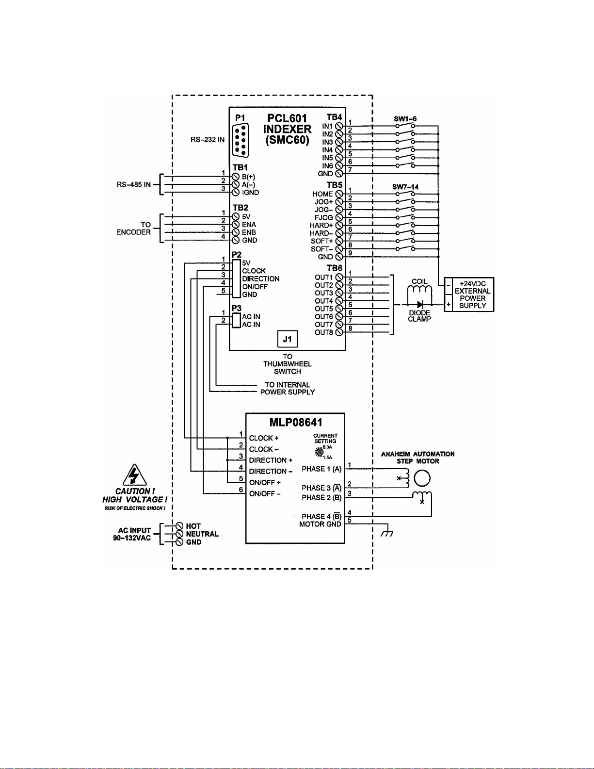
Wiring/Hook-up DiagramWiring/Hook-up Diagram
Wiring/Hook-up DiagramWiring/Hook-up Diagram
Wiring/Hook-up Diagram
Table of contents
Other Anaheim Automation Industrial Equipment manuals


