HMC-T2000 User’s Manual HMC119983 Rev 1
2
List of Contents
1Introduction............................................................................................................................................................. 2
2Package Contents.................................................................................................................................................. 3
3General Overview of instrument capabilities.......................................................................................................... 3
4Installation of Equipment and Safety...................................................................................................................... 4
5Operation and Setup .............................................................................................................................................. 5
6Maintenance......................................................................................................................................................... 23
7Programming........................................................................................................................................................ 27
8Technical Support................................................................................................................................................. 27
9Warranty............................................................................................................................................................... 27
10 Appendix............................................................................................................................................................... 27
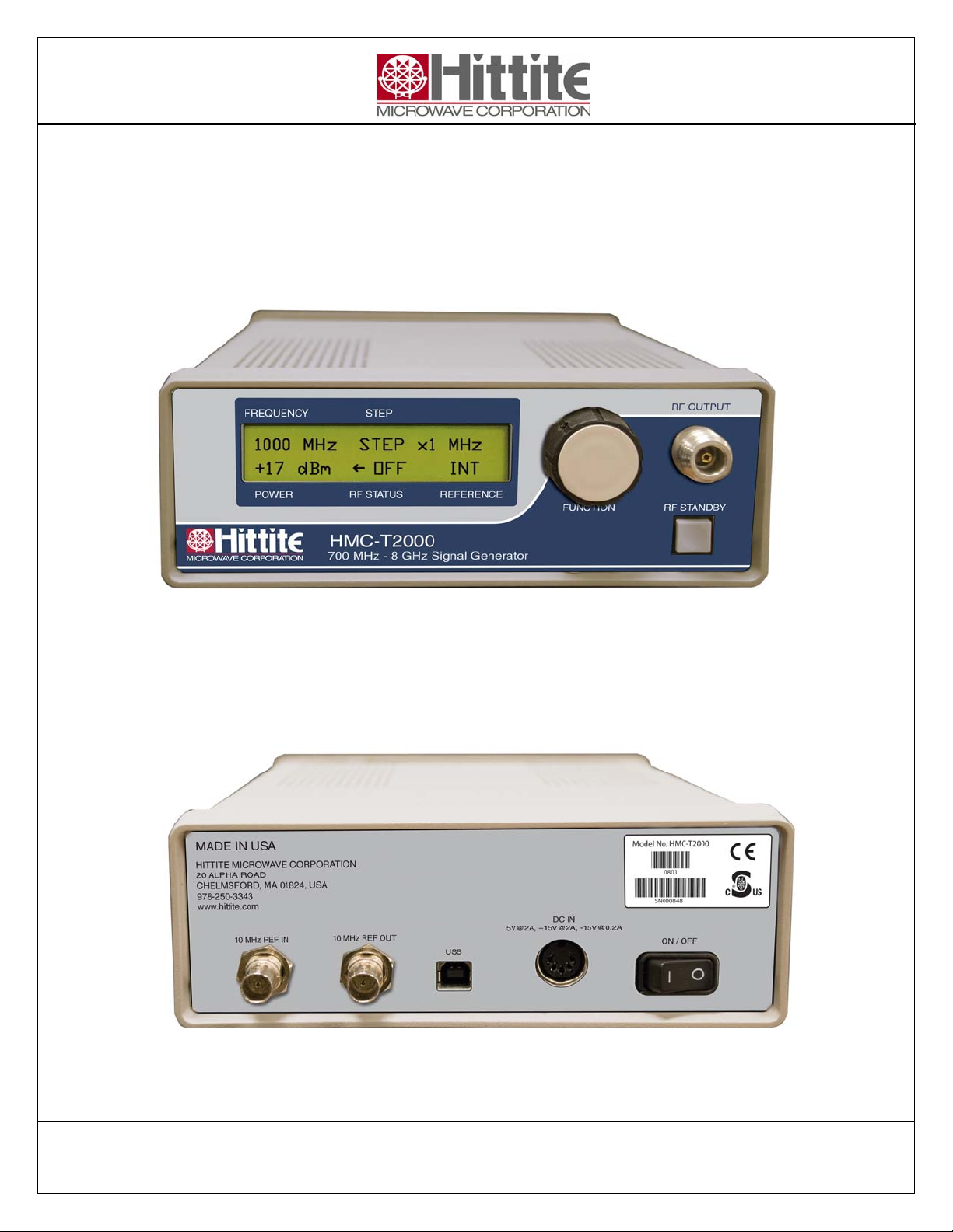
1 Introduction
This User’s Manual describes the HMC-T2000 700MHz to 8000MHz Synthesized Signal Generator
unit (SG). Most of the pertinent information can be quickly located through the table of contents and
highlighted sections.
The following conventions and indicators are used in this user’s guide:
This indicator calls attention to critical or important information, concerning an operation or
maintenance procedure or practice, which if not strictly followed and observed, could
potentially result in serious injury to operating personnel. An example, is the proximity of high
AC line voltage.
This indicator draws attention to a situation relating to the equipment set-up, operating or
maintaining the equipment, which if not observed, could result in permanent damage to
sensitive microwave devices or other electronic compnents.
This indicator highlights a required equipment preparation, fundamental procedure, practice,
condition or statement. Other indicators in bold BLUE capital lettering emphasize important
points of information, input or output connections and signal generator specification headings.
Notice
Hittite Microwave Corporation has prepared this manual for use by Hittite personnel and
customers as a guide for the proper installation, operation, and maintenance of Hittite equipment
and computer programs. The drawings, specifications, and information contained herein are the
property of Hittite Microwave Corporation, and any unauthorized use or disclosure of these
drawings, specifications, and information is prohibited; they shall not be reproduced, copied, or
used in whole or in part as the basis for manufacture or sale of the equipment or software
programs without the prior written consent of Hittite Microwave Corporation.