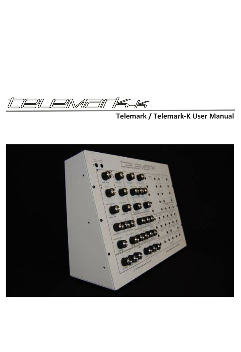
Analogue Solutions Telemark User manual

analogue solutions Semblance/Telemark e&oe (c) 5-3-09
1
user manual
Semblance
Telemark
(Semblance Modular)

analogue solutions Semblance/Telemark e&oe (c) 5-3-09
2
Contents
SPECIFICATION...........................................................................4
INTRODUCTION...........................................................................6
APPLICATIONS............................................................................6
SAFETY INSTRUCTIONS ............................................................7
INITIAL TUNING...........................................................................8
CIRCUITS IN DETAILS.................................................................8
VCO1.............................................................................................9
VCO2...........................................................................................10
SYNC...........................................................................................11
NOISE GENERATOR .................................................................12
MIXER.........................................................................................12
VCF .............................................................................................13
Filtering External Sound Sources............................................15
ENVELOPE GENERATORS.......................................................16
EG1 ASR.....................................................................................16
EG2 ASR.........................................................................................
VCA.................................................................................................
LFO .................................................................................................
MIDI to CV CONVERTER...............................................................
EG2 ASR.....................................................................................17
VCA.............................................................................................17
LFO / Sample and Hold.............................................................18
REAR PANEL.............................................................................20
REAR PANEL DETAILS.............................................................21
REAR PANEL AUDIO CONNECTIONS.....................................22
NO SIGNAL? ..............................................................................23
QUICK METHOD FOR ZERO MODULATION ...........................23
EXPANSION ...............................................................................23
INTERNAL CALIBRATION OF VCOs........................................23
MIDI CONNECTIONS .................................................................25
LED Description.........................................................................25
Program Mode ...........................................................................25
To Set MIDI Receive Channel...................................................26
Telemark.....................................................................................27
analogue solutions Semblance/Telemark e&oe (c) 5-3-09
3

analogue solutions Semblance/Telemark e&oe (c) 5-3-09
4
SPECIFICATION
Brief Overview:
Semblance is a self contained TRUE analogue synthesiser. The voice circuitry is
entirely analogue, using all discrete and op-amp components. There is no voice DSP
happening!
Semblance has a similar sound and specification to the classic Oberheim SEM, but
withmanyimprovementssuchasMIDI,Noise,moremodulation.Notehowever,Semblance
is not intended to be and is not a clone of the SEM. If you want a true SEM sound, buy a
SEM!
VCO1
Fine Tune, Tune, PW Mod, FM, manual PW, Mod Source controls, Saw out, Pulse
out, Sync
VCO2
Fine Tune, Tune, PW Mod, FM, manual PW, Mod Source controls, Saw out, Pulse
out, Sync
VCF
Low pass filter, High pass filter, Band pass filter, Notch filter, variable Notch filter.
Cut-off, Resonance, Modulation Amount, Mod Source, MIDI Mod
Mixer
Audio source mixer
VCA
Mode switch, Output volume
EG1
ASR envelope with trigger LED
EG2
ASR envelope with trigger LED
LFO
Speed, Output Mode (Square, Triangle, Gate, External CV)
Noise Generator
White noise
Sample and Hold
For random modulation effects

analogue solutions Semblance/Telemark e&oe (c) 5-3-09
5
MIDI to CV Converter
16 bit high resolution with auxiliary controller CV2 output
Many modulation possibilities.
Rotary controls:
24
Rotary switches:
6
Push button:
2
LEDs:
4
Jack sockets (6.35mm, mono);
3
MIDI Sockets;
2
Rugged steel contruction
Dimensions:
Height: 110mm Width: 242mm. Depth: 275mm
Weight:
2.3Kg
Power:
Uses 15VAC, 500mA mains adaptor, 2.1mm DC type barrel plug
(draws approx. 40mA)
Accessories:
Manual, Mains adaptor (230v)

analogue solutions Semblance/Telemark e&oe (c) 5-3-09
6
INTRODUCTION
Congratulations on buying the Semblance synthesiser. Semblance is part of the Ana-
logue Solutions range of analogue music equipment. Semblance is a precision electronic
musical instrument. It combines all the often needed music electronic circuitry to make a
music synthesiser in one compact module.
Nocompromise has beenmade with theconstruction of Semblance.Cheaper options
in parts have not been used;
Full rugged steel case - no plastic mouldings
Good quality smooth potentiometers, fully sealed against dust
Good quality knobs with spun aluminium caps
High grade double sided circuit board
All power and signal input/outputs have EM filters to remove external noise and im-
prove immunity
High Quality DAC - 16bit! (others use 12 or even 8 bit)
Very stable MIDI to CV conversion
Very stable analogue oscillators
Expensive blue
Hand built by humans
Lasting quality and appeal with a life far longer than any software plug-in or DSP
synth
APPLICATIONS
MONOSYNTHESISER
Semblance is for use any time you need analogue sound effects, fat basses, scream-
ing leads, beeps, tones, zaps, and all the other crazy sounds associated with analogue
synthesis. Use in place of your boring digital synths and DSP soft synths.
EFFECTS PROCESSOR
Semblance has an audio input socket, so you can feed external sounds into the on-
board analogue filters for analogue processing.

analogue solutions Semblance/Telemark e&oe (c) 5-3-09
7
SAFETY INSTRUCTIONS
Please read carefully before using:
• Only use the correct power adaptor - 230V (or 115V whatever your country
needs)
• Never handle the adaptor with wet hands
• Never excessivly bend the adaptor cable or get it trapped or place heavy objects
on it. If the adaptor cable becomes damaged, replace the adaptor.
• Ensure the unit is disconnected from the mains before moving or cleaning.
• Always disconnect the unit from the mains if there is lightning in your area.
• Ensure the unit is on a stable surface, and never place heavy objects on top of it.
• Never allow young children or animals to operate the unit or adaptor.
• Do not use excessive force when using the controls or inserting cables to the con-
nectors.
• Theunit should notbe operated in therain or nearwater and shouldnot be exposed
to moisture. If the unit is brought from a cold environment to a warm one, the unit should
be left to reach the ambient temperature.
• Keep Semblance away from heat sources, such as radiators, ovens, heaters etc.
• Never allow Semblance to get wet. Do not operate it near water, like pools, sinks,
bathrooms etc. Do not place beverages on or near it.
• Never open the case or attempt to make repairs. Refer any servicing to a qualified
service personnel.
Preventing damage to other connected devices;
Semblance has a very high dynamic range. It is capable of produce loud signals of
very high and sub-sonic frequencies that could blow inadequate speakers if played too
loud. It is recommended that input levels to external equipement (mixers, amp's etc.) is
kept low when first connected, and then sowly increased to a userable level.
Maintenance Instructions
Any cleaning of the Semblance case should be done with a clean lint-free cloth. DO
NOT USE SOLVENTS OR CLEANERS, as this will deteriorate the exterior appearance
of the equipment.
Mounting
Mounting does not mean 'place on the wall' or 'to make love to' in this instance. Place
Semblance soundly on any stable surface so he cannot fall off or over, causing it or your-
self injury.
POWER
Possible sources of US voltage mains adaptors (not tested);
www.radioshack.com
p/n 273-1631 or 273-1690

analogue solutions Semblance/Telemark e&oe (c) 5-3-09
8
INITIAL TUNING
Once the MIDI and audio connections have been made it may be neccessary to tune
in the VCOs to the rest of your music set-up. Allow a five minute warm up time.
First set up the controls of Semblance to make a simple sound. It is usually best to
leave the VCA at ON. Turn VCO2 to zero volume so you can only hear VCO1.
Play, say middle C on the keyboard. Using a digital keyboard as a reference, adjust
the course or fine tuning of VCO1 until it plays in tune with your reference.
Finally, turn up VCO2 so both VCOs can be heard. Using the tune controls of VCO2,
tune it to VCO1.
CIRCUITS IN DETAILS
Here follows details on all the sockets and controls, with brief simplified explanations
of what the circuits do. We have not gone into technical details on how and exactly what
each circuit does but tried to explain each control's function and effect.
Anyone who has used synthesisers before should be familiar with the terms used and
therefore be able to predict their behaviour and how they affect the sound. The best way
to learn how to use Semblance is to go straight ahead and play with it. Reading of this
manual may only be neccessary for finer operational detail.

analogue solutions Semblance/Telemark e&oe (c) 5-3-09
9
VCO1
The voltage controlled oscil-
lators (VCOs 1 and 2) produce the
rawaudiowaveform usuallyusedas
the initial source for sound creation.
Theyprovidecyclicaudiowaveforms
that can be pitched. VCOs usually
receive treatment from the VCF to
turn their basic tones into pleasant
sounds.
FINE TUNE
Controlsfinepitchadjustmentof
VCO1.UsethistotuneVCO1toyour
other instruments or VCO2.
TUNE
Controls the course pitch of
VCO1.Rangeisabout+/-2octaves.
Use this to tune VCO1 to your other
instrumentsor to shiftthe VCO pitch
up or down an octave compared to
the VCO2.
MODULATION
This controls the amount of
modulation to either pulse width or
pitch from the modulation source
selected by the SOURCE switch.
Turnthisknobclockwiseinincreasingamountstoapply pulse width modulation (PWM)
to the square wave. This will have the affect of thickening up the VCO sound. Extreme
settings of modulation may result in the sound cutting out.
Turn this knob anti-clockwise in increasing amounts to apply frequency modulation
(FM) to VCO1. Use this for vibrato and trill effects on the pitch.
In a central position, there will be no modulation to either PW or Frequency.

analogue solutions Semblance/Telemark e&oe (c) 5-3-09
10
MODULATION SOURCE rotary switch
This selects the modulation source for either PWM or FM and is routed to the control
above.
The source options are;
EG1 for pitch sweeps. Good for percussion sounds
EXT1 for sound effects and additional modulation
LFO for vibrato and trill effects
VCO2 Square wave for frequency modulation effects
Select the source that you want to use to modulate PWM/FM.
PULSE WIDTH
This control allows manual shaping of the pulse wave output. It alters the pulse width
(duty cycle) of the pulse wave. In a central position a square wave is produced (50% duty
cycle). Try this control and listen to how the tone of the waveform changes. When using
Pulse Width Modulation, it is best to set the Pulse Width control to centre, otherwise the
sound may cut-out.
VCO2
FINE TUNE
Controls fine pitch adjustment of VCO2. Use this to tune VCO2 to your other instru-
ments or VCO1.
TUNE
Controls the course pitch of VCO2. Range is about +/- 2 octaves. Use this to tune
VCO2 to your other instruments or to shift the VCO pitch up or down an octave compared
to the VCO1.
MODULATION
This controls the amount of modulation to either pulse width or pitch from the modula-
tion source selected by the SOURCE switch.
Turnthisknobclockwiseinincreasingamountstoapply pulse width modulation (PWM)

analogue solutions Semblance/Telemark e&oe (c) 5-3-09
11
to the square wave. This will have the affect of thickening up the VCO sound. Extreme
settings of modulation may result in the sound cutting out.
Turn this knob anti-clockwise in increasing amounts to apply frequency modulation
(FM) to VCO2. Use this for vibrato and trill effects on the pitch.
In a central position, there will be no modulation to either PW or Frequency.
MODULATION SOURCE rotary switch
This selects the modulation source for either PWM or FM and is routed to the control
above.
The source options are;
EG2 for pitch sweeps. Good for percussion sounds
EXT2 for sound effects and additional modulation
LFO for vibrato and trill effects
VCO1 Square wave for frequency modulation effects
Select the source that you want to use to modulate PWM/FM.
PULSE WIDTH
This control allows manual shaping of the pulse wave output. It alters the pulse width
(duty cycle) of the pulse wave. In a central position a square wave is produced (50% duty
cycle). Try this control and listen to how the tone of the waveform changes. When using
Pulse Width Modulation, it is best to set the Pulse Width control to centre, otherwise the
sound may cut-out.
SYNC
SYNC switch
This switch selects the routings for oscillator sync. The options are;
1>2 VCO2 slaved to VCO1
LFO>2 VCO2 slaved to LFO
OFF Off/no sync effect
2>1 VCO1 slaved to VCO2
Oscillator sync is where the master signal will reset the waveform of the slave signal
each time the master waveform starts a new cycle.
Try the different settings and listen to their effect. Yo may have to modulate the pitch
of either VCO1 or VCO2 to enhance the effect. There is a balancing act between the pitch
ofthe twosound sources(usually the2 VCOs)to geta goodeffect, oncefound you'llknow
you've found it!

analogue solutions Semblance/Telemark e&oe (c) 5-3-09
12
NOISE GENERATOR
Thenoisegenerator produces whitenoise.This is like thehissyou hear betweenradio
stations. The signal is available for filtering via the Noise/EXT1 mixer control.
Noise would be used for sound effects such as breath, wind, percussion, etc.
MIXER
The mixer is used to bring various audio source signals together for filtering. There
are 3 mixer controls;
Saw/Pulse VCO1 level
Turning the control clockwise in increasing amounts sends VCO1s pulse signal to
the mixer.
Turning the control anti-clockwise in increasing amounts sends VCO1s sawtooth
wave signal to the mixer.
In a central position no signal is sent from VCO1 to the mixer.
Saw/Pulse VCO2 level
Turning the control clockwise in increasing amounts sends VCO2s pulse wave signal
to the mixer.
Turning the control anti-clockwise in increasing amounts sends VCO2s sawtooth
wave signal to the mixer.
In a central position no signal is sent from VCO2 to the mixer.

analogue solutions Semblance/Telemark e&oe (c) 5-3-09
13
Noise/EXT1 level
Turning the control clockwise in increasing amounts sends the signal (if any) coming
in off the rear panel EXT1 socket to the mixer.
Turning the control anti-clockwise in increasing amounts sends white Noise to the
mixer.
In a central position no signal is sent from the Noise generator or EXT1 to the mix-
er.
VCF
The voltage controlled filter
(VCF) is used to alter the tone of
the VCOs/Noise and is the heart
of what gives an analogue synth its
character.
There are 4 types of filter avail-
able;Low Pass
High Pass
Band Pass
Notch Pass (variable between
Low/High)
CUT-OFF
This sets the cut-off frequency, the point at which the VCF will start to filter-out har-
monics.
RESONANCE
Resonance is a feature of adding feedback to the filter circuit. The output of the filter
is fed back into the filter input. Resonance sets the level of feedback. As the control is
increased to higher levels the filter will self-oscillate. The oscillation frequency is set by

analogue solutions Semblance/Telemark e&oe (c) 5-3-09
14
the cut-off control.
Use Resonance to alter the tone of the filter effect. It can be used to create 'squiggy'
sounds and 'pulse hits'.
CV1/2 MODULATION amount
Turning the control clockwise will increase the amount that CV2 (MIDI controller/
velocity) will modulate the cut-off frequency.
Turning the control anti-clockwise will increase the amount that CV1 (MIDI note/pitch)
will modulate the cut-off frequency.
In a central position CV1 and CV2 will not affect cut-off modulation.
Filter Tracking (of pitch/keyboard note)
This can be achieved using CV1 (pitch) modulation of the filter cut-off as described
above.
MODULATION amount
Turning the control clockwise will increase the amount that the modulation source se-
lected by the MOD.SOURCE switch (outlined below) will modulate the cut-off frequency.
Turningthe control anti-clockwiseworks just like clockwiseexcept that themodulation
signal is inverted (negative).
In a central position the selected modulation source will not affect cut-off modula-
tion.
MOD.SOURCE rotary switch
This selects the modulation source that will affect the filter cut-off and is routed to the
control above.
There are 4 modulation sources;
EG1 EG1 is used as a modulation source. Use for tonal changes.
LFO The LFO is used as a modulation source. Use for filter sweeps (wah-wah).
VCO2 Pulse wave of VCO2 is used as a modulation source. Use for effects.
EXT2 Signal at the EXT2 socket is used as a mod source. Use for external filter
control.
NOTCH
This sets the relative mix between the low pass and high pass filters that is fed to the

analogue solutions Semblance/Telemark e&oe (c) 5-3-09
15
FILTER TYPE selection switch NOTCH position (see below).
FILTER TYPE rotary switch
This selects the modulation source that will affect the filter cut-off.
There are 4 types of filter;
LOW PASS
LPF filter - signals above the cut-off frequency are attenuated 12dB/octave.
BAND PASS
BPF filter - signals above and below the cut-off frequency are attenuated 12dB/
octave.
HIGH PASS
HPF filter - signals below the cut-off frequency are attenuated 12dB/octave.
NOTCH
Notch filter - signals at the cut-off frequency are attenuated 12dB/octave.
Filtering External Sound Sources
External sound sources, such as vocals, guitars, mixer sends, samplers, etc. can be
sent through the filter for extra treatment. Note, mic's and guitars may need pre-amp'ing;
use if the signal is too quiet.
Simply plug the sound source into the rear panel EXT1 socket.
Turn the mixer control Noise/EXT1 to EXT1, and up to a suitable level.
You may wish to return the VCO1 and VCO2 mixer controls to their centre positions
so the VCOs cannot be heard.
Turn the VCA mode switch to ON. This will leave the VCA open so a constant signal
can be heard.
Finally, play around with the filter and modulation settings as neccessary.
The VCO signals can also be introduced, and use the various VCA modes and enve-
lopes if you wish to contour the sound level and add additional effects.

analogue solutions Semblance/Telemark e&oe (c) 5-3-09
16
ENVELOPE GENERATORS
Manual TRIGger button
Press this to manually trigger the envelopes (i.e. audition the
synth). The pitch applied to the VCOs will be the last MIDI note re-
ceived. (See MIDI for MIDI button use),
LED indicators
These will turn on each time the EGs are triggered.
EG1 ASR
EG1 is an ASR (attack / sustain / release) envelope generator. Use it to modulate
various parameters of the synthesiser. EG1 is generally assigned for use with modulating
VCO1 and the filter cut-off.
ATTACK
Controlsthe Attack time.Thisis the rateat which theenvelopesignal will taketo reach
full level when the MIDI note/key pressed.
DECAY
Controls the Decay or the Release time - the time it take the envelope signal to return
to zero when the key is released.
SUSTAIN
Controls the level the envelope will hold at when a key is pressed and the attack
cycle has completed.

analogue solutions Semblance/Telemark e&oe (c) 5-3-09
17
EG2 ASR
EG2 is just the same as EG1. EG2 is generally assigned for use with modulating
VCO2 and the VCA.
ATTACK
Controlsthe Attack time.Thisis the rateat which theenvelopesignal will taketo reach
full level when the MIDI note/key pressed.
DECAY
Controls the Decay or the Release time - the time it take the envelope signal to return
to zero when the key is released.
SUSTAIN
Controls the level the envelope will hold at when a key is pressed and the attack
cycle has completed.
VCA
TheVoltage Controlled Amplifier (VCA) isthe circuit
that is used to change the output volume. Normally an
envelope signal would be used to do this, so the sound
starts loud then gradually fades away. The filter audio
output is hard-wired to the VCA signal input.
MODE rotary switch
The VCA can be controlled in 4 modes;
EG2
WhenEG2 is selected,the envelopesignal of EG2is used tomodulate the VCA level.
Use it if you require the VCA level to change over time. (Normal use).
MIDI/EG
When this is selected, EG2 is again used as the modulation source, but the overall

analogue solutions Semblance/Telemark e&oe (c) 5-3-09
18
envelope level is in turn controlled by CV2 (MIDI). This allows velocity/controller dynam-
ics to change the volume. If CV2 source is MIDI volume (controller 7) then MIDI volume
changes can be realised.
GATE
When GATE is selected, the MIDI note on/off information is used to modulate the
VCA. With this, the VCA level is either off or full on. The audio envelope would be like an
organ's, with no attack or decay time.
ON
When ON is selected, the VCA is left permanently on at full level. Use this setting if
you wish to use the Filter as an effects processor, to process external audio fed into Sem-
blance via the EXT1 socket.
VOLUME
This sets the output volume of Semblance, i.e. the output level from the VCA that is
sent to the SIGNAL output socket.
LFO / Sample and Hold
TheLow Frequency Oscillator(LFO) isbasically identical toa VCO; itis another oscil-
lator, except that it produces periodic wave forms of low fre-
quency,typicallysub-audio.Theseslowcyclicwaveformsare
used for modulating other circuit parameters, for example,
for sweeping the filter cut-off up and down, either slowly for
a nice sweep, or faster for a 'wah-wah' type effect. It could
be used to modulate the VCO pitch for vibrato.
The LFO block is grouped together with the VCOs as
an LFO is an oscillator just like the VCOs are.
SPEED
This sets the frequency (speed) of the LFO.
SPEED LED indicator
This wil turn on each time the LFO signal is at a positive voltage, indicating the speed
of the LFO waveform.

analogue solutions Semblance/Telemark e&oe (c) 5-3-09
19
MODE
This sets the modulation source that is routed to 'LFO' points for modulation selec-
tion.
The options are;
SQUARE wave
TRIANGLE wave
MIDI control (CV2)
SAMPLE AND HOLD
Sample and Hold (S+H) is a flash term that in this instance basically means a modu-
lation is created that has a new random signal level each time the LFO completes a cycle
(each time the LFO LED lights up a new modulation level is set).

analogue solutions Semblance/Telemark e&oe (c) 5-3-09
20
REAR PANEL
Other manuals for Telemark
1
This manual suits for next models
1
Table of contents
Other Analogue Solutions Synthesizer manuals

Analogue Solutions
Analogue Solutions Telemark-k User manual

Analogue Solutions
Analogue Solutions 4Voice User manual

Analogue Solutions
Analogue Solutions Treadstone User manual

Analogue Solutions
Analogue Solutions LEIPZIG-S User manual

Analogue Solutions
Analogue Solutions NYBORG 12 User manual

Analogue Solutions
Analogue Solutions FUSEBOX X User manual

Analogue Solutions
Analogue Solutions Telemark User manual

Analogue Solutions
Analogue Solutions LEIPZIG-S User manual

Analogue Solutions
Analogue Solutions Leipzig-v3 User manual

Analogue Solutions
Analogue Solutions VOSTOK 2020 User manual