ANALOX aspida User manual

aspida
User Manual

aspida –User Manual
Document Ref: PGA-801-10 - December 2014
Page 1
Contents
Contents .................................................................................................................................................. 1
Safety Information ................................................................................................................................... 3
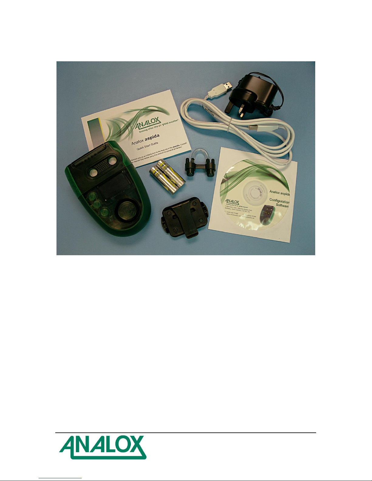
Package Contents Checklist.................................................................................................................... 4
About the Product.................................................................................................................................... 5
Sensor Options Available ................................................................................................................ 5
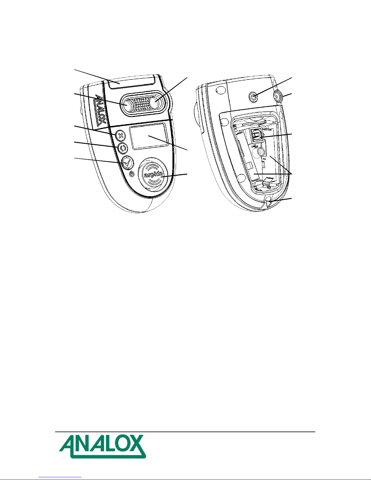
aspida Main Features ..................................................................................................................... 6
Installation of the Product........................................................................................................................ 7
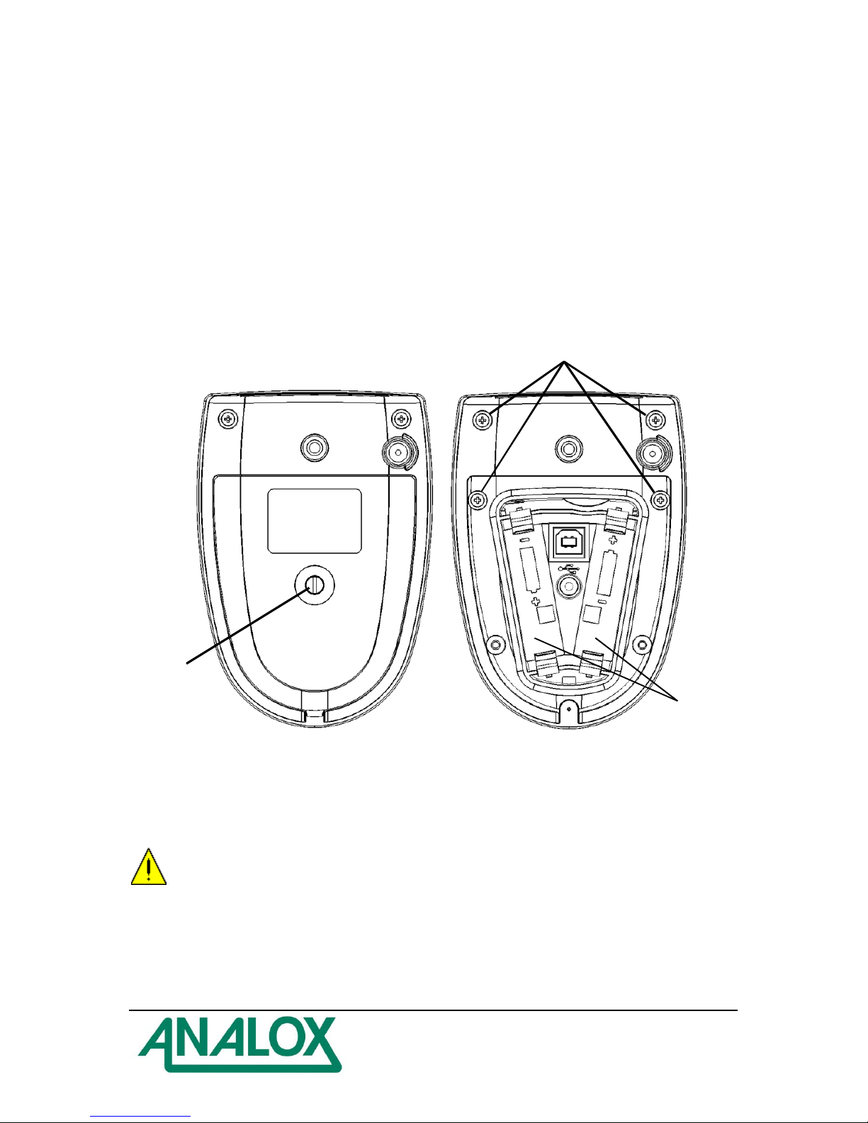
Battery installation ........................................................................................................................... 7
Charging the Analox aspida ........................................................................................................... 8
Operation................................................................................................................................................. 9
Button functions............................................................................................................................... 9
Switching the device on/off.............................................................................................................. 9
User registration............................................................................................................................... 9
The main display............................................................................................................................ 10
Battery status................................................................................................................................. 10
Menus............................................................................................................................................ 11
Common menu items..................................................................................................................... 11
Gas alarms..................................................................................................................................... 12
Global alarm options...................................................................................................................... 13
Alarm latching................................................................................................................................ 13
Alarm muting.................................................................................................................................. 13
Data Logging.................................................................................................................................. 14
Man-down alarm............................................................................................................................ 14
Panic Alarm.................................................................................................................................... 14
Time-weighted average (TWA) monitoring of carbon dioxide ....................................................... 15
Maintenance Reminders................................................................................................................ 16
Calibration reminders..................................................................................................................... 16
Sensor replacement reminders...................................................................................................... 16
Faults............................................................................................................................................. 17
Troubleshooting............................................................................................................................. 17
Maintenance.......................................................................................................................................... 18
Calibration...................................................................................................................................... 18
Oxygen fresh air calibration........................................................................................................... 18
Oxygen sensor replacement.......................................................................................................... 20
Cleaning......................................................................................................................................... 26
Specifications ........................................................................................................................................ 27
Warranty information............................................................................................................................. 28
Disposal................................................................................................................................................. 29
WEEE statement ........................................................................................................................... 29
Oxygen sensor disposal ................................................................................................................ 29
Declaration of Conformity...................................................................................................................... 30

aspida –User Manual
Document Ref: PGA-801-10 - December 2014
Page 3
Safety Information
WARNING: Read the safety information fully before using the aspida.
High volume audible alarm
The aspida employs high volume warning alarms with a sound pressure level of 95dB in the case of
normal gas alarms, and up to 110dB in the case of the man-down alarm. Care should be taken
particularly when the man-down feature is enabled to minimise exposure to the sounder. The aspida
unit should always be worn away from the head in order to minimise close range exposure to the
alarm.
WARNING: The 110dB man-down alarm can be manually activated at any time by holding the
button. Care should be taken not to activate this alarm when the aspida unit is in close
proximity to the ears.
Electrochemical oxygen sensor
The oxygen sensor used in certain aspida options is an electrochemical sensor which contains toxic
compounds. Under normal conditions the sensor will be safely sealed. To prevent leakage, the unit
must not be exposed to temperatures outside the specified range, or be exposed to organic vapours,
which may cause physical damage to the body of the sensor. The unit must not be stored in areas
containing organic solvents or in flammable liquid stores.
WARNING: Read the safety information fully before using the aspida.
Sensor faults
If the unit indicates a fault the user is no longer protected and should evacuate from areas used to
store CO2

aspida –User Manual
Document Ref: PGA-801-10 - December 2014
Page 4
Package Contents Checklist
a) Analox aspida main unit
b) 2xAA rechargeable batteries
c) Belt clip attachment
d) Charger power supply
e) USB communication cable
f) Software disc
g) Quick start manual
h) Calibration adapter

aspida –User Manual
Document Ref: PGA-801-10 - December 2014
Page 5
About the Product
The Analox aspida is a portable, personal, gas detection instrument capable of detecting potentially
dangerous ambient levels of oxygen and carbon dioxide for protection of people working in confined
spaces. The instrument gives clear audible, visible and vibration warning of potentially dangerous gas
levels. A high resolution Organic Light-Emitting Diode (OLED) display shows clear, live gas level
readings in all light conditions.
The Analox aspida is housed in a robust, IP65 splash proof enclosure and is designed to attach
securely and comfortably to clothing. The instrument operates using rechargeable battery technology,
allowing it to run for more than 12 hours continuously between charges. The Analox aspida allows
for easy replacement of the rechargeable batteries with standard, AA, non-rechargeable batteries in
circumstances where recharging is not possible.
As an additional safety feature, the Analox aspida provides an optional man-down/panic alarm
feature, designed to give a lone-worker peace of mind when working in enclosed areas. When
enabled with this feature, the aspida monitors the user’s movements and sounds an ultra-loud siren
if they should become incapacitated. In addition, a user-activated panic feature can initiate the ultra-
loud siren to signal for help.
Additional feature of the Analox aspida include time-weighted average monitoring of carbon dioxide
levels, multiple user registration for shared devices and a continuous 7 day internal data log. All
features are fully configurable through USB using the Analox aspida Intelligent Configuration
Software.
Sensor Options Available
The Analox aspida is available in three sensor configurations:
a) Carbon dioxide –single sensor
b) Oxygen –single sensor
c) Carbon dioxide and oxygen - dual sensor

aspida –User Manual
Document Ref: PGA-801-10 - December 2014
Page 6
aspida Main Features
1
2
3
4
5
6
7
8
11
13
9
10
12
Figure 1 - Main features
1) Alarm, fault and OK LEDs
2) Carbon dioxide gas port (if sensor fitted)
3) Cancel/exit/panic-alarm button
4) Cycle button
5) Confirm/on/off button
6) Oxygen gas port (if sensor fitted)
7) OLED display
8) Horn
9) Belt loop mount
10) Charger socket
11) USB communication socket
12) Battery compartments
13) Lanyard pin

aspida –User Manual
Document Ref: PGA-801-10 - December 2014
Page 7
Installation of the Product
Before using the Analox aspida, batteries should be inserted into the instrument. If using the
rechargeable batteries provided, it should be given a full charge cycle. A full charge cycle will be
complete within approximately 4.5 hours.
Battery installation
The Analox aspida is powered by a pair of standard AA batteries. The device can be powered using
the NiMH re-chargeable batteries included in the product package or using a pair of standard Alkaline,
non-rechargeable batteries.
To gain access to the battery compartment, undo the screw in the centre of the battery cover on the
rear of the device and lift the cover off. Before removing batteries from the device, ensure that it is
switched off and that the mains charger and USB cable are disconnected.
1
2
3
Figure 2 - Battery compartment
1) Battery compartment access screw
2) Sensor compartment access screws
3) Battery compartments
WARNING: Care should be taken when inserting batteries, paying particular attention to the
orientation of each battery. Markings on the inside of the battery compartment indicate the
correct battery orientation. Incorrect orientation of the batteries may result in damage to the
device. Batteries should be inserted by hand without use of tools.

aspida –User Manual
Document Ref: PGA-801-10 - December 2014
Page 8
Charging the Analox aspida
WARNING: The following safety warnings should be observed before attempting to charge
the Analox aspida:
The Analox aspida should only be charged when the NiMH batteries supplied with the
product are fitted. Attempting to recharge non-rechargeable alkaline batteries will in most
cases result in an aborted charge, and this will be indicated by a flashing icon on the
display. However, connecting the mains charger whilst using alkaline batteries is not
recommended and may result in damage to the device.
The Analox aspida may be used with standard rechargeable AA batteries which have been
charged using a third-party charging device. However, only NiMH batteries provided by
Analox should be used when attempting to charge batteries within the device using the mains
charger.
Do not attempt to charge the device using a mains charger other than the one supplied with
the device. Use of an incorrect mains charger may damage the device.
The battery cover should always be securely fitted before performing a charge.
With the mains charger disconnected from the wall outlet, insert the power jack into the socket
on the rear of the aspida device.
Insert the mains charger into the wall outlet.
Switch on the mains outlet.
NOTE: The unit can be charged whilst switched on or switched off.
The following lists the conditions that may be observed during a charge.
Battery icon state
Audible warning
Charge status
>> (animated)
None
Charging (charge setup)
>> >> (animated)
None
Charging
>> (animated)
None
Charging (approx. 1.5 hours
remain)
Success beep
Charge complete
(flashing)
Fault beep
Charge fault
Fault beep
No batteries
NOTE: If an attempt is made to charge non-rechargeable batteries, a fault will be indicated by a
flashing icon.
The normal charge period for a set of flat batteries is approximately 4.5 hours.
WARNING: During charging, the device will warm up. This effect is normal. It is however
suggested that the device is charged indoors at room temperature to ensure a full charge
cycle completes.

aspida –User Manual
Document Ref: PGA-801-10 - December 2014
Page 9
Operation
Button functions
The Analox aspida has three buttons that are used as follows:
Button
Function
Power on/off
Confirm
Select button
Show device menu
Cycle through options
Cancel
Return to main screen
Switching the device on/off
To switch the Analox aspida on, press the button.
After a few seconds, the main gas display screen will be shown. If multiple user-names are registered
to the device then the user-name selection screen will be shown instead. See the section ‘User
registration’for further instructions.
On start-up, the sensors have a short warm-up period. Live gas values will not be displayed until the
sensors have completed their warm-up. For oxygen, the warm-up takes 15 seconds. For carbon
dioxide, the warm-up takes 30 seconds. Sensor warm-up will be shown on the display.
To switch off the device, press and hold the button until the screen goes blank then release the
button.
User registration
The Analox aspida allows for registration of up to two usernames. This allows multiple users to
share use of the device. On start-up, a username is selected, and all subsequent gas information is
logged internally against the selected user ID. Users can be registered to a device using the aspida
configuration software. See the aspida configuration software for instructions.
On device power up, if a single user is registered, the username will be displayed for a few seconds,
after which the device will operate normally.
If 2 users are registered, both usernames will be displayed in a menu for the user to select. Pressing
the button will cycle between highlighted usernames. The button will select the highlighted
user.
NOTE: If a user is not selected within 2 minutes of start-up, a ‘no user’ ID will be selected
automatically and the device will continue to run normally. During this time, a reminder beep will be
sounded to prompt the user to select an ID.

aspida –User Manual
Document Ref: PGA-801-10 - December 2014
Page 10
The main display
Under normal operation, gas values for each of the sensors fitted are shown in their own window
along with the description of the gas type and measurement units. The current gas value for each
sensor will be updated on the display once per second.
Figure 3 - Dual sensor display (left), single sensor display (right)
1) Man-down detection (only shown when the man-down feature is enabled)
2) Clock
3) Measured gas value (dual sensor)
4) Gas type and units (dual sensor)
5) Battery status icon
6) Measured gas value (single sensor)
7) Gas type and units (single sensor)
If the user does not operate any buttons for one minute, the screen-saver will activate showing a logo
which will drift around the display with the screen dimmed. Pressing any button will wake the device
from screen saver mode and display the main gas screen. If the device is connected to the charger or
to a PC via USB, the screen-saver will not activate but the screen will still dim as normal.
NOTE: The screen-saver function is intended to extend the battery life and prevent screen burn-in.
During screen saver mode, gas values are still monitored as normal. Any gas alarm will wake the
display from screen saver immediately and the main gas display will be shown.
Battery status
The battery status icon is shown in the top right hand corner of the display. This icon gives a
representative indication of the power remaining in the batteries. As the batteries run down from full to
empty, the battery icon will be displayed in various states.
Icon
Battery status
,
Battery sufficiently charged
Battery low
(flashing)
Battery near empty. Approx. 1 hour of operation remaining.
A reminder beep will sound periodically.
The device is powered from the mains charger. The icon
will be shown next to the battery icon.
The device is attached to and powered by a computer via
a USB cable. The USB symbol will be shown instead of
the battery icon.
NOTE: Due to the nature of the battery type, the battery status icon may temporarily indicate a
capacity higher than the true remaining battery capacity upon switch-on. This effect is usually seen in
devices which have been switched off for an extended period of time. The true battery status will be
indicated within a few minutes of power-up.

aspida –User Manual
Document Ref: PGA-801-10 - December 2014
Page 11
Menus
The device main menu can be accessed by pressing the button. This will display a menu screen
similar to the one shown below.
Figure 4 - A typical menu
NOTE: The menu icons displayed will vary depending on the configuration of the device and the
sensor fitted.
Press to cycle through the menu options and highlight the chosen option. If an arrow is present at
either end of the menu, it indicates that there are more options beyond the edges of the visible menu.
Advancing the menu cursor past the end of the visible menu will reveal the extra menu items.
Pressing the button when the chosen option is highlighted will select that option.
Pressing at any time whilst the menu is shown will return to the main gas display.
Common menu items
Menu Icon
Function
Information - Selecting this menu item will display a screen with
information related to the specific device, such as serial number and
firmware version.
Back - Selecting back exits the menu and returns to the main gas
display.
Oxygen fresh-air calibration - (oxygen configurations only) Select this
option to perform a fresh-air calibration of the oxygen sensor. This
feature is described in further detail in the section ‘Oxygen fresh air
calibration’ later in this manual.
Carbon dioxide sensor information - (Carbon dioxide configurations
only). This option displays a page which gives information about when
the sensor is next due a calibration.
Oxygen sensor information - (Oxygen configurations only). This option
displays a page which gives information about when the sensor is next
due a calibration and also when replacement of the sensor is due.

aspida –User Manual
Document Ref: PGA-801-10 - December 2014
Page 12
Gas alarms
The Analox aspida has a range of configurable alarms to warn the user of potentially dangerous
atmospheres. For each gas sensor fitted to the device, up to 3 configurable alarms are available. In
the case of carbon dioxide, an extra Time Weighted Average (TWA) alarm is provided. See the
section ‘Time-weighted average (TWA) monitoring of carbon dioxide’for more details.
In the case of an alarm condition being detected, the horn will activate giving an audible warning to the
user. At the same time, the red alarm LEDs will flash.
The device also has a vibrating alert to accompany gas alarms. When an alarm is triggered the unit
will vibrate for 10 seconds after which the vibration will stop. The unit will not vibrate whilst connected
to USB or the charger.
A gas alarm condition will also be shown on the display, giving a clear indication of the gas that has
triggered the alarm. In the case of an alarm, the gas warning symbol will appear below the gas
reading which will be surrounded by a flashing border, as shown below.
Figure 5 - The main gas display showing that carbon dioxide levels have triggered an alarm
Each alarm is configurable as either high-going or low-going. In the case of a high going alarm, if the
gas value exceeds the configurable set-point, the alarm will be activated. The 3 gas alarms are also
ranked in order of priority, so that if a more dangerous level of gas is detected, the user is notified.
Example
Two alarms are configured for detection of oxygen levels.
Priority 1 alarm is configured as a low going alarm with a set-point of 18.0%.
Priority 2 alarm is configured as a low going alarm with a set-point of 19.5%.
If using this setup the detected level of oxygen falls below 19.5%, priority 2 alarm will be activated.
The red LEDs, vibration and horn will all activate, pulsing at a moderate rate, and a visual warning
will be given on screen. The oxygen value will be highlighted and the gas warning symbol
shown below the reading.
If the detected oxygen level falls further so that it is below 18.0%, priority 1 alarm will be activated.
This alarm is of a higher priority than the priority 2 alarm so the urgency of the alarm will be
increased. The LEDs, vibration and horn will begin to pulse more rapidly to indicate that the
severity of the alarm has increased.

aspida –User Manual
Document Ref: PGA-801-10 - December 2014
Page 13
Global alarm options
There are two configurable options which affect all of the Analox aspida's alarms. Muting and
latching options are set using the aspida configuration software. See the aspida configuration
software manual for instructions.
Alarm latching
Sometimes it is useful for a user to be alerted of a harmful gas level, even after level of gas has
dropped to a safe level. The Analox aspida can be configured to use latching alarms so that alarms
triggered by harmful gas levels will not be missed. The latching alarms option can be enabled using
the aspida configuration software.
If the device is configured to use latching alarms then any alarm that is triggered will remain active
until it is acknowledged by pressing the button.
Example
If a high-going alarm is activated by an increasing level of gas, the alarm will continue to
sound even after the gas level has dropped below the alarm set-point. The alarm can be
acknowledged by pressing the button when the gas reading has fallen below the set-point.
In the case of multiple alarms, the highest priority alarm that was triggered will be latched. If
the priority 1 alarm is latched and the gas level drops below the priority 1 set-point, pressing
the button will clear the priority 1 alarm, however, if the gas level is still sufficient to trigger
the priority 2 alarm, the device will continue to alarm at a priority 2 level.
Alarm muting
Sometimes it is desirable to be able to mute the horn or stop the device vibrating when an alarm is
triggered. The Analox aspida provides an option to allow alarms to be muted. The mutable alarms
option can be set using the aspida configuration software.
If the alarm muting option is set on the device, any active alarm can be silenced by pressing the
button whilst in an alarm state. Pressing will deactivate the horn and the vibration. The red LEDs
and the on-screen warning will continue to flash until the alarm condition is cleared by safe levels of
gas. In the case where a lower priority alarm has been muted and a higher priority alarm is triggered,
the alarms will be un-muted.
Example
If a priority 2 alarm is activated and muted and the detected gas level changes so as to
activate a priority 1 alarm, the horn and vibration will re-activate to warn the user of the
increased severity. A muted alarm will not be un-muted in the case where the alarm level
drops to a lower priority.

aspida –User Manual
Document Ref: PGA-801-10 - December 2014
Page 14
Data Logging
The Analox aspida has a built in data-logging facility which will automatically log gas readings for all
fitted sensors whenever the device is active. Readings are logged every 30 seconds to internal
memory. The device is capable of storing over 7 days of continuous data. All data is logged with a
date and time stamp, and if multiple users are registered with the device, each set of readings is
logged against the selected user ID.
The data-log can be downloaded from the device for analysis using the aspida configuration
software. See the aspida configuration software manual for instructions.
Man-down alarm
The Analox aspida is equipped with a man-down alarm. If the man-down alarm feature is enabled
the aspida device will monitor any movement the device is subject to. If the user who is wearing the
alarm is somehow incapacitated, an alarm will be sounded to alert others in the nearby area of the
accident.
NOTE: By default, the feature is disabled. Enabling or disabling the alarm is performed using the
aspida configuration software (see the section on alarm settings for further details).
If the man-down feature is enabled, the device will sound a low volume pre-warning alarm after it
detects no movement over a period of 4 minutes. The pre-warning alarm will sound for a period of 1
minute, during which a simple shaking of the device or pressing the button will reset the alarm
timer. If after this 1 minute period there has still been no movement detected then the device will
activate its ultra loud siren to warn others of the incident. Once the high volume alarm has been
activated, the alarm can only be cancelled by pressing the button. During a man down alarm
condition, following screen will be shown.
Figure 6 - Display shown when the man-down alarm is triggered
WARNING: Care must be taken whilst using the aspida device with the man down alarm
activated. If the device is detached from the user's person and left on a stationary surface, the
man-down condition will be triggered. This can lead to unintentional activation of the very high
volume siren. As this siren sounds in excess of 100dB, this may be potentially harmful to
hearing. To avoid nuisance alarms, the device should be switched off when left unattended.
NOTE: The man-down high volume siren causes a large strain on the aspida’s batteries and as
such, the expected operating period for the device is significantly reduced if the man-down alert is
allowed to run for extended periods of time.
Panic Alarm
In cases where a worker is in distress and still conscious, it is possible to activate the ultra-loud siren
manually. To activate the panic alarm, press and hold the button.

aspida –User Manual
Document Ref: PGA-801-10 - December 2014
Page 15
Time-weighted average (TWA) monitoring of carbon dioxide
Carbon dioxide is toxic to the human body as concentrations increase. Short term exposure to the gas
can be potentially lethal. Longer term exposure to more moderate levels of carbon dioxide can also be
detrimental to health, so health and safety bodies (i.e. UK HSE) define occupational exposure levels
(OEL) for the gas. These OELs provide a recommended safe exposure to carbon dioxide whilst under
working conditions. The occupational exposure levels are based on a calculated time-weighted
average (TWA) level of carbon dioxide in any one 24 hour period. The TWA calculation is based on
average carbon dioxide levels weighted to an assumed standard 8-hour daily working shift.
The Analox aspida has a facility which automatically calculates a TWA value on a per-user basis.
When a user powers on the device and selects a user ID, the Analox aspida begins calculating and
continuously updating that user’s own TWA. The device also takes into account any historic data from
the last 24 hours which is relevant to the selected user. TWA data is logged alongside the actual gas
readings in the internal data log.
NOTE: If no users IDs are registered to the device, the TWA values will all be attributed to a default
user.
An alarm feature is provided which will warn of a high TWA exposure to carbon dioxide. In addition to
the normal 3 available gas alarms per sensor, carbon dioxide sensors have a 4th alarm (priority 4)
which is triggered when the calculated TWA value exceeds the TWA set-point. This alarm is set by
default to the UK HSE recommended OEL for carbon dioxide of 5000ppm (0.5%). When this alarm is
triggered, the red LEDs, vibration and horn warnings will activate as with other gas alarms. In the case
of a TWA alarm, ‘TWA’ will be shown below the carbon dioxide reading on the display, as shown
below. The TWA alarm is the lowest priority alarm and as such will be over-ridden by any gas alarms
triggered by a short term increase in carbon dioxide levels.
Figure 7 - The main gas display showing that to user has exceeded their TWA
exposure to carbon dioxide
As with the standard gas alarms, the TWA alarm can also be fully configured using the aspida
configuration software.

aspida –User Manual
Document Ref: PGA-801-10 - December 2014
Page 16
Maintenance Reminders
The aspida has the ability to track the due dates for the various maintenance tasks that are required
during the products life and will display a warning symbol on the display when a maintenance task is
due. Reminders will be shown for the following tasks.
Sensor calibration due (carbon dioxide and oxygen sensors)
Sensor replacement due (oxygen sensors only)
The due dates for maintenance tasks can be viewed at any time by accessing the sensor information
screen for each sensor by selecting either or from the main menu. An example is shown in
Figure 8.
Figure 8 - Oxygen sensor information
Calibration reminders
When a sensor is due for a re-calibration, the calibration due reminder symbol ( ) will be displayed
flashing below the reading of the sensor that is due calibration, as shown in Figure 9. This symbol will
continue to flash until a calibration has been performed.
Figure 9 - Carbon dioxide calibration due reminder
In the case of an oxygen sensor, the calibration due reminder will be cleared upon a successful fresh
air calibration. In the case of a carbon dioxide sensor, the reminder will only be cleared once a span
and zero calibration have been performed consecutively. See the ‘Calibration’ section of this manual
for details of how to calibrate the sensors.
Sensor replacement reminders
Oxygen sensors will need to be periodically replaced as they deplete. When an oxygen sensor is due
to be replaced, the replacement due reminder icon ( ) will be displayed flashing below the sensor’s
gas reading, as shown in Figure 10. See the ‘Oxygen sensor replacement’ section of this manual for
details of how to replace the oxygen sensor. The sensor replacement reminder can only be reset by
using the aspida configuration software. See the aspida configuration software manual for details
of how to reset the sensor replacement reminder.
Figure 10 - Oxygen replacement due reminder

aspida –User Manual
Document Ref: PGA-801-10 - December 2014
Page 17
Faults
If at any point during operation, the device develops a fault, an audible alarm will be sounded and the
amber LED will flash. A fault will also be indicated by a symbol on the display top bar. If the fault is
related to a particular sensor, the sensor window will show ‘---‘ and the symbol will be shown below
the sensor’s gas reading window, as shown below. A fault alarm can be acknowledged by pressing
the button.
Figure 11 - Display showing a carbon dioxide sensor fault
WARNING: If at any time the GREEN ‘OK’ LED is not flashing and the AMBER ‘FAULT’ LED
is flashing the aspida must not be used and the supplier should be contacted, the user is no
longer protected and should evacuate from areas used to store CO2.
Troubleshooting
Symptom Possible cause
Action
Device does not switch on No batteries, or incorrectly
orientated batteries
Check that batteries are inserted
correctly
Device does not switch on Batteries are flat
Check that the batteries are
inserted correct and are
rechargeable NiMH then
perform a device charge.
Batteries will not charge (
shown flashing)
Batteries may not be
rechargeable type
Check that the batteries fitted
are the rechargeable NiMH
batteries supplied with the
aspida
Batteries will not charge (
shown flashing)
Aged batteries causing a charge
fault
Contact supplier for information
about replacing rechargeable
batteries
Batteries will not charge (
shown)
No batteries fitted
Check that rechargeable
batteries are fitted
Battery charge completes but
battery life is short
Battery aging reduced battery
capacity
Contact supplier for information
about replacing rechargeable
batteries
Flashing symbol underneath
gas reading
The sensor is due a
recalibration
Refer to the section ‘Calibration’
of this manual for instructions
Flashing symbol underneath
oxygen gas reading
The oxygen sensor is due to be
replaced
Refer to the section ‘Oxygen
sensor replacement’ of this
manual for instructions

aspida –User Manual
Document Ref: PGA-801-10 - December 2014
Page 18
Maintenance
Calibration
It is normal that the aspida’s sensor readings will drift over time. It is therefore important that the
sensors are periodically re-calibrated. The regularity of calibration depends upon the sensor.
Carbon dioxide sensors should be calibrated every 12 months.
Oxygen sensors should be calibrated every 2 months.
Oxygen calibration should be performed in fresh air as described in the next section. Carbon dioxide
calibration should be performed using the aspida calibration kit and aspida configuration software.
See the aspida configuration software user manual for instructions for calibrating a carbon dioxide
sensor.
Oxygen fresh air calibration
Due to the nature of the electrochemical technology of the oxygen sensor in the Analox aspida, the
sensor output will drift over time. To allow the calibration of the oxygen monitor to be adjusted without
the need to apply a full zero and span calibration, the aspida has a function which allows the user to
span calibrate oxygen monitoring in fresh air. This feature is only available on devices where an
oxygen sensor is fitted.
WARNING: The fresh air calibration of oxygen is only intended to be performed in ambient
air. The calibration assumes an atmospheric oxygen concentration of 20.9%. The fresh air
calibration should not be performed indoors.
To perform an oxygen fresh air calibration:
1) Take the Analox aspida outdoors into fresh ambient air. (If moving the device outdoors
exposes it to a sharp temperature change it is recommended that the device be allowed 5
minutes to allow the temperature of the device to stabilize.)
2) Hold the device at arm’s length throughout the calibration procedure to ensure that breathing
on the sensor inlets does not affect the calibration.
3) Press the button to access the device menu.
4) Highlight the icon and press .
5) The following confirmation screen will be presented. Press to begin the calibration or press
to cancel.
Figure 12 - Oxygen fresh air calibration confirmation screen
6) The unit will now sample the ambient air for 30 seconds to detect a stable oxygen reading.
The progress of the sampling will be displayed on screen as shown below.
Figure 13 - Calibration progress

aspida –User Manual
Document Ref: PGA-801-10 - December 2014
Page 19
7) When the sampling process has complete, an audible alert will be given and the calibration
confirmation screen will be shown as below.
Figure 14 - Oxygen fresh air calibration failed
Figure 15 - Oxygen fresh air calibration passed
8) If the calibration passed then the tick icon will be shown. The new calibration information will
then be stored to the device memory and the device is ready for use. Press the button to
confirm the operation and return to the main screen.
9) If a stable oxygen reading cannot be detected then the confirmation screen will show a cross
icon. Press the button to acknowledge the failed calibration. A failed calibration will leave
the previous oxygen calibration unchanged. To attempt the calibration again repeat steps 3 –
8.
10) Once calibrated successfully, the calibration due date for the oxygen sensor will be reset. The
next calibration due reminder will occur in 2 months.
NOTE: If an oxygen fresh air calibration is started accidentally, the operation can be cancelled at any
time during its sampling stage by pressing the button. This will sound an audible fail beep and the
calibration failed screen will be displayed. Press the button to acknowledge the failure and return
to the main screen.

aspida –User Manual
Document Ref: PGA-801-10 - December 2014
Page 20
Oxygen sensor replacement
Due to the electrochemical nature of the oxygen sensor used in certain aspida configurations, the
sensor output will deplete over time, the expected life of the sensor is 2 years ( With a 1 year
warranty), depending on usage. After a 2 year period of service, or when the sensor has depleted, the
oxygen sensor should be replaced with a fresh sensor. (Contact supplier for a replacement sensor).
WARNING: Before replacing the sensor, disconnect from any USB cable or charger, switch
the device off, open the battery compartment and remove the batteries from the device.
To replace the oxygen sensor:
1) Remove the top 4 screws (see Figure 2) from the device using a cross-head screwdriver as
shown in Figure 16.
Figure 16- Remove the sensor cap screws
2) Gently remove the sensor cap as shown in Figure 17.
Figure 17 - Remove the sensor cap
Table of contents
Popular Laboratory Equipment manuals by other brands

Tecno-gaz
Tecno-gaz ONYX B 5.0 Instructions for use

Koehler
Koehler K44100 Operation and instruction manual

Thermo Scientific
Thermo Scientific 180 Series Operating and maintenance manual

Agilent Technologies
Agilent Technologies 7890A Troubleshooting

Themis
Themis TS-500 quick guide

Biomega
Biomega BioClave Operation manual

PCE Instruments
PCE Instruments PCE-DPS 25 quick start guide

BioCare Medical
BioCare Medical Desert Chamber Pro manual

Family Care Accu
Family Care Accu BBW-9600 user manual

Forma Scientific
Forma Scientific 3940 Operating and maintenance manual

VERDER
VERDER Carbolite Gero AX 60 Installation, operation and maintenance instructions

CORNING
CORNING MicroDEN instruction manual