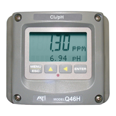
Analytical Technology Q46/85 User manual

ModelQ46/85
PeraceticAcid
Measurement
System
Operation and Maintenance
Manual
HomeOfficeEuropeanOffice
AnalyticalTechnology,Inc.ATI(UK) Limited
6Iron BridgeDriveUnit 1&2GateheadBusiness Park
Collegeville, PA 19426Delph NewRoad, Delph
SaddleworthOL3 5DE
Ph: 800-959-0299Ph: +44(0)1457-873-318
610-917-0991
Fax: 610-917-0992Fax: + 44(0)1457-874-468
Email: sales@analyticaltechnology.comEmail:sales@atiuk.com

PRODUCT WARRANTY
AnalyticalTechnology,Inc.(Manufacturer) warrantstothe Customerthatifanypart(s)
ofthe Manufacturer'sproductsprovestobe defectiveinmaterialsorworkmanship
withinthe earlierof18 monthsof the dateof shipmentor12monthsof the dateofstart-
up,suchdefectivepartswillbe repaired orreplacedfreeofcharge.Inspectionand
repairstoproductsthoughttobe defectivewithinthewarrantyperiodwillbe completed
atthe Manufacturer's facilitiesinCollegeville,PA. Productson whichwarrantyrepairs
arerequired shall be shippedfreight prepaidtothe Manufacturer. The product(s)willbe
returnedfreightprepaidandallowed ifitisdeterminedbythe manufacturerthatthe
part(s)failed duetodefectivematerialsorworkmanship.
Thiswarrantydoesnotcoverconsumableitems,batteries,orwearitemssubjectto
periodicreplacement includinglampsand fuses.
Gassensors,exceptoxygen sensors,arecovered bythiswarranty,butaresubjectto
inspectionforevidenceofextended exposuretoexcessivegasconcentrations.Should
inspectionindicatethatsensorshavebeen expended ratherthan failed prematurely,the
warrantyshall not apply.
TheManufacturerassumesno liabilityforconsequentialdamagesofanykind,and the
buyerbyacceptanceofthisequipmentwill assumeall liabilityforthe consequencesof
itsuseormisusebytheCustomer,hisemployees,orothers.Adefectwithinthe
meaningofthiswarrantyisanypartofanypieceofaManufacturer's productwhich
shall,when suchpartiscapableofbeingrenewed,repaired,orreplaced,operateto
condemnsuchpieceofequipment.
Thiswarrantyisinlieu ofall otherwarranties(includingwithoutlimitingthe generalityof
the foregoingwarrantiesofmerchantabilityand fitness foraparticularpurpose),
guarantees,obligationsorliabilitiesexpressed orimpliedbythe Manufacturerorits
representativesandbystatuteorruleof law.
Thiswarrantyisvoidifthe Manufacturer's product(s)hasbeen subjecttomisuseor
abuse,orhasnotbeen operated orstoredinaccordancewithinstructions,orifthe
serialnumberhasbeenremoved.
AnalyticalTechnology,Inc.makesnootherwarrantyexpressed orimpliedexceptas
statedabove.

2
O&M Manual
RevF(8/17)
Table of Contents
PART1- INTRODUCTION................................. 4
1.1 General...................................................... 4
1.2 Standard System....................................... 5
1.3 Features..................................................... 8
1.4 Q46/85 SystemSpecifications.................. 9
1.5 Q46HPerformance Specifications...........11
PART2–ANALYZERMOUNTING.................12
2.1 General.....................................................12
2.2 Wall or PipeMount..................................13
2.3 Panel Mounting........................................15
PART3–SENSOR/FLOWCELLMOUNTING16
3.1 General.....................................................16
3.2 Constant-HeadFlowcell...........................16
3.3 SealedFlowcell........................................17
3.4 SubmersionMounting..............................19
PART4–ELECTRICALINSTALLATION......20
4.1 General.....................................................20
4.2 Power Connection....................................21
4.4 Direct Sensor Connection ........................25
4.5 SensorWiring ......................................26
4.6 JunctionBoxConnection.........................27
PART5–SENSORASSEMBLY.........................28
5.1 PAASensor Preparation..........................28
5.2 Optional pHSensor..................................30
PART6–CONFIGURATION.............................31
6.1 User Interface...........................................31
6.11 Keys.........................................................32
6.12 Display.....................................................32
6.2 Software...................................................34
6.21 SoftwareNavigation...............................34
6.22 MeasureMenu [MEASURE]...................37
6.23 CalibrationMenu [CAL].............................38
6.24 ConfigurationMenu[CONFIG]..............39
6.25 ControlMenu[CONTROL]....................45
6.26 DiagnosticsMenu[DIAG].........................50
PART7–CALIBRATION...................................55
7.1 PAACalibration......................................55
7.11 PAAZero Cal..........................................55
7.12 PAASpanCal..........................................56
7.2 TemperatureCalibration ..........................58
7.3 pHCalibration..........................................59
7.31 Two-PointpHCal....................................59
7.32 One-PointpHCal.....................................60
PART8–PIDCONTROLLERDETAILS.........62
8.1 PIDDescription.......................................62
8.2 PIDAlgorithm.........................................62
8.3 Classical PIDTuning ...............................64
8.4 ManualPIDOverrideControl..................65
8.5 CommonPIDPitfalls...............................65
PART9–SYSTEMMAINTENANCE................67
9.1 General.....................................................67
9.2 Analyzer Maintenance.............................67
9.3 PAASensor Maintenance........................67
9.31 Sensor AcidCleaning..............................68
9.4 FlowCell Maintenance............................69
PART10 –TROUBLESHOOTING....................70
10.1 General.....................................................70
10.2 External SourcesofProblems..................70
10.3 Analyzer Tests.........................................71
10.4 DisplayMessages....................................72
10.5 Sensor Tests.............................................74
SPAREPARTS......................................................76


3
O&M Manual
RevF(8/17)
Table of Figures
FIGURE 1-TYPICAL SYSTEM DIAGRAM ..........................................................................................5
FIGURE 2-MONITORING SYSTEMW/BAYONET STYLE PHSNSOR ....................................................6
FIGURE 3-SEALED FLOWCELL ASSEMBLIES W/FLOW CONTROL......................................................7
FIGURE 4–Q46 ENCLOSURE DIMENSIONS ..................................................................................12
FIGURE 5-WALLOR PIPE MOUNT BRACKET.................................................................................13
FIGURE 6-WALL MOUNTING DIAGRAM ........................................................................................14
FIGURE 7-PIPE MOUNTING DIAGRAM..........................................................................................14
FIGURE 8-PANEL MOUNT CUTOUT .............................................................................................15
FIGURE 9-CONSTANT HEAD FLOWCELL DETAILS.........................................................................16
FIGURE 10 -SEALED FLOWCELL DETAILS.....................................................................................17
FIGURE 11 -SEALED PHFLOWCELL DETAILS ...............................................................................18
FIGURE 12 -SUBMERSIBLE SENSOR MOUNTING ASSEMBLY ..........................................................19
FIGURE 13 -LINE POWER CONNECTION .......................................................................................22
FIGURE 14 -OPTIONAL RELAY BOARD WIRING .............................................................................23
FIGURE 15 -OPTIONAL RELAY BOARD WIRING .............................................................................24
FIGURE 16 -OPTIONAL ANALOG OUTPUT WIRING.........................................................................24
FIGURE 17 -SENSOR CABLE PREPARATION .................................................................................25
FIGURE 18 -SENSOR WIRING......................................................................................................26
FIGURE 19 -JUNCTION BOX INTERCONNECT WIRING ....................................................................27
FIGURE 20 -PAA SENSOR ASSEMBLY .........................................................................................28
FIGURE 21 -SUBMERSIBLE PAA SENSOR ASSEMBLY ...................................................................29
FIGURE 22 -USER INTERFACE.....................................................................................................31
FIGURE 23 -SOFTWARE MAP ......................................................................................................36
FIGURE 24 -AUTOMATIC PHBUFFER TABLES...............................................................................44
FIGURE 25 -CONTROL RELAY EXAMPLE,HYSTERSISAND TWOOPPOSITE PHASE OPTIONS ............49
FIGURE 26 -ALARM RELAY EXAMPLE ..........................................................................................49
FIGURE 27 -Q46H ISA (IDEAL)EQUATION...................................................................................63
FIGURE 28 -Q46H DSIAPLY MESSAGES ......................................................................................72
FIGURE 29 -DISPLAY MESSAGES (CONTINUED)...........................................................................73
FIGURE 30 -PT100 RTD TABLE ..................................................................................................75

4
O&M Manual
RevF(8/17)
Part 1 - Introduction
1.1General
TheModelQ46/85isan on-line monitoringsystemdesignedforthe continuous
measurementofPeraceticAcid(PAA)concentrationinsolution.Thefull scale
operatingrangeofthe systemmaybe selected bythe userfor0-20.00 ppm,0-
200.0ppm,or0-2000ppm,andthesensingsystemwill operateon water
streamswithtemperaturesrangingfrom0to50°C.TheQ46/85 PAA
MeasurementSystemisengineeredforapplicationsinwhichPAAisappliedto
waterforsterilization purposes
Thebasicsensingelementused inthePAA monitorisapolarographic
membrane sensorwhichmeasuresPAAdirectly.Watersimplyflowspastthe
sensorand directlytodrain,withthe flowrateandpressureacross the sensor
controlledbyaconstantheadflowcell assembly.ThePAAmeasurementdoes
notalterthe sampleoradd anychemicalstothe samplestream,sothe water
flowcan returntothe systemif desired.
Q46/85 Monitorsareavailableintwobasicelectronicversions,a90-260VAC
powered monitor,ora12-24VDC powered monitor–bothwiththree relaysand
two4-20 mAanalogoutputs.Bothversionsallowflexibleoutputoptionswhich
include additional4-20mAcurrentoutputs,additional0-30 VDC signalrelays,
PIDcontrol, and digitalcommunicationcards.

ATI Q46H/85 PAASystemPart 1– Introduction
5
O&M Manual
RevF(8/17)
1.2Standard System
ThestandardmodelQ46/85 systemincludesthreemaincomponents,theQ46
analyzer,aconstanthead flowcell,and aPAA sensor.Alow-volumeflowcell is
alsoavailableforapplicationswheresampleflowrateand pressurecan be
carefullycontrolled.Figure1showsatypicalinstallationincluding the optional
pHsensor.
Forconnectionofthe sensortotheelectronics,a25'cableissupplied.An
additional100feetofinterconnectcablemaybe added using#07-0100junction
box.All required sparepartsarealsoprovided withthe basicsystem,including
sparemembranes,electrolyte, o-rings, and anyspecialhardware.
Figure 1 -TypicalSystemDiagram

ATI Q46H/85 PAASystemPart 1– Introduction
6
O&M Manual
RevF(8/17)
Figure2belowshowsthe samestandardflowcell assemblyandPAA sensor
alongwiththe conventionaltype pHsensor.A specialadapterisrequired tohold
the pHsensorinitsproperlocationinthe flowcell inlet chamber.
Figure 2 -Monitoring Systemw/BayonetStylepH Snsor

ATI Q46H/85 PAASystemPart 1– Introduction
7
O&M Manual
RevF(8/17)
Figure3belowshowsan installation usinga(00-1522)sealedflowcell forthe PAA
sensoranda(00-1527)sealed flowcell forthe pHsensor.Thistype ofinstallation
requirescarefulflowcontrol.Werecommend theuseofour(03-0371)flowcontrol
assemblywhen usingsealed flowcells.Thisassemblyconsistsofanin-line filteranda
fixed-flowregulatorwhichwill maintainaconstant400 cc/minflowratethroughthe
system.Thisflowwill be maintained solongasinletpressuresarebetween 5and 125
PSIG. The in-line filterisused mainlytoprotectthe flowcontrolelementagainstlarger
particlesthatmight causepluggingofthedevice.
Figure 3 -SealedFlowcellAssembliesw/Flow Control

ATI Q46H/85 PAASystemPart 1– Introduction
8
O&M Manual
RevF(8/17)
1.3Features
·StandardQ46HAnalyzershavefullyinputsandoutputs.Analogoutputsare
additionallycompletelyisolatedfromeachother
·Availableineither90-260 VACor12-24VDC powersupplysystems.All features
remainthesameinbothvariations.
·OutputHold,OutputSimulate,OutputAlarm,andOutputDelayFunctions.All
forced changesinoutputconditioninclude bumpless transfertoprovide gradual
returntoon-line signallevelsand toavoidsystemcontrolshocks onbothanalog
outputs.
·Three6ampSPDTrelayoutputsandtwoanalog4-20 mAoutputsarestandard.
Softwaresettingsforrelaycontrolincludesetpoint,deadband,phase,delay,and
failsafe.Anoptional3-relaycardforlowvoltagesignalsisavailabletobringthe
totalto6relays.
·SelectablePIDcontrolleron mainanalogoutput. PIDcontrollercanoperatewith
instrumentconfigured asloop-powertransmitter,orasone ofthe twooutputson
the ACpowered instrument. PIDincludesmanualoperation feature,and
diagnostic“stuck-controller” timerfeatureforrelaynotificationofcontrol
problems.
·Twoanalogoutputsonthe relayversion maybe configured totrack PAA and
temperature,PAA andPAA, orPAA and pH.Both analogoutputscan be
individuallyprogrammed tofail tospecificvalues.
·DigitalcommunicationoptionforProfibus-DP,Modbus-RTU,orEthernet-IP.See
Q46 DigitalCommunicationsManualforSpecifications.
·Diagnosticmessagesprovide acleardescription ofanyproblemwithno
confusingerrorcodestolookup.Messagesarealsoincluded fordiagnosing
calibration problems.
·Quick and easyone-pointcalibrationmethodand sensorzero-cal.Toprovide
highaccuracy,all calibration methodsinclude stabilitymonitorsthatcheck
temperatureand mainparameterstabilitybeforeacceptingdata.
·Securitylock featuretopreventunauthorized tamperingwithtransmittersettings.
All settingscanbeviewed whilelocked,buttheycannot bechanged.

ATI Q46H/85 PAASystemPart 1– Introduction
9
O&M Manual
RevF(8/17)
1.4Q46/85 SystemSpecifications
DisplayedParameters Maininput, 0.01 ppmto2000 ppm
Sensortemperature,-10.0to55.0°C (23 to131 ºF)
Sensor Current, 0.0–999.9nA, 0.000to99.99uA
Loop current, 4.00 to20.00 mA
Sensor slope/offset
Modelnumberand softwareversion
PIDController Status
OptionalpH Input value.0.00 to14.00 pH
MainParameterRanges Manualselection of one ofthe followingranges,
0.00 to20.00 ppm
0.0to200.0ppm
0to2000 ppm
Display 0.75”(19.1mm) high4-digitmaindisplaywithsign
12-digit secondarydisplay, 0.3"(7.6mm)5x7dotmatrix.
IntegralLED back-lightfor visibilityinthe dark.
Weight Approximately5lbs.(2.3Kg) withsensor &flowcell
Ambient Temperature Analyzer Service, -20 to60 °C (-4to140 ºF)
Sensor Service,-5to55°C(23 to131°F)
Storage,-5to70°C (-22to158 ºF)
Ambient Humidity 0to95%, non-condensing
EMI/RFIInfluence Designed toEN 61326-1, CE Marked
OutputIsolation 600 Vgalvanicisolation
Filter Adjustable0-9.9minutesadditionaldamping to90%step
input
TemperatureInput Pt100 RTDwithautomaticcompensation
Sensor 2-electrodepolarographicmembranesensorfordirect
measurement of PAA,
SensorMaterials PVC and PEEK
ElectricalCertification OrdinaryLocation,cCSAus (CSA and ULstandards -both
CSA approved), pollutiondegree2,installation category2
SensorCable 25 ft.(7.5meter)cablewith6-pinplug.

ATI Q46H/85 PAASystemPart 1– Introduction
10
O&M Manual
RevF(8/17)
Max.Sensor-to-Analyzer 100 feet(30.5meters), withjunction box
Distance
FlowCell Constanthead overflow,clear cast acrylic, 7-30GPH, 15
GPH recommended,inlet is¼”hosebarbat1/8”MNPT,
outlet is½” hosebarbat 3/8”MNPT
Power 90 -260 VAC,50-60Hz, 10 VA maxor
12-24 VDC,500 mAmax.
Enclosure NEMA4X(IP-66),polycarbonate, stainless steel hardware,
weatherproofandcorrosion resistant,
Mounting Options Wall orpipe mountbracketstandard.Bracketsuitablefor
either 1.5”or2”I.D. U-Boltsfor pipemounting.
Panelmountadapter optional.
Conduit Openings Five½” NPTopenings, Adaptercan beremoved to
provide a1” NPTopening inthebottom ofthe enclosure.
Gland sealsprovided butnotinstalled.
Relays, Electromechanical: Three SPDT,6amp@250 VAC, 5amp@24VDC
contacts.Softwareselection for setpoint, phase, delay,
deadband, hi-loalarm, and failsafe. A-Bindicatorson main
LCD, and Cindicatoron lower display.
OptionalRelays: Three additionalnon-isolated lowpower relaysavailable.
SPST,1Amp@30 VDC.
Analog Outputs Two4-20 mAoutputs.Outputone programmablefor PPM
PAA or PID.Output 2programmableforPPMPAAor
Temperature.Maxload 500 Ohmsfor eachoutput.
Outputsgroundisolated and isolated from each other.An
additional3rd analogoption isavailable.

ATI Q46H/85 PAASystemPart 1– Introduction
11
O&M Manual
RevF(8/17)
1.5Q46HPerformanceSpecifications
Accuracy 0.5%of selectedrangeor 0.02 PPM
Repeatability 0.3%of selectedrangeor 0.01 PPM
Sensitivity 0.05%of selectedrange
Non-linearity 0.1%of selectedrange
Warm-up Time 3secondstorated performance (electronics only)
SupplyVoltageEffects ± 0.05%span
InstrumentResponse Time 60 secondsto90%of step input at lowest damping
Equipmentbearingthismarkingmaynotbe discardedby
traditionalmethodsinthe EuropeancommunityafterAugust12
2005perEUDirective2002/96/EC.Endusersmustreturnold
equipment tothe manufacturerforproperdisposal.

12
O&M Manual
RevF(8/17)
Part 2 – AnalyzerMounting
2.1General
All Q46 Seriesinstrumentsoffermaximummountingflexibility.Abracketis
includedwitheachunitthatallowsmountingtowallsorpipes.Inall cases,
choosealocation thatisreadilyaccessibleforcalibrations.Alsoconsiderthatit
maybe necessarytoutilizealocation wheresolutionscanbeused duringthe
calibration process.Totakefull advantageofthe highcontrastdisplay,mount
the instrumentinalocation wherethe displaycan be viewed fromvariousangles
and longdistances.
Locatethe instrumentincloseproximitytothe pointofsensorinstallation -this
will alloweasy access duringcalibration.Thesensor-to-instrumentdistance
shouldnotexceed 100feet. Tomaximizesignal-to-noiseratiohowever,work
withthe shortestsensorcablepossible.Thestandardcablelengthofthe PAA
sensoris25feet.
Due tothe flexibilityofthe instrumentdesign,someofthemountingfeatures
changebased on the configuration thatwasordered.Forexample,the2-wire
transmitterversion isdifferentforthe115/230VACcontrollerbecausethe rearof
the enclosureismuchdeeperwhen the ACpowered unit isused. Inaddition, the
ACpowered unithasan integrated panelmountflangerequiring asinglecutout
forflushmounting.
Figure 4 – Q46 EnclosureDimensions

ATI Q46H/85 PAASystemPart 2– AnalyzerMounting
13
O&M Manual
RevF(8/17)
2.2Wallor PipeMount
APVCmountingbracketwithattachmentscrewsissuppliedwitheach
transmitterasshowninFigure5.The multi-purposebracketisattachedtothe
rearoftheenclosureusingthe fourflathead screws.Theinstrumentisthen
attachedtothewall usingthe fouroutermountingholesinthebracket. These
holesareslotted toaccommodatetwosizesofu-boltthatmaybe used topipe
mountthe unit. Slotswill accommodateu-boltsdesigned for1½“or2”pipe.
Theactualcentertocenterdimensionsforthe u-boltsareshowninthe drawing.
Notethattheseslotsareforu-boltswith¼-20 threads.The1½” pipe u-bolt(2”
I.D.clearance)isavailablefromATIintype 304 stainlesssteelunderpart
number(47-0005).
Figure 5 -Wall orPipe mount Bracket

ATI Q46H/85 PAASystemPart 2– AnalyzerMounting
14
O&M Manual
RevF(8/17)
Figure 6 -WallMounting Diagram
Figure 7 -PipeMounting Diagram

ATI Q46H/85 PAASystemPart 2– AnalyzerMounting
15
O&M Manual
RevF(8/17)
2.3Panel Mounting
Panelmountingusesthe panelmountingflangemoldedintothe rearsection of
the enclosure.Figure8providesdimensionsforthepanelcutoutrequired for
mounting.
Thepanelmountingbracketkitmustbe ordered separately(partnumber05-
0094).Thiskitcontainsametalretainerbracketthatattachestothe rearofthe
enclosure,4screwsforattachmentofthisbracket, and asealinggaskettoinsure
thatthe panelmountedmonitorprovidesawatertightsealwhen mountedtoa
panel.
Thesealinggasket mustfirst beattachedtothe enclosure. Thegasket contains
an adhesiveonone side sothat it remainsinplaceon theenclosure. Remove
the protectivepaperfromthe adhesiveside ofthegasketandslidethe gasket
overthe back of theenclosuresothat theadhesiveside linesupwiththe back of
the enclosureflange. Onceinplace, you can proceedtomount the monitorin
the panel.
Figure 8 -PanelMount Cutout

16
O&M Manual
RevF(8/17)
Part 3–Sensor/Flowcell Mounting
3.1General
Selectalocation withinthe maximumsensorcablelengthformountingofthe
sensorflowcell.
3.2Constant-HeadFlowcell
PAA sensorsarebestused inaconstant-head overflowchamberbecause
variationsinsampleflowrateand pressurecan causeunstablereadings.When
monitoringlowconcentrations(below0.5PPM),thismethodshouldalwaysbe
used.Mechanicalinstallation ofthe flowcell requiresthatitbe mounted toawall
orotherconvenientflatsurface.Alternatively,the mountingholeson theplate
will accommodatea2" U-boltformountingtheplatetoa2"pipe.Figure9shows
the dimensionsandmountingholelocationsfortheflowcell.Be suretoallow
enoughclearanceon the left sideoftheflowcell forinsertionand removalofthe
sensor. About12 inchesclearanceisrecommended.
Figure 9 -Constant HeadFlowcell Details

ATI Q46H/85 PAASystemPart 3– Sensor/Flowcell Mounting
17
O&M Manual
RevF(8/17)
Oncemounted,inletand drainconnectionsmustbe made.The flowcell
containsa1/8"MNPTinletconnection anda3/8"MNPTdrainconnection.Hose
barbsfortheinletanddrainconnectionsaresupplied withthe flowcellforuse
withflexibletubing.The inlethosebarbisused with¼"I.D.tubingand the drain
hosebarbisusedwith½"I.D. tubing.
3.3SealedFlowcell
Applicationswherethesampleinletflowiswell controlled can useasimpler
sealed flowcell.Using thisflowcell requiresthatflowbe controlled externallyto
about400 cc/min.Variableflowrateorvariablepressurewill causeunstable
readingsinthisflowcell.ATIoffersaspecialflowcontrolelementthatcanbe
used aheadofthisflowcellon the incomingsampleline.The flowcontrolispart
no.(55-0048).It will controltheinletflowrateat400cc/min.withinletpressure
variationsfrom5-150PSIG. A50 micron y-straineraheadofthe flowcontrol
elementisrecommended.The sealedflowcell providesadrainventwithcheck
valvetoavoidpullingavacuumon the flowchamber.
Figure 10 -SealedFlowcell Details

ATI Q46H/85 PAASystemPart 3– Sensor/Flowcell Mounting
18
O&M Manual
RevF(8/17)
Figure 11 -SealedpH Flowcell Details

ATI Q46H/85 PAASystemPart 3– Sensor/Flowcell Mounting
19
O&M Manual
RevF(8/17)
3.4Submersion Mounting
Someapplicationsaremucheasierdoneusingthe submersiblesensor.This
method can sometimesbe usedwhereflowisreasonablyconstant, and hydraulic
headdoesnotvaryappreciably.PAA sensorscan neverbe used incompletely
stagnantconditions.Aflowvelocityofatleast0.3feetpersecondisnormally
required formeasurement. AnyapplicationsforasubmersiblePAAsensor
shouldfirst bediscussed withATI. A trialofsuchinstallationsmaybe necessary.
Submersiblesensorsaremounted toa1"pipeusingastandard1" PVCthread
bythread pipe coupling. Themountingpipecan besecured tostandard1½"
pipe rail usingamountingbracket kitavailablefromATI (part number00-0628)
asshowninFigure12 - Submersible Sensor MountingAssembly
.
SENSOR CABLE
2"HANDRAIL
1"ALUMINUM CONDUIT, THREADED1"T xT PVC COUPLING
ONE END OR 1"SCHED 80 PVC PIPE
LENGTH AS REQUIRED
(SUPPLIED BYCUSTOMER)
SWIVEL MOUNTING BRACKET WITH
HARDWARE, SUPPLIED BYATI
SUPPLIED BYATI
SENSOR, TYPICAL
2 - 3 FT. SUBMERGENCE
Figure 12 -SubmersibleSensorMounting Assembly
Table of contents
Other Analytical Technology Measuring Instrument manuals

Analytical Technology
Analytical Technology Q46H/62-63 User manual

Analytical Technology
Analytical Technology Q25R User manual

Analytical Technology
Analytical Technology Q46H/62 User manual

Analytical Technology
Analytical Technology OL50LL User manual

Analytical Technology
Analytical Technology Q46H/79PR User manual

Analytical Technology
Analytical Technology PQ45H User manual

Analytical Technology
Analytical Technology Q45C2 User manual

Analytical Technology
Analytical Technology A15 User manual

Analytical Technology
Analytical Technology Q46F/82 User manual

Analytical Technology
Analytical Technology Q46F/D User manual