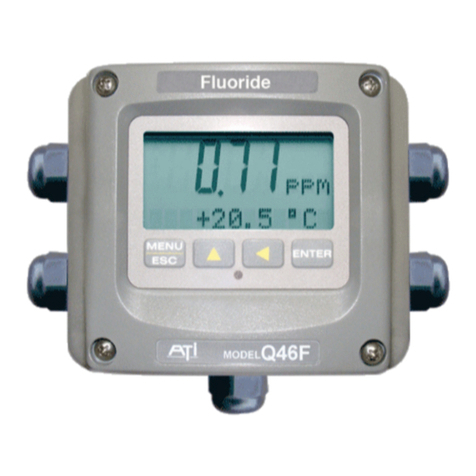
Analytical Technology Q46F/D User manual

ModelQ46F/82
Direct Fluoride
Monitor
HomeOfficeEuropeanOffice
AnalyticalTechnology,Inc.ATI(UK) Limited
6Iron BridgeDriveUnit 1&2GateheadBusiness Park
Collegeville, PA 19426Delph NewRoad, Delph
SaddleworthOL3 5DE
Ph: 800-959-0299Ph: +44(0)1457-873-318
610-917-0991
Fax: 610-917-0992Fax: + 44(0)1457-874-468
Email: sales@analyticaltechnology.comEmail:sales@atiuk.com

PRODUCT WARRANTY
AnalyticalTechnology,Inc.(Manufacturer) warrantstothe Customerthatifanypart(s)
ofthe Manufacturer'sproductsprovestobe defectiveinmaterialsorworkmanship
withinthe earlierof18 monthsof the dateof shipmentor12monthsof the dateofstart-
up,suchdefectivepartswillbe repaired orreplacedfreeofcharge.Inspectionand
repairstoproductsthoughttobe defectivewithinthewarrantyperiodwillbe completed
atthe Manufacturer's facilitiesinCollegeville,PA. Productson whichwarrantyrepairs
arerequired shall be shippedfreight prepaidtothe Manufacturer. The product(s)willbe
returnedfreightprepaidandallowed ifitisdeterminedbythe manufacturerthatthe
part(s)failed duetodefectivematerialsorworkmanship.
Thiswarrantydoesnotcoverconsumableitems,batteries,orwearitemssubjectto
periodicreplacement includinglampsand fuses.
Gassensors,exceptoxygen sensors,arecovered bythiswarranty,butaresubjectto
inspectionforevidenceofextended exposuretoexcessivegasconcentrations.Should
inspectionindicatethatsensorshavebeen expended ratherthan failed prematurely,the
warrantyshall not apply.
TheManufacturerassumesno liabilityforconsequentialdamagesofanykind,and the
buyerbyacceptanceofthisequipmentwill assumeall liabilityforthe consequencesof
itsuseormisusebytheCustomer,hisemployees,orothers.Adefectwithinthe
meaningofthiswarrantyisanypartofanypieceofaManufacturer's productwhich
shall,when suchpartiscapableofbeingrenewed,repaired,orreplaced,operateto
condemnsuchpieceofequipment.
Thiswarrantyisinlieu ofall otherwarranties(includingwithoutlimitingthe generalityof
the foregoingwarrantiesofmerchantabilityand fitness foraparticularpurpose),
guarantees,obligationsorliabilitiesexpressed orimpliedbythe Manufacturerorits
representativesandbystatuteorruleof law.
Thiswarrantyisvoidifthe Manufacturer's product(s)hasbeen subjecttomisuseor
abuse,orhasnotbeen operated orstoredinaccordancewithinstructions,orifthe
serialnumberhasbeenremoved.
AnalyticalTechnology,Inc.makesnootherwarrantyexpressed orimpliedexceptas
statedabove.

2
O&M Manual
Rev-F (8/17)
Table of Contents
PART1- INTRODUCTION................................. 4
1.1 General...................................................... 4
1.2 Q46F/82 SystemSpecifications................ 6
1.3 Q46F/82 Performance Specifications....... 7
PART2–MECHANICALINSTALLATION..... 8
2.1 General...................................................... 8
2.2 Wall MountBracket.................................. 9
2.3 Panel Mount,ACPoweredMonitor ........12
2.4 FlowcellMounting...................................13
2.5 FluorideSensor ........................................14
PART3–ELECTRICALINSTALLATION......15
3.1 General.....................................................15
3.3 Q46FSensor Wiring................................17
3.4 RelayWiring............................................18
PART4–CONFIGURATION.............................20
4.1 User Interface...........................................20
4.11 Keys.....................................................21
4.12 Display.................................................21
4.2 Software...................................................23
4.21 SoftwareNavigation...........................23
4.22 MeasureMenu [MEASURE]...............26
4.23 CalibrationMenu [CAL].........................27
4.24 ConfigurationMenu[CONFIG].........28
4.25 ControlMenu[CONTROL]...............31
4.26 DiagnosticsMenu[DIAG].....................36
PART5–CALIBRATION...................................40
5.1 Calibration ...............................................40
5.11 SlopeAdjustment.................................40
5.12 Single PointCalibration.......................41
5.2 TemperatureCalibration ..........................42
PART6–PIDCONTROLLERDETAILS.........43
6.1 PIDDescription.......................................43
6.2 PIDAlgorithm.........................................43
6.3 Classical PIDTuning ...............................46
6.4 ManualPIDOverrideControl..................46
6.5 CommonPIDPitfalls...............................47
PART7–SYSTEMMAINTENANCE................48
7.1 General.....................................................48
7.2 Analyzer Maintenance.............................48
7.3 Sensor Maintenance.................................48
PART8–TROUBLESHOOTING......................49
8.1 General.....................................................49
8.2 External SourcesofProblems..................49
8.3 Analyzer Tests.........................................50
8.4 DisplayMessages....................................51
SPAREPARTS......................................................52

3
O&M Manual
Rev-F (8/17)
Table of Figures
FIGURE 1–TYPICAL FLUORIDE MONITORING SYSTEM...........................................................5
FIGURE 2-Q46F ENCLOSURE DIMENSIONS.........................................................................9
FIGURE 3-WALL OR PIPEMOUNT BRACKET .......................................................................10
FIGURE 4-WALL MOUNTING DIAGRAM ..............................................................................11
FIGURE 5-PIPE MOUNTING DIAGRAM................................................................................11
FIGURE 6-PANEL MOUNT CUT-OUT .................................................................................12
FIGURE 7-FLUORIDE FLOWCELL.......................................................................................13
FIGURE 8-FLUORIDE SENSOR ..........................................................................................14
FIGURE 9-LINE POWER CONNECTION ...............................................................................16
FIGURE 10 -SENSOR AND CONTROL CONNECTION .............................................................17
FIGURE 11 -RELAY CONTACTS .........................................................................................18
FIGURE 12 -USER INTERFACE ..........................................................................................20
FIGURE 13 -SOFTWARE MAP............................................................................................25
FIGURE 14 -CONTROL RELAY EXAMPLE ............................................................................34
FIGURE 15 -ALARM RELAY EXAMPLE ................................................................................35
FIGURE 16 -Q46 ISA PID EQUATION................................................................................44
FIGURE 17 -Q46 DISPLAY MESSAGES...............................................................................51

4
O&M Manual
Rev-F (8/17)
Part 1 - Introduction
1.1General
TheQ46F/82 DirectFluoride Systemisan on-line monitoringsystemdesigned
forthe continuousmeasurementoffluorideion insolution.Thesystemis
designed tomeasurefluoride ion directlywithouttheuseofchemicalbuffersand
issuitableforpotablewatersystemswithstablepHandconductivity.It is
especiallyusefulforapplicationswherethe useofchemicalsisundesirable.
Thefull scaleoperating rangeofthesystemmaybe selected bythe userfor0-
20.00PPM,0-200.0PPM,or0-2000 PPM.The analogoutputsignalmaybe
spanned forsmallerrangeswithinthe overalloperatingranges.Becausewater
isflowingthroughtheflowcell atalowrate,thisunitcannotbeexposed to
temperaturesbelow0°C.
Thebasicsensingelement used inthemonitorisafluoride ionselective
electrode(ISE).Thissensorcontainsalanthanumfluoride crystalthat generates
avoltageproportionaltotheactivityoffluorideion insolution. A silver/silver
chloride referenceelectrode containedinthe samesensorbodyprovidesthe
secondhalf of themeasurement cell. BecauseISEelectrodesrespond toactivity
ratherthanconcentration, the responseisslightlyaffectedbychangesinsample
pHandconductivity, but theseeffectsarequitesmall onsamplesfromrelatively
stablewatersourcessuchaswell water.
Thefluoride monitoring systemincludes2parts,an electronicdisplayunit(panel
orwall mount)andasensor/flowcell assembly.Atypicalfluoride system
installation isshowninFigure1.The measured fluoride concentration is
displayed onabacklitLCD on the frontoftheinstrument. Two4-20mAoutputs
areprovided forrecordingordataloggingoffluorideconcentration and
temperature.Alarmcontactsarealsostandardintheelectronicpackageand
maybe usedeitherforsimplecontrolschemesorforsignalingoperatorsof
abnormaloperatingconditions.

ATI Q46F/82 Direct Fluoride MonitorPart 1– Introduction
5
O&M Manual
Rev-F (8/17)
Figure 1 – Typical FluorideMonitoring System

ATI Q46F/82 Direct Fluoride MonitorPart 1– Introduction
6
O&M Manual
Rev-F (8/17)
1.2Q46F/82SystemSpecifications
DisplayedParameters Maininput, 0.01 ppmto2000 ppmdissolved fluoride
SensormV
SampleTemperature
Loop current, 4.00 to20.00 mA
Sensor slope &zerooffset
Modelnumberand softwareversion
PIDController Status
MainParameterRanges Manualselection of one ofthe followingranges,
0.00 to20.00 ppm
0.0to200.0ppm
0to2000 ppm
Display 0.75”(19.1mm) high4-digitmaindisplaywithsign
12-digit secondarydisplay, 0.3"(7.6mm)5x7dotmatrix.
IntegralLED back-lightfor visibilityinthe dark.
Ambient Temperature Analyzer Service, 5to40°C(41to104ºF)
Storage,-5to70°C(-22 to158ºF)
Ambient Humidity 0to95%, non-condensing.
EMI/RFIInfluence Designed toEN 61326-1
OutputIsolation 600 Vgalvanicisolation
Filter Adjustable0-9.9minutesadditionaldamping to90%step
input
Sensor Combination F-/Reference IonSelectiveElectrode
SensorMaterials Glass,LanthanumFluoride, Ryton
Interconnect Cable 10 ft.(6.15 meter)standard
Q46FPower: 100-240 VAC ±10%, 50/60 Hz
Optional: 12-24 VDC
Q46FEnclosure: NEMA4X,IP66, polycarbonate,stainlesssteelhardware
HWD:4.9"(124 mm)x4.9"(124mm)x5.5"(139 mm)
Flammabilityrating:UL94 V-0

ATI Q46F/82 Direct Fluoride MonitorPart 1– Introduction
7
O&M Manual
Rev-F (8/17)
Mounting Options Wall mountbracketstandard.
Panelmountadapter optionalforQ46FOnly
Relays, Electromechanical: Three SPDT,6amp@250 VAC, 5amp@24VDC
contacts.Softwareselection for setpoint, phase, delay,
deadband, hi-loalarm, and failsafe.A-Bindicatorson
mainLCD.
LowPowerRelays: Three SPST,1amp@24VDC.Softwareselection for
setpoint,phase, delay, deadband, hi-loalarm, andfailsafe.
Analog Outputs Two4-20 mAoutputs.Outputone programmablefor PPM
F-or PID.Output 2programmableforPPMor
temperature.Maximum load 500 Ohmsforeach output.
Outputsgroundisolated and isolated from each other.
Digital Communications Profibus-DP, Modbus-RTU. Moreversionspending.
(Optional) See Q46DigitalCommunicationsManualfor
Specifications.
SampleFlowrate1GPH Minimum(60 ml/min.)
5GPH Maximum (315ml/min.)
Weight 4lbs.(1.8Kg.)
1.3Q46F/82PerformanceSpecifications
Accuracy +/-0.1PPMor 0.2%of selected range
Repeatability +/-0.05 PPMor 0.1%ofselected range
Sensitivity 0.01 PPM
Non-linearity 0.2%of selectedrange
Warm-up Time 3secondstorated performance (electronics only)
Sensorrequires 1hourstabilization at start-up
SupplyVoltageEffects ± 0.05%span
InstrumentResponse Time 60 secondsto90%of step input at lowest damping
Equipmentbearing thismarking maynotbediscarded bytraditional
methodsintheEuropeancommunityafterAugust12 2005perEU Directive
2002/96/EC.End usersmustreturnoldequipmenttothe manufacturerfor
properdisposal.

8
O&M Manual
Rev-F (8/17)
Part 2–MechanicalInstallation
2.1General
MechanicalinstallationofaQ46F/82 fluoride systeminvolvesmountingofthe
Q46Felectronicassembly,mountingofthesampleflowcell,andconnectionof
sampleand draintubing.Ifthe optionalpanelassemblyhasbeensupplied,the
systemcomesassembled withflowcontrolstoallowoperatorstoproperlyadjust
sampleflowtoalowvalue.
Properplanningofthe installation will benefitoperationandmaintenanceofthe
system. Hereareafewconsiderations
1.Locatethe Q46Felectronics wherepersonnelcan easilyaccess the front
panelcontrolkeys.Calibration ofthesystemrequiresaccess tothese
controls.
2.Locatetheflowcell highenoughabovethe floorsothatservicingofthe
sensorisnotdifficult. Sensorsnormallyrequireinspectionand cleaning
every3-6months.
3.Watersampleanddrainlinesconnecttotheflowcell using¼”O.D.tubing
suppliedwiththe unit.A¼” MNPTtotubingadapterissupplied for
connectiontothecustomerpiping.The drainshouldbe directedtoan
unpressurized drainnearthe flowcell.Acheck valveon the outletside of
the flowcell servesasavacuumbreakertoavoidpullingavacuumon the
flowcell.
TheQ46Fmonitoriswallmounted usingaPVCplatesupplied withthe unit.
Thebracketkitcontains4screwsforattachingthe platetotheback ofthe
enclosure. Apapertemplateissuppliedtoeaseof locatinganchorsinthewall.

ATI Q46F/82 Direct Fluoride MonitorPart 2– MechanicalInstallation
9
O&M Manual
Rev-F (8/17)
Figure 2 -Q46FEnclosure Dimensions
2.2WallMountBracket
APVCmountingbracketwithattachmentscrewsissuppliedwitheach
transmitter(seeFigure3fordimensions).Themulti-purposebracketisattached
tothe rearoftheenclosureusingthe fourflathead screws.The instrumentis
then attachedtothewall using the fouroutermountingholesinthe bracket.
Theseholesareslottedtoaccommodatetwosizesofu-boltthatmaybe used to
pipe mountthe unit.Slotswill accommodateu-boltsdesigned for1½“or2”pipe.
Theactualcentertocenterdimensionsforthe u-boltsareshowninthe drawing.
Notethattheseslotsareforu-boltswith¼-20 threads.The1½” pipe u-bolt(2”
I.D.clearance)isavailablefromATIintype 304 stainlesssteelunderpart
number47-0005

ATI Q46F/82 Direct Fluoride MonitorPart 2– MechanicalInstallation
10
O&M Manual
Rev-F (8/17)
Figure 3 -Wall orPipe mount Bracket

ATI Q46F/82 Direct Fluoride MonitorPart 2– MechanicalInstallation
11
O&M Manual
Rev-F (8/17)
Figure 4 -WallMounting Diagram
Figure 5 -PipeMounting Diagram

ATI Q46F/82 Direct Fluoride MonitorPart 2– MechanicalInstallation
12
O&M Manual
Rev-F (8/17)
2.3Panel Mount,ACPoweredMonitor
PanelmountingoftheQ46Fmonitorusesthepanelmountingflangemoldedinto
the rearsection oftheenclosure.Figure6providesdimensionsforthe panel
cutout required formounting.
Thepanelbracketkitmustbeorderedseparately(partnumber05-0094).This
kitcontainsametalretainerbracketthatattachestothe rearoftheenclosure,4
screwsforattachmentofthisbracket, andasealinggaskettoinsurethatthe
panelmountedmonitorprovidesawatertightsealwhen mountedtoapanel.
Thesealinggasketmustfirstbe attached tothe enclosure.The gasketcontains
an adhesiveononeside sothatitremainsinplaceon theenclosure.Remove
the protectivepaperfromtheadhesiveside ofthegasketand slide the gasket
overthe back oftheenclosuresothattheadhesiveside linesupwiththebackof
the enclosureflange. Onceinplace,mount the monitorinthe panel.
Figure 6 -PanelMount Cut-Out

ATI Q46F/82 Direct Fluoride MonitorPart 2– MechanicalInstallation
13
O&M Manual
Rev-F (8/17)
2.4FlowcellMounting
Theflowcell forthe fluoride sensorisasealedassemblywithtwist-lock
connection.Thesensorisinsertedintothetopoftheflowcell byaligningthe
retainerpinsonthesensorwiththe slotsinthe flowcell.Onceinserted fully,the
sensormustbe rotatedslightlytoinsurethe sensorisretained ifthe flowcell is
pressurized.
Figure 7 -Fluoride Flowcell

ATI Q46F/82 Direct Fluoride MonitorPart 2– MechanicalInstallation
14
O&M Manual
Rev-F (8/17)
2.5FluorideSensor
Thefluoride sensorused intheQ46Fsystemisacombinationstyleelectrode
containingalanthanumfluoride sensingelement and asealed silver/silver
chloride referenceelectrode.Fluoridesensoraresuitableformonitoringfluoride
ion concentrationinpotablewatersystemswhen thesourcewaterhasavery
stablepHandconductivity. LargechangesinpHorconductivity(ionicstrength)
can causeasignificantshift inthecalibrationcurveofasensor.Forapplications
withwidelyvaryingsampleconditions,ATI’sAuto-Chemfluoridesystemwith
sampleconditioningandautomaticcalibrationisagoodsolution.
Physically, the fluoride sensorisinamolded industrial“twist-lock”housing
providingforsimpleinsertion and removalfromthe sampleflowcell. Dualo-rings
on the bodyofthesensorprovide awater-tight sealandthe sensormaybe used
at pressuresupto50PSI.
Figure 8 -FluorideSensor

15
O&M Manual
Rev-F (8/17)
Part 3–Electrical Installation
3.1General
TheQ46Felectronics containsauniversalpowersupplyoperatingon voltages
between 90 and 265 VAC,50/60 cycle.An optionalversion ofthisinstrument
operatesfromaDC powerinputbetween 12 and 24VDC.Thelabelon the
outsideof theQ46Fenclosureindicatestheinputpowerrequired forthatunit.
ImportantNotes:
1. Usewiringpracticesthatconformtoall national,stateandlocal
electricalcodes.Forpropersafetyaswell asstablemeasuring
performance,itisimportantthatthe earthground connection be
madetoasolidground point fromterminal12 (Figure9).
2.DoNOTrun sensorcablesorinstrument4-20mAoutputwiring
inthesameconduitthatcontainsACpowerwiring.ACpower
wiringshouldberun inadedicatedconduittopreventelectrical
noisefromcouplingwiththeinstrumentation signals.
Q46 electronicunitsaresupplied withfive½” NPTports,twoon eachside and
one on thebottom.Red plugsareprovidedforeachport. Fivecordgripsare
supplied separatelyforuseduringinstallation.Acordgripshouldbeinstalled in
the bottomportforsealingthe sensorcableconnection.ACpowershouldenter
throughthe lowerright handportasthe ACterminalsareclosesttothisentry.
ConnectHOT,NEUTRAL, and GROUND tothematchingdesignationson
terminalstrip TB7.
WARNING
DisconnectlinepowervoltageBEFOREconnecting linepower
wires toTerminalTB7ofthepowersupply.Thepowersupply
acceptsonlystandard three-
wiresinglephase power.The
powersupplyisconfiguredfor 100-240 VAC±
10%operation..
DoNOTconnect
voltages otherthanthelabeledrequirementto
theinput.

ATI Q46F/82 Direct Fluoride MonitorPart 3– ElectricalInstallation
16
O&M Manual
Rev-F (8/17)
Theanalogoutputsfromthe systemarepresentatterminalsTB1.Theloop-load
limitation inthisconfiguration is500Ohmsmaximumforeachoutput. Alsonote
thatthesetwooutputsarecompletelyisolated fromeachothertoinsurethat
ground loopsdonotresultfromthe connection ofbothoutputstothesame
devicesuchasaPLCorDCS.
Aribbon cableconnectsthe powersupplyassemblywiththe microprocessor
assemblylocatedinthe frontsectionoftheenclosure.Thiscablecan be
disconnectedfromthefrontsectionduringinstallationtofacilitatewiring.The
ribbon cablehasamarkingstripe on one edgethatisused toindicateproper
orientation.
Figure 9 -Line PowerConnection
Thepowerstrip, TB5,allowsup to12AWG wire. A wiregaugeof16
AWGisrecommended. DC powered unitsareconnected tothe same
terminalsusedforACconnectionsandaremarked asindicatedinFigure
9above.

ATI Q46F/82 Direct Fluoride MonitorPart 3– ElectricalInstallation
17
O&M Manual
Rev-F (8/17)
3.3Q46FSensor Wiring
Theinterconnection between the fluoride sensorand the Q46Felectronics isa4-
conductorcable.Thesensorcablehasacoaxialcablewiththe centerconductor
and shieldseparated forconnectiontoterminals1and3.Twoaddition wires
provide the temperatureinputandareterminated atterminals7and8.Ajumper
wireisrequired between terminals4and8.Thesensorwireissupplied witha
standardlengthof10feet(3m.).Ifdesired,thislengthcanbecuttoeliminate
excess cable.Ifyou plan tocutthe cable,be surenottocutittoo shortas
addingadditionalcablebytryingtosplicethe cableisextremelydifficultandwill
oftenleadtosignalproblems.
Note:Ifsensor isexperiencingLow-Slopeor Low-Outputconditions, due
To poor EarthGround Connections,movetheShieldconnection
from P/S boardtoalternatelocation on lid,whereindicatedwithan
“S”.
Figure 10 -Sensorand Control Connection

ATI Q46F/82 Direct Fluoride MonitorPart 3– ElectricalInstallation
18
O&M Manual
Rev-F (8/17)
3.4RelayWiring
ThreeSPDTrelaysareprovided onthepowersupplyboard.Noneofthe relay
contactsarepowered.Theusermustsupplythe properpowertothe contacts.
Forapplicationsthatrequirethe sameswitched operatingvoltageasthe Q46
(115 or230V),powermaybe jumpered fromthe powerinputterminalsat TB7.
Relaywiringisconnected at TB4,TB5,and TB6 asshownbelow.Notethatthe
relaycontactmarkingsareshownintheNORMAL mode.Programmingarelay
for“Failsafe”operation reversesthe NOandNC positionsinthisdiagram(Figure
12).
Figure 11 -Relay Contacts

ATI Q46F/82 Direct Fluoride MonitorPart 3– ElectricalInstallation
19
O&M Manual
Rev-F (8/17)
3.5LowPowerRelayConnection
TB2,isused toconnecttothe lowpower3-relaycard).The Q46providesthree
lowpowerrelaysthatcan be used forswitchinglowcurrentDC loads.These
relaysarenotisolated.ContactATIifyou haveanyquestionsaboutusingthese
relays.
Figure 12 -Low PowerRelay Connections
This manual suits for next models
1
Table of contents
Other Analytical Technology Measuring Instrument manuals

Analytical Technology
Analytical Technology Q25R User manual

Analytical Technology
Analytical Technology A15 User manual

Analytical Technology
Analytical Technology Q46H/79PR User manual

Analytical Technology
Analytical Technology Q46H/62-63 User manual

Analytical Technology
Analytical Technology OL50LL User manual

Analytical Technology
Analytical Technology Q46H/62 User manual

Analytical Technology
Analytical Technology Q46F/82 User manual

Analytical Technology
Analytical Technology Q46/85 User manual

Analytical Technology
Analytical Technology PQ45H User manual
Analytical Technology
Analytical Technology Q45C2 User manual