AnaPico APSIN Series User manual

Anapico AG Europastr. 9 CH-8152 Glattbrugg Switzerland Tel: +41 44 515 5501 www..anapico.com
1
User’s Manual V1.41
Signal Generator Models
APSIN, APGEN, APSYN

Anapico AG Europastr. 9 CH-8152 Glattbrugg Switzerland Tel: +41 44 515 5501 www..anapico.com
2
WARRANTY
All Anapico instruments are warranted against defects in material and workmanship for a period of two years
from the date of shipment. AnaPico will, at its option, repair or replace products that prove to be defective during
the warranty period, provided they are returned to Anapico and provided the preventative maintenance
procedures are followed. Repairs necessitated by misuse of the product are not covered by this warranty. No
other warranties are expressed or implied, including but not limited to implied warranties of merchantability and
fitness for a particular purpose. Anapico is not liable for consequential damages. The warranty on the internal
rechargeable batteries (option B3) is one year from the date of shipment. Battery replacement is available
through Anapico and its distributors.
IMPORTANT! PLEASE READ CAREFULLY
Copyright
This manual is copyright by Anapico AG and all rights are reserved. No portion of this document may be
reproduced, copied, transmitted, transcribed stored is a retrieval system, or translated in any form or by
any means. Electronic, mechanical, magnetic, optical, chemical, manual or otherwise, without written
permission of Anapico AG.

Anapico AG Europastr. 9 CH-8152 Glattbrugg Switzerland Tel: +41 44 515 5501 www..anapico.com
3
Table of Contents
TABLE OF CONTENTS ................................................................................................................................ 3
1
INTRODUCTION ....................................................................................................................................... 5
1.1
W
HAT DO YOU GET
? ...................................................................................................................................... 5
1.2
G
ENERAL
F
EATURES AND
F
UNCTIONS
(M
ODEL OVERVIEW
) .................................................................................... 5
1.3
O
PTIONS
...................................................................................................................................................... 6
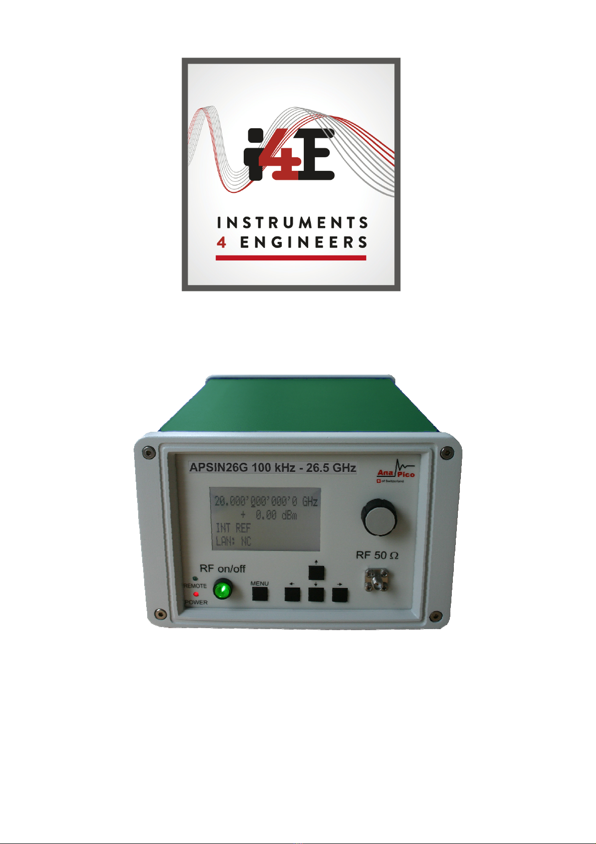
1.4
F
RONT
P
ANEL
O
VERVIEW
(APSIN
MODELS ONLY
)................................................................................................
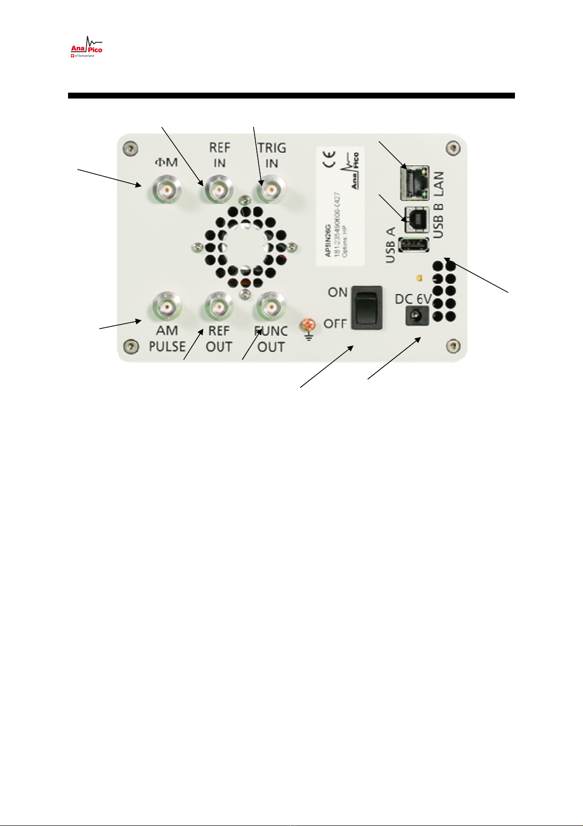
1.5
R
EAR
P
ANEL
C
ONNECTIONS
............................................................................................................................. 8
2
GETTING STARTED ................................................................................................................................. 10
2.1
S
YSTEM
R
EQUIREMENTS
................................................................................................................................ 10
2.2
U
NPACKING THE
I
NSTRUMENT
........................................................................................................................ 10
2.3
I
NITIAL
I
NSPECTION
...................................................................................................................................... 10
2.4
S
TARTING THE
I
NSTRUMENT
........................................................................................................................... 10
2.4.1
Applying Power ............................................................................................................................. 10
2.4.2
Connecting to LAN ......................................................................................................................... 11
2.4.3
Direct connectivity to host via Ethernet cable no router) ............................................................. 11
2.4.4
Connecting though USBTMC ......................................................................................................... 11
2.4.5
Installing the APSIN Remote Client ................................................................................................ 11
2.4.6
Troubleshooting the LAN Interconnection ..................................................................................... 12
2.4.7
Shutting Down the APSIN .............................................................................................................. 12
3
USING THE GRAPHICAL USER INTERFACE (GUI) ..................................................................................... 13
3.1
S
TART THE
APSIN
GUI ................................................................................................................................. 13
3.2
T
HE
COLTROL
T
AB
..................................................................................................................................... 13
3.2.1
Simultaneously controlling Multiple Signal Generators from one PC ............................................ 14
3.2.2
Store and Load Instrument States ................................................................................................. 15
3.2.3
Setting Network Configuration ...................................................................................................... 15
3.2.4
Setting the GPIB Address ............................................................................................................... 16
3.3
P
ERFORM
F
IRMWARE
U
PGRADE
..................................................................................................................... 16
3.4
U
SING
T
OOLBARS
........................................................................................................................................ 16
3.5
B
ASIC
CW
O
PERATION
(CW
TAB
) ................................................................................................................... 1
3.6
S
WEEPS
..................................................................................................................................................... 1
3.6.1
Frequency Sweep ........................................................................................................................... 18
3.6.2
Power Sweep ................................................................................................................................. 19
3.6.3
List Sweeps .................................................................................................................................... 19
3.
M
ODULATION
C
ONTROL
............................................................................................................................... 24
3.7.1
Pulse Modulation........................................................................................................................... 24
3.7.2
Pulse Train Modulation ................................................................................................................. 25
3.7.3
Amplitude Modulation .................................................................................................................. 26
3.7.4
Angle Modulation .......................................................................................................................... 26
3.7.5
Chirps ............................................................................................................................................. 27
3.8
R
EFERENCE
I
N AND
O
UT
................................................................................................................................ 28
3.8.1
Bypass internal 100 MHz reference ............................................................................................... 28
3.8.2
Output Internal Reference ............................................................................................................. 29
3.9
U
SING THE
T
RIGGER OPTIONS
(TRIGGER
TAB
) ................................................................................................. 29
3.10
LF
OUT
C
ONTROL
.................................................................................................................................. 30
3.11
C
OMBINED
M
ODULATION
........................................................................................................................ 32
4
LOCAL OPERATION VIA FRONT PANEL ................................................................................................... 33
4.1
D
ISPLAYED
P
ARAMETER
F
ORMATS
.................................................................................................................. 34
4.2
CW
D
ISPLAY
............................................................................................................................................... 34

Anapico AG Europastr. 9 CH-8152 Glattbrugg Switzerland Tel: +41 44 515 5501 www..anapico.com
4
4.2.1
Main Menu Display ....................................................................................................................... 34
4.2.2
Frequency Sweep Submenu ........................................................................................................... 35
4.2.3
Power Sweep Submenu ................................................................................................................. 36
4.2.4
List Sweep Submenu ...................................................................................................................... 38
4.3
M
ODULATION
S
UBMENU
.............................................................................................................................. 39
4.3.1
Pulse Modulation Submenu ........................................................................................................... 39
4.3.2
Amplitude Modulation Submenu .................................................................................................. 40
4.3.3
Frequency Modulation Submenu................................................................................................... 40
4.3.4
Phase Modulation Submenu ......................................................................................................... 41
4.4
R
EFERENCE
S
UBMENU
.................................................................................................................................. 42
4.5
T
RIGGER
S
UBMENU
...................................................................................................................................... 42
4.6
LF
OUTPUT
S
UBMENU
................................................................................................................................ 43
4.
LAN
C
ONFIGURATION
S
UBMENU
.................................................................................................................... 43
4.8
D
ISPLAY
S
ETTINGS
S
UBMENU
......................................................................................................................... 44
4.9
S
ETTINGS
S
UBMENU
..................................................................................................................................... 45
4.9.1
Save Settings Submenu ................................................................................................................. 45
4.9.2
Load Settings Submenu ................................................................................................................. 45
4.9.3
Load Defaults Submenu ................................................................................................................. 46
4.10
H
ELP
S
UBMENU
...................................................................................................................................... 46
5
REMOTE PROGRAMMING THE APSIN .................................................................................................... 48
6
BATTER OPERATION (B3 OPTION) ....................................................................................................... 49
7
EXTENDED POWER RANGE (PE3 OPTIONS) ............................................................................................ 52
8
MAINTENANCE AND WARRANT INFORMATION .................................................................................. 53
8.1
A
DJUSTMENTS AND
C
ALIBRATION
................................................................................................................... 53
8.2
R
EPAIR
...................................................................................................................................................... 53
8.3
S
AFETY
...................................................................................................................................................... 53
8.4
W
ARRANTY
I
NFORMATION
............................................................................................................................ 53
8.5
E
QUIPMENT
R
ETURNS
.................................................................................................................................. 54

Anapico AG Europastr. 9 CH-8152 Glattbrugg Switzerland Tel: +41 44 515 5501 www..anapico.com
5
1 Introduction
This instruction manual is valid for Anapico model series APSIN, APGEN, and APSYN. Chapter 2
gives you guidance for a quick and easy setup of your new instrument. Chapter 3 describes the
remote operation via Anapico graphical user interface (GUI). Chapter 4 describes control via front
panel and applies only to APSIN models.
1.1
What do you get?
Your signal generator kit contains the following items:
•Mainframe
•Universal power adaptor (AC 100 – 240V) with corresponding CH, UK, US, EU plugs
•Ethernet Cable
•Manuals & software CD
It is strongly recommended to use the original power adaptor (as supplied in this package) to
guarantee save and reliable operation of your instrument.
1.2 General Features and Functions (Model overview)
Anapico RF & Microwave Signal Generator model overview
Models
Range
Power range
Options
Display
APSIN
2
010
9 kHz – 2 GHz -30 - +15 dBm
B3, PE3, GPIB, RM Y
APSIN4010
9 kHz – 4 GHz -30 - +15 dBm
B3, PE3, GPIB, RM Y
APSIN6010
9 kHz – 6.1 GHz -30 - +15 dBm
B3, PE3, GPIB, RM, AVIO
Y
APSIN12G
100 kHz – 12 GHz -20 - +15 dBm
B3, PE3, GPIB, RM Y
APSIN20G
100 kHz – 20.4 GHz -20 - +15 dBm
B3, PE3, GPIB, RM Y
APSIN26G
100 kHz – 26.5 GHz -15 - +25 dBm
B3, PE3, GPIB, RM Y
APGEN3000
9 kHz – 3 GHz -65 - +13 dBm
- N (opt)
APSYN420
0.65 GHz – 20.4 GHz
+15 dBm - N
General features include
•Extendable power range (option PE3)
•Modulation capabilities for FM, PM, AM and PULM modulation (model dependant)
•Fast frequency, power and list sweeps
•Light weight, optional internal rechargeable batteries (option B3)
•3- inch status LCD (APSIN models only)

Anapico AG Europastr. 9 CH-8152 Glattbrugg Switzerland Tel: +41 44 515 5501 www..anapico.com
6
•Long-term support: Software upgrades (firmware, API, GUI) are available to download from
www.anapico.com. You can also call our technical specialists for support. You can continue to
use both of these services free of charge for the lifetime of the product.
•Universal LAN VXI-11 and USB 2.0 device and host interface
•18-24 months calibration cycle
1.3 Options
B3: internal rechargeable battery
FS: fast switching
PE3: mechanical step attenuator for extended power range
APSIN4010, APSIN6010
90 dB
APSIN20G, APSIN26G
7
5
dB
GPIB: GPIB interface added
AVIO: specific avionics modulation capabilities added
1URM: 19’’ 1HE enclosure

Anapico AG Europastr. 9 CH-8152 Glattbrugg Switzerland Tel: +41 44 515 5501 www..anapico.com
7
1.4 Front Panel Overview (APSIN models only)
The front panel contains a status display, RF output female N-type connector (APSIN4010,
APSIN6010) or a female SMA connector (APSIN12G, APSIN20G, APSIN26G), and a RF on/off key
(
Figure 1-a
). The LCD screen shows information on the current function. Information includes status
indicators, frequency and amplitude settings, current connectivity status, and error messages. Five
control buttons allow easy menu control.
Figure 1-a APSIN Front Panel View (Model APSIN20G)
RF On/Off button The ON/OFF key toggles between RF output on and RF output off. The green light
(*) is indicating whether the RF output is enabled (light on) or disabled (light off).
RF 50 Ωconnector This female N- type respectively SMA connector provides the output for generator
signals. The impedance is 50 ohm. The reverse power damage level is +30 dBm maximum. The
maximum allowed DC level is +/- 10 V. Please check the data sheets for more details.
Main LCD display The main display shows the following information:
1
st
line: RF frequency in Hz
2
nd
line: RF amplitude in dBm
3
rd
line: Frequency reference status (internal, external, lock status)
4
th
line: Remote control status

Anapico AG Europastr. 9 CH-8152 Glattbrugg Switzerland Tel: +41 44 515 5501 www..anapico.com
8
1.5 Rear Panel Connections
Figure 2 APSIN Rear Panel View
1 RJ-45 host connector Used for connecting with a controller such as PC or Laptop.
2 USB Device Used for connecting with a controller (PC, laptop).Communication via USB-TMC
protocol.
3 USB Host Used for connecting USB devices such as Memory sticks or USB-TMC power meters.
Check with factory for list of supported devices.
4 Phase MOD IN connector This BNC input connector accepts 0 to 2 V (peak) signal for frequency
and phase modulation. The damage level is 4 Vrms.
5 REF IN connector Female BNC connector accepts a TTL or -5 to +15 dBm sine signal from an
external reference oscillator that is within ±1 ppm of the programmed reference frequency. The
nominal input impedance is 50 ohm.
6 TRIG IN connector Female BNC connector accepts TTL signal from an external trigger source. The
input impedance is 1Mohm.
7 AM / PULSE MOD IN connector This BNC input connector accepts TTL signal for pulse modulation
respectively analogue voltage for AM. The damage level is 5 Vrms.
8 REF OUT connector Female BNC connector is for an output of the internal 10 or 100 MHz
reference frequency which has a nominal output level greater than 0 dBm and an output impedance of
50 ohm.
9 FUNCT OUT connector Female BNC connector is used as a multiple purpose output. It can be
programmed as trigger output, as video output during pulse modulation and as output for the low
frequency function generator.
4
10 11
1
5 6
7
8 9
2
3

Anapico AG Europastr. 9 CH-8152 Glattbrugg Switzerland Tel: +41 44 515 5501 www..anapico.com
9
10 Power switch The power switch disconnects the signal generator from the DC input completely
including the internal high-stability reference. After switching on this switch the signal generator enters
into standby with the OCXO warming up and RF out switched off. The red power LED on the front
panel is turned on.
11 DC IN power receptacle The power receptacle accepts two-pin plug from the external 6 V DC
power adapter.

Anapico AG Europastr. 9 CH-8152 Glattbrugg Switzerland Tel: +41 44 515 5501 www..anapico.com
10
2 Getting Started
2.1 System Requirements
The Anapico graphical user interface requires at least the minimum system requirements to run one of
the supported operating systems.
Operating system Windows™ 2000 SP4, XP SP2, Vista, 7, 8
Remote 10/100/1000M Ethernet or USB 2.0 Port
2.2 Unpacking the Instrument
Remove the instrument materials from the shipping containers. Save the containers for future use.
The standard product package includes:
1 Synthesized Signal Generator
1 Ethernet Cable
1 Universal DC power adapter
1 Software & Manual CD
2.3 Initial Inspection
Inspect the shipping container for damage. If container is damaged, retain it until contents of the
shipment have been verified against the packing list and instruments have been inspected for
mechanical and electrical operation.
2.4 Starting the Instrument
This section describes installation instructions and verification tests.
2.4.1 Applying Power
Place the instrument on the intended workbench and connect the appropriate DC power supply to the
receptacle on the rear of the unit. Make sure you use the included DC power supply. The instruments
typically require 6 V DC at 3A peak. Using other supplies may lead to malfunction and damage of
the Instrument.
Press the line on/off switch on the rear panel. If available, the front panel display will illuminate. The
instrument will initialize and momentarily display the model number, firmware revision and product
serial number. The display will then switch to the factory default display setting, showing preset
frequency (100 MHz) and power (0.0 dBm), phase lock status (of internal reference) and instrument
connectivity status (Ethernet IP or USB identifier).
Note, the instrument booting process may take up to 60 seconds (depending on configuration) to
complete.

Anapico AG Europastr. 9 CH-8152 Glattbrugg Switzerland Tel: +41 44 515 5501 www..anapico.com
11
2.4.2 Connecting to LAN
Connect the instrument to your local area network (LAN) using the Ethernet cable. By default the
instrument is configured to accept its dynamic IP number from the DHCP server of your network. If it is
configured properly, your network router will assign a dynamic IP number to the instrument which will
be automatically displayed on the screen. Your instrument is now ready to receive remote commands.
2.4.3 Direct connectivity to host via Ethernet cable (no router)
You can connect to the instrument to your computer with the Ethernet cable without using a local area
network with DHCP server. To work properly, the network controller (NIC) of your computer must be
set to a fixed IP beginning with 169.254.xxx.xxx (excluding 169.254.1.0 and 169.254.254.255) and
network mask 255.255.0.0 to match the fallback IP that the APPH will assign itself after network
timeout. The APPH will automatically choose an IP address according to ZEROCONF standard.
Therefore, the exact fallback address can’t be predicted.
Connection from a NIC that is configured to use DHCP is also possible. After a preset timeout, the NIC
will assume that no DHCP is available and self-assign a fallback IP that will fall into the range
169.254.xxx.xxx.
Alternatively, you may assign the instrument a fixed IP. Please refer to a later section of this manual to
learn how to do this.
2.4.4 Connecting though USBTMC
Connect the (powered on) instrument to the computer using the USB cable. If properly connected, the
computer host should automatically recognize your instrument as a USBTMC device.
Note if you want to work with the Anapico GUI, it must be installed with USB support selected. Then
the GUI will detect all attached devices automatically. Open the GUI and follow the instructions given
in Chapter 4.
Alternatively, a VISA runtime environment (NI or Agilent or comparable) must be installed.
Use VISA Write to send the *IDN? Query and use VISA Read to get the response. The USBTMC
protocol supports service request, triggers and other GPIB specific operations.
2.4.5 Installing the APSIN Remote Client
Anapico’s graphical user interface provides an intuitive control of the instruments. It runs under
Windows™ operating system with minimum requirements. The DLL is embedded in the GUI
application and requires the Microsoft® .NET™ framework to be installed. To install the GUI on the
computer, insert the Anapico Software and Manual CD into the CD/DVD drive. If the setup doesn’t
start automatically double click on the setup.exe to run the auto-installer.
The self-extracting setup provides easy installation and de-installation of the software. The setup
program guides you in a few steps though the installation process. In case the NET framework is not

Anapico AG Europastr. 9 CH-8152 Glattbrugg Switzerland Tel: +41 44 515 5501 www..anapico.com
12
installed on your current Windows™ operating system, the setup procedure will assist you
automatically to install the required version. For this you will need an active internet connection.
2.4.6 Troubleshooting the LAN Interconnection
Software does not install properly
•Make sure your installation CD is not damaged.
•When Microsoft .NET Framework is not installed make sure that your computer is connected
to the internet during installation of the Anapico Software. If no internet connection is
available, install the .NET™ Framework that is available on the installation CD.
Software cannot detect any instrument
•Make sure you have connected both computer and instrument to a common network.
•If a direct connection is used you may require to reset your computer Ethernet controller
(depending on the configuration). Note that in that case detection of the instrument can take
a considerable amount of time if your computer is configured to work with an external DHCP
server. In some cases the detection may even fail completely. Configure your computer
network controller to an appropriate fixed IP instead.
•Make sure that your software firewall enables the GUI to setup a TCP/IP connection via the
LAN. Under Windows XP you can do that like this:
Open Control Panel under Settings in your Start menu. Then go to Windows Firewall. Click on
Exceptions and then add Program. If the GUI is in this list, choose it and click OK otherwise
you have to browse for the path to GUI installation directory. Finally close all open dialogs with
OK. Now your Windows™ Firewall will not block requests from the GUI.
2.4.7 Shutting Down the APSIN
Press the line on/off switch on the rear panel to off.

Anapico AG Europastr. 9 CH-8152 Glattbrugg Switzerland Tel: +41 44 515 5501 www..anapico.com
13
3 Using the Graphical User Interface (GUI)
Anapico’s graphical user interface provides an intuitive control of the signal generator. It runs under
any Windows™ operating system. Make sure the software is installed correctly and the computer’s
firewall is configured properly. The GUI’s dynamic link library (DLL) uses the Microsoft .NET
framework.
3.1 Start the APSIN GUI
After successful installation of the software double-click the software shortcut that has been created on
your desktop.
After start the GUI will automatically detect existing Anapico instruments that are connected to the
computer (network) via local area network, USB, or GPIB. In the CONTROL tab (see
Figure 3-a
)
the detected instruments are listed. Clicking on one of the devices will instantly establish connection.
Clicking on an alternate device will disconnect the old device and reconnect to the new device. Scan
Instruments button will enable automated scanning for new instruments. Disconnect/Connect
button will establish and terminate connection.
3.2 The COLTROL Tab
The CONTROL tab (Figure 3-a) completes the following function
- Scan and establish connection to instrument
- Configure remote interface (LAN, USB, GPIB)
- Save, load and manage instrument memory states

Anapico AG Europastr. 9 CH-8152 Glattbrugg Switzerland Tel: +41 44 515 5501 www..anapico.com
14
Figure 3-a CONTROL Tab
3.2.1 Simultaneously controlling Multiple Signal Generators from one PC
You can easily control multiple Anapico instruments from a single computer but you need to start a
separate GUI for every instrument as only one instrument is controlled by the GUI at once.

Anapico AG Europastr. 9 CH-8152 Glattbrugg Switzerland Tel: +41 44 515 5501 www..anapico.com
15
3.2.2 Store and Load Instrument States
Multiple different memory states are available to store instant instrument settings. By clicking on the
Device Settings Memory button the currently saved memory settings are displayed and can be
loaded or overwritten as shown in
Figure 3-b
. To modify or enter a state, click on the appropriate line and select if the current
instrument settings shall be stored in or loaded from the selected memory state.
NOTE: Memory 0 is used as default state when the instrument is powered up.
The memory states can also be accessed via the front panel menu.
Figure 3-b Memory Settings Submenu
3.2.3 Setting Network Configuration
If your network does not have a DHCP server or a static IP address is preferred you can set an IP
address, network mask and default route. The address and mask settings are required. The default
route is not strictly necessary but enables network communication between the test set and devices on
a subnet other than that to which it is immediately attached. The network features can be used on the
local area network even if no default route (specified as 0.0.0.0) is configured.
The Network Configuration button allows configuring the LAN settings as shown in
Figure 3-c
.
Using a DHCP (dynamic host configuration protocol) server can be enabled or a static IP can be
entered by user. The device name can be modified as desired. The unit serial number and firmware
revision are displayed on the bottom.

Anapico AG Europastr. 9 CH-8152 Glattbrugg Switzerland Tel: +41 44 515 5501 www..anapico.com
16
Figure 3-c Network Configuration Submenu
3.2.4 Setting the GPIB Address
If the instrument has the GPIB option installed, the GPIB address can be changed in the GPIB
submenu in the control tab. Valid GPIB address is 1 to 30.
To verify GPIB functionality, use the VISA Assistant available with the Agilent IO Library or the Getting
Started Wizard available with the National Instrument IO Library. These utility programs enable you to
communicate with the signal generator and verify its operation over GPIB. For information and
instructions on running these programs refer to the Help menu available in each utility.
3.3 Perform Firmware Upgrade
A firmware upgrade of the instrument can be done directly via the GUI. First make sure you are
connected to the right instrument and have the correct firmware binary file (.rar) ready. Then apply
Controller Update Firmware and select the appropriate binary file that you have received from
Anapico or downloaded from the Anapico website. The update will take a few seconds and after
completion your instrument will reboot. Reconnect to the instruments after booting is completed and
continue with the updated firmware. NOTE: Do not disconnect and power off device during
firmware update is in process.
3.4 Using Toolbars
In the existing GUI Version there are two Toolbars available.
The standard toolbar looks like: with the following symbol functionality:
Close the Application
Connect / Disconnect

Anapico AG Europastr. 9 CH-8152 Glattbrugg Switzerland Tel: +41 44 515 5501 www..anapico.com
17
Save to Memory
Network Configuration
Reset System
Restart Controller
3.5 Basic CW Operation (CW tab)
Anapico signal generators are laboratory instruments designed to generate a synthesized CW signal
with good spectral purity and fixed or variable amplitude. To set a desired frequency, relative phase
and amplitude, click to the CW tab (
Figure 3-d
). The desired frequency, phase and power can be
set by clicking on the up and down arrows above and below each digit. The frequency is settable in
steps of 0.001 Hz, the phase is settable in steps of 0.1 degrees and the power in steps of 0.01 dB.
The RF ON/OFF button turns the RF power on and off. The green LED in the RF ON button indicates
that the RF output is enabled. The MOD ON/OFF button allows instant enabling (disabling) of a
previously enabled
modulation.
Figure 3-d CW Tab
3.6 Sweeps
Besides the basic CW operation, the instrument supports several sweeping modes. Sweep
parameters can be set in the SWEEP tab (
Figure 3-e
). Select frequency, power or list sweep by
clicking on the FREQ. SWEEP, POWER SWEEP or LIST SWEEP tab respectively.

Anapico AG Europastr. 9 CH-8152 Glattbrugg Switzerland Tel: +41 44 515 5501 www..anapico.com
18
3.6.1 Frequency Sweep
To start a frequency sweep,
a) enter start and stop frequency in Hz unit
b) enter the number of points (or points per decade)
c) enter the dwell time in milliseconds (min. dwell time is 50 microseconds)
d) enter the off time in microseconds
e) select the sweep mode as linear or log; additionally click “random” if random sequence is
desired
f) select the repetition mode: enter number of repetitions or choose “infinite”
g) select the ALC mode: on hold or off. Generally ALC on is used. If very short dwell times (1-2
ms) are needed, the ALC can be set to “hold”. In this way the ALC loop is disabled during the
sweep. The ALC voltages are calibrated before the sweep to maintain high level accuracy
during the sweep
h) press the on/off button
The time resolution is 200 ns. Note that the sum of the dwell time and the off time must be greater or
equal to 1.0 ms. The dwell time must be at least 50 µs. The off time can be also be 0 (no off time).
When “auto” is selected, the off time is automatically adjusted such that during switching transients the
output is disabled and the sum of dwell and off time are at least 1.0 ms.
Under “repetition mode” you can select how many times the sweep should be executed by entering 1
to N times or select infinite. Selecting “Rand” will sweep the frequencies in a random manner until
terminated by user. In all cases the frequency returns to the CW frequency as soon as the sweep is
terminated.
Start and stop the sweep by pressing the ON/OFF button.
The switching transient between frequency steps depends on the step size and if internal bands of the
synthesizer are crossed. Typical switching transients are <10 µs for a <100 MHz step (no band
crossing) and <50 µs for arbitrary steps at output frequencies.
3.6.1.1 Frequency Linear Sweep
This mode sweeps linearly from start to stop frequency in constant steps. Frequency step size is
(f_stop-f_start)/number_of_points.
If start<stop then negative frequency steps are performed.
3.6.1.2 Frequency Log Sweep
This mode sweeps logarithmically from start to stop frequency in a given number of points per decade.
3.6.1.3 Frequency Random Sweep
The output frequency is selected randomly between start and stop frequency. The number of different
output frequencies is determined by the number of points selected by the user.

Anapico AG Europastr. 9 CH-8152 Glattbrugg Switzerland Tel: +41 44 515 5501 www..anapico.com
19
3.6.2 Power Sweep
To run a power sweep, enter start and stop power in dBm unit, the number of steps, dwell and off time
in milliseconds. When “auto” is selected, the off time is automatically adjusted such that during
switching transients the output is disabled and the sum of dwell and off time are at least 400 µs.
Select if the sweep should run a predefined number of times (enter desired number) or infinite times
(selecting infinite). Select ALC settings. Start and stop the sweep by pressing ON/OFF button.
Figure 3-e FREQUENCY SWEEP Tab
3.6.3 List Sweeps
List sweeps allow to set frequency, output power, dwell time and off time for each entry individually. To
start a list sweep, the following steps are required:
a) select sweep parameter
b) select indexing
c) upload list file from computer (CSV-file) or load sweep from instrument flash memory or edit
new list
d) select number of repetition
e) select ALC mode: on, hold or off. Generally ALC on is used. If very short dwell times (< 2 ms)
are needed, the ALC can be set to “hold”. This way the ALC loop is disabled during the

Anapico AG Europastr. 9 CH-8152 Glattbrugg Switzerland Tel: +41 44 515 5501 www..anapico.com
20
sweep. The ALC voltages are calibrated before the sweep to maintain high level accuracy
during the sweep
f) start sweep with on/off button
Figure 3-f POWER SWEEP Tab
Select parameter to sweep: frequency, power or both. If only one parameter is selected to sweep, the
second parameter is set to the first value (line 1 of the CSV file) for the duration of the sweep.
Choose the direction of the sweep: to go up, down or be random. If you select random indexing, the
index is randomly chosen for N times where N is the number of list points.
3.6.3.1 Sweep File Format
The input file must be a 4 column CSV file with the following syntax on each line:
frequency [in Hz] ; power [in dBm] ; dwell time [in µs] ; off time [in µs]
Note the four entries in each line must be separated by a semicolon.
Figure 3-h
shows a valid list file with four points displayed in Microsoft Excel. Each line describes
one list point. The first line must contain all for entries, in any other line entries may be omitted. Lists
may contain up to 10’000 lines.
Other manuals for APSIN Series
1
This manual suits for next models
10
Table of contents