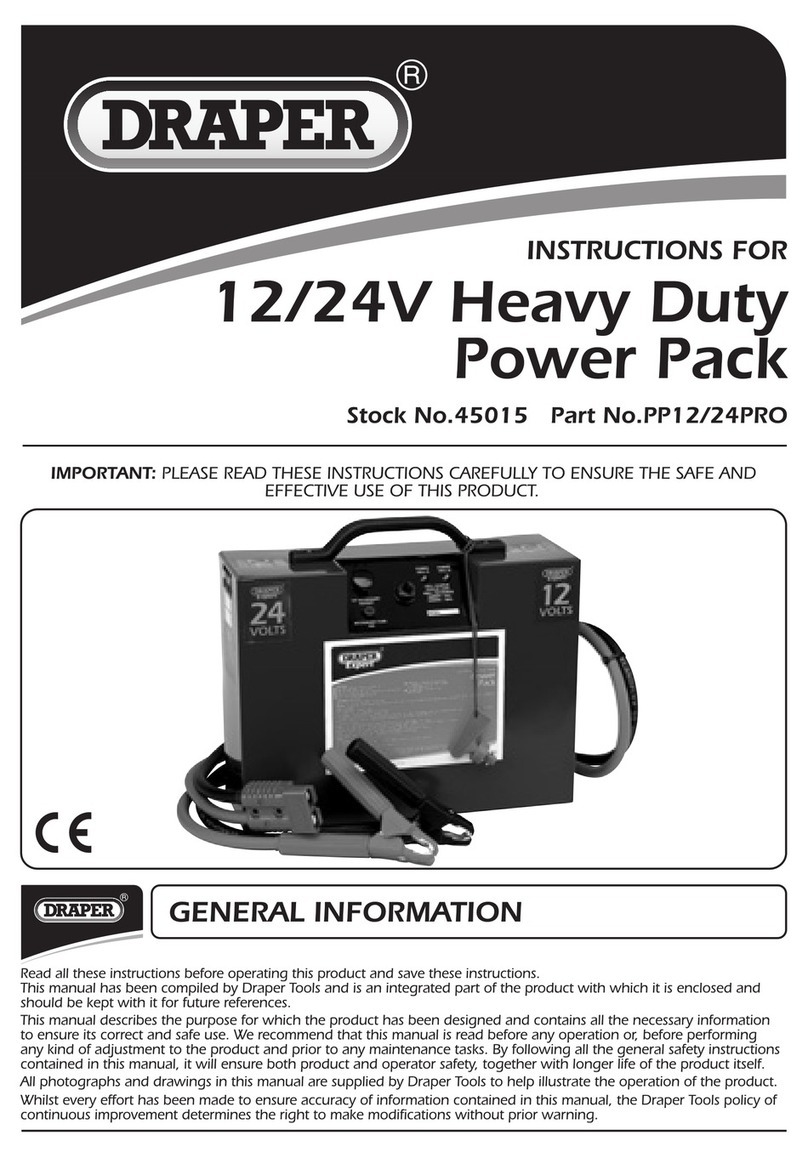
Anchor Systems 46913 Manual

www.anchorsystems.co.uk
20-30L Hydraulic
Power Pack
OPERATING INSTRUCTIONS
AND TECHNICAL INFORMATION

Power Pack Contents
These instructions give safety and operations information regarding the use of a
trailer mounted Hydraulic Power Pack supplied by Anchor Systems (International)
Ltd. They contain the relevant information for products:
To ensure optimum results when operating this equipment it is very important to read this manual carefully, the
information will prepare you to do a better, safer job.
Before operating the machine you should familiarise yourself with the instructions in this manual. Incorrect use
can lead to damage which is not covered by the Warranty Conditions. This may create a dangerous situation or
lead to unsatisfactory results.
These operating instructions MUST always be made available to the person or persons operating this equipment.
To assist in the ordering of spares, or other communications with our company, the serial number of the relevant
equipment supplied, has been recorded below for your information.
Model No:-
Serial No:-
Date of Delivery:-
PRODUCT CODE DESCRIPTION PRESSURE FLOW
46913 Midipac Assembly 140 Bar 20-30 Lpm
Information.........................................................................4
Safety Instructions….......................................................................4
Daily Check Items...........................................................................5
Hydraulic Power Pack.....................................................................6
Power Pack Operation…..............................................................7
Pre-Operation Check List…...............................................................7
Operation…..........................................................................7
Oil Flow Control…..........................................................................10
General Precautions….........................................................11
Safety Rules…..........................................................................11
Safety Features….....................................................................11
Personal Protection..................................................................11
Unauthorised Modication........................................................11
Operating Safety….........................................................................12
Turning Off….................................................................................12
Routine Maintenance.......................................................….......13
Troubleshooting................................................................16
Spare Parts…...........................................................................17
End of Life..............................................................................26
Risk Assessment – Operation of Power Pack 20-30L.......................27
Section 1: Assessment Information...............................................27
Section 2: Likelihood / Severity of Injury.......................................27
Section 3: Control Measures.........................................................28
Further Action Required.................................................................28
Have any questions?
01342 719 362
www.anchorsystems.co.uk
2 3
Information
Your Hydraulic Power Pack has been individually built with great emphasis on quality,
strength and simplicity of design and with routine care will give many years of trouble
free operation.
For further details on location and service parts see Routine Maintenance.
The following instructions have been written to cover the machine. Care should be taken to ensure that
you are referring to the correct section of your machine before carrying out any adjustments, or when
ordering spare parts.
Like all mechanical products, regular cleaning, lubrication and maintenance will ensure a longer trouble free
life. These instructions make no attempt to go beyond routine maintenance, and it is strongly advised that you
contact your dealer should any major repairs become necessary.
Use only genuine service parts; non genuine parts may not meet standards required for safe and satisfactory
operation.
1. Read and understand this operator’s manual prior to operating the machine and keep it in a
convenient place for future reference.
2. Keep untrained personnel away from the machine whilst it is in operation.
3. Do not operate machine with any panels removed.
4. Beware, pressured hydraulic oil can be very dangerous and can penetrate the skin - TAKE THE
UTMOST CARE.
5. Keep hands, feet and loose clothing away from moving parts.
6. Always switch off the machine before making any adjustments or when carrying out lubrica-
tion and servicing.
7. Keep all nuts, bolts and fasteners tightened.
8. Check machine regularly for damaged or worn parts.
1. Check the hydraulic hoses are connected to the Hydraulic Power Pack
and the hoses are not perished or leaking.
2. Check oil cooler fan for obstruction.
3. Check engine oil level. (0.82-0.95L)
4. Check fuel level.
5. Check hydraulic oil level.
Have any questions?
01342 719 362
www.anchorsystems.co.uk
4 5
Daily Check Items
Observe all safety information in the manual and on decals tted
to the machine and power unit.
SAFETY INSTRUCTIONS:
NOTE: PLEASE TAKE NOTICE OF ALL WARNING
DECALS RELATING TO YOUR MACHINE
The power pack uses HLP 32 Grade Hydraulic Mineral Oil.

www.anchorsystems.co.uk
Power Pack OperationHydraulic Power Pack
The safe operation of this equipment is the responsibility of the operator.
1. Keep bystanders away from the machine.
2. Ensure you are aware of the environment you are working in; including overhead cable,
underground installations etc.
3. Observe all safety instructions and warnings.
PRE-OPERATION CHECK LIST
1. Ensure the hydraulic hoses are connected to both the powerpack and attachment.
2. Turn the valve block lever to the OFF position when starting and stopping the engine.
3. Turn the switch to the ON position to allow the engine to start.
4. Ensure the auto throttle is NOT locked in HIGH.
5. Pull the pull-cord to start the engine.
6. Turn the ow control valve to ON.
7. Check the oil level in the reservoir (if using new and empty hoses) and ll up if needed.
OPERATION
Figure 1 – Operation 1
Have any questions?
01342 719 362
6 7

Figure 2 – Auto-Throttle and Pull Cord
Figure 3 - Flow Control Valve Block (OFF)
Figure 4 - Engine On-Off Switch
Figure 5 - Oil Level Gauge
Have any questions?
01342 719 362
www.anchorsystems.co.uk
Power Pack Operation
8 9
Power Pack Operation

Figure 6 –
Flow Selector Handle
Figure 7 -
Throttle Lock
• Only trained and qualied personnel or personnel authorised by the company (or superior) can
operate and maintain the machine.
• Follow all safety rules, prohibitions, precautions, procedures, and instructions when operating or
performing maintenance on the machine and pay careful attention to safety.
• Operating the machine when you are not in good physical condition reduces the power of judgment
needed to avoid danger and leads to accidents.
• People in the following conditions should not operate the machine.
o People who cannot operate normally because they are ill or suffering from the effects of
medication.
o People who have been drinking
o Pregnant women
SAFETY RULES
• Be sure that all guards and covers are in their proper position. Have guards and covers repaired if
damaged.
• Improper use of safety features could result in serious bodily injury or death.
SAFETY FEATURES
• Avoid loose clothing, towels, jewellery, and loose long hair. They can catch on controls or in moving
parts and cause injury or death.
• Also, do not wear oily clothes; they can easily catch re.
• Wear a hard hat, safety glasses, non-slip safety shoes and gloves when operating or maintaining
the machine.
PERSONAL PROTECTION
• Any modications made without authorisation from Anchor Systems (International) Ltd can ad-
versely affect the performance of the machine and they may also create hazards.
• Before making a modication, consult Anchor Systems (International) Ltd. Anchor Systems (Inter-
national) Ltd will not be responsible for any injury or damage caused by any unauthorised modi-
cation.
UNAUTHORISED MODIFICATION
Have any questions?
01342 719 362
www.anchorsystems.co.uk
10 11
General Precautions
The Midipac has an auto-throttle function which will increase the engine output as demand
for oil pressure increases. The Midipac can operate in two modes: 20 Litres a minute; and
30 Litres a minute. To switch between 20 and 30Lpm, operate the ow selector handle on
the oil reservoir lid.
Oil Flow Control
When in 30 Lpm mode the engine will automatically rev up to prevent stalling as the pressure requirements
increase.
The auto-throttle can also be locked in HIGH mode. This is done by pulling the throttle contact plate forward and
placing the ‘R clip’ into the nearest hole to the throttle arm.
WARNING: Failure to follow these general safety precautions
may lead to a serious accident.
The safe operation of this rig is the responsibility of the operator, who should
be familiar with the principles of pile installation, the power unit, and all safety
practices before starting operations.

Operating Safety
• Always operate the machine when on level and stable ground.
• All outriggers should be deployed to ensure machine stability.
• Ensure all operators are wearing the required PPE.
• All operators should be familiarly with the machine controls and operating procedure.
• All workforce should be clear of the machine when in operation.
• Do not block the radiator grills or exhaust pipe.
• Do not put any hands or foreign objects into the machine.
• Keep feet and hands clear when operating the machine.
• Turn the ow control valve to OFF
• If the auto throttle is locked in HIGH, unlock it
• Turn the engine cut off switch OFF
Figure 8 - Oil Suction Filter
Have any questions?
01342 719 362
www.anchorsystems.co.uk
12 13
Routine Maintenance
Engine - refer to Vanguard 6.5 operator’s manual for service intervals.
Oil Dipstick - located at the right side of the engine
Hydraulic return lter- Located on the left of the power pack.
Hydraulic Oil Reservoir - Oil suction ller is inside the oil reservoir. Oil level sight gauge is located
on the right side of the reservoir, oil level must be checked on a weekly basis. The power pack uses
HLP 32 Grade Hydraulic Mineral Oil.
For safe use, ensure all these points are followed:
TURNING OFF

Figure 9 -
Oil Filler Breather
Figure 10 -
Fuel Filler
Have any questions?
01342 719 362
www.anchorsystems.co.uk
14 15
Routine Maintenance Service Information
The service schedule of machine items is as follows:
SERVICE SCHEDULE
SERVICE ITEM
SERVICE INTERVAL
10 Hours
Daily
50 Hours
Weekly
500 Hours
6 Months
1000 Hours
Annually
ENGINE
Oil Level Check
Oil Leaks Check
Fuel Filter Change
Oil and Filter Change
All Hoses Check
Radiator Clean
Air Cleaner Inner Element Change
HYDRAULICS
Hydraulic Oil Check Change
Hydraulic Oil Suction Filter Change
Hydraulic Oil Return Filter
OTHER
Fuel Check
Bolts Check

CODE DESCRIPTION
46885 HYDRAULIC ASSEMBLY
NO. CODE DESCRIPTION QUANTITY
1 46886 Hose 1 1
2 46892 Hose 2 1
3 46893 Hose 3 1
4 46894 Hose 4 1
5 46897 Hose 5 1
6 49743 Hose 6 1
Have any questions?
01342 719 362
www.anchorsystems.co.uk
16 17
Troubleshooting
SYMPTOM POSSIBLE CAUSE ACTION
Won’t Start Engine cut off switch set to OFF Turn switch to ON
Hard to Start Fuel blockage Replace lter
Choke is open Close choke while starting
Valve block is in the ON position Turn the valve to the OFF position
Low fuel Fill up
Auto throttle locked to high
mode Enable auto throttle
Engine stalling Hydraulic load too high Check auto throttle position
Low fuel Check fuel level
Excessive Oil
Temperature Low oil Check dipstick and top up
Oil leaks Loose Fittings Tighten Up Fittings
Leaky Connections Reseal or check Conguration
Damaged hose Replace hose
Spare Parts - Hydraulics

CODE DESCRIPTION
49050 POWER PACK ASSEMBLY
NO. CODE DESCRIPTION QUANTITY
1 46835 Tank Mounting Plate 1
2 11885 Fan Blade 1
3 11886 Oil Cooler 1
4 46901 Fan Retainer 1
5 46861 Fan Adaptor 1
6 46888 Midipac Reservoir Assembly 1
7 46889 Midipac Engine Assembly 1
8 46890 Mani Valve Boss Assembly 1
9 46828 Cooler Guard Panel 1
10 11876 Element Filter 1
11 11875 Inline Filter 1
12 11871 Midipac Bonded Foot 2
13 11870 Midipac Wheel 2
14 48663 Midipac Axle 2
15 49252 Power Pack Handle WA 1
16 49747 Frame Beam 8 WA 1
17 48063 Fan Cowl WA 1
18 48482 Fan Spacer 1
19 49749 Tray WA 1
20 11871 Midipac Bonded Foot 2
21 49612 Switch Plate 1
22 12474 Switch 1
23 49815 Fan Cowl Mesh 1
Have any questions?
01342 719 362
www.anchorsystems.co.uk
18 19
Spare Parts - Power Pack Spare Parts - Power Pack

Have any questions?
01342 719 362
www.anchorsystems.co.uk
20 21
Spare Parts - Engine Spare Parts - Engine
CODE DESCRIPTION
46889 POWER PACK ENGINE ASSEMBLY
NO. CODE DESCRIPTION QUANTITY
1 11883 Bell Housing 1
2 11882 Flexible Coupling 1
3 11884 Pump 1
4 01097 Adaptor 1
5 2182 Seal 1
6 02977 Washer M8 (Form C) 4
7 08017 Bolt Cap M6 x 25 4
8 11893 Key 1
9 12481 Bolt Hex 5/16" UNF x 1" 2
10 46835 Tank Mounting Plate 1
11 12441 Engine 1
12 49600 Auto Throttle Assembly 1
13 02350 Washer M6 (Form C) 3
14 02515 Washer Spring M6 1
15 02475 Bolt Set M6 x 16 1
16 11046 Nut Full M6 1

CODE DESCRIPTION
46888 RESERVOIR ASSEMBLY
NO. CODE DESCRIPTION QUANTITY
1 11877 Oil Level Gauge 1
2 11890 Return Bush 1
3 46848 Midipac Suction Adaptor 1
4 01126 Elbow 012 SW MF BSP 1
5 rh447 Suction Strainer 1
6 11874 Breather Filler w/strainer 1
7 2276 Seal Bonded 010 1
8 01097 Adaptor 008 MM BSP 1
9 02350 Washer M6 (Form C) 6
10 01812 Seal Bonded 006 1
11 01677 Plug 006 1
12 02475 Bolt Set M6 x 16 6
13 04919 3/8" Lock Nut 1
14 48067 Oil Reservoir 1
15 02182 Seal Bonded 008 1
16 46836 Tank Lid 1
17 11894 Top Mounted Valve 1
18 09585 Bolt Hex M4 x 20 2
19 09266 Washer M4 (Form C) 2
Have any questions?
01342 719 362
www.anchorsystems.co.uk
22 23
Spare Parts - Reservoir Spare Parts - Reservoir

Have any questions?
01342 719 362
www.anchorsystems.co.uk
24 25
Spare Parts - Main Valve
CODE DESCRIPTION
46890 MAIN VALVE ASSEMBLY
NO. CODE DESCRIPTION QUANTITY
1 46867 Main Valve Assembly 1
2 01097 Adaptor 008 MM BSP 4
3 2182 Seal Bonded 008 6
4 09191 QR FF 1/2" F 1
5 09206 QR FF 1/2" M 1
Spare Parts - Auto Throttle
CODE DESCRIPTION
49600 AUTO THROTTLE ASSEMBLY
NO. CODE DESCRIPTION QUANTITY
1 48666 Throttle Ram Assembly 1
2 49532 Throttle Locking Rod 1
3 04275 Stauff Clamp Single M022 1
4 46839 P.O.B. Bracket 1
5 02798 Clip R M002 1
6 49601 Throttle Lock Tube WA 1
7 49531 Throttle Pushing Plate 1
8 02350 Washer M6 (Form C) 6
9 02513 Nut Nyloc M6 2
10 02347 Bolt Hex M6 x 60 2
11 12263 Nut Full M5 2

SECTION 1: ASSESSMENT INFORMATION
SECTION 2: LIKELIHOOD/SEVERITY OF INJURY
Have any questions?
01342 719 362
www.anchorsystems.co.uk
26 27
End Of Life
COMPONENT WHAT TO DO?
Metals All metals should be recycled with an appropriate scrap metal merchant,
preferable sorted into metal type.
Electronics All electrical components should be recycled at an appropriate facility ac-
cording to the WEEE Directive and Regulations 2013
Oils Oil waste is classed as Hazardous and therefore must be stored separately
and according to legal regulations (that differ dependent on country). It
must be disposed of be a suitable Waste Oil collection company.
Hydraulic Hoses Hydraulic hoses should be drained of oil, metal ends removed and then
recycled with a suitable specialist recycling company. Metal ends can be
sent to metal recycling centres.
Plastics All plastics should be sorted into recyclable and no recyclable and then
either sent to suitable recycling facilities or landll.
Risk Assessment –
Operation Of Power Pack 20- 30l
When the machine reaches the end of its useable lifetime it is important that the inde-
pendent elements of the machine are reused, recycled, or disposed of suitably.
ASSESSMENT DATE 17/03/2020
ACTIVITY / ITEM / AREA Operation of Power Pack 20-30L
PERSON AT RISK Installation Operative and others in the work area
TOTAL NUMBER OF PEOPLE AT RISK 1+
RESPONSIBLE PERSON Machine Operative, Installation Operative
ASSESSOR Sebastian Ulrik
SIGNIFICANT RISKS LIKELIHOOD SEVERITY RESIDUAL
1. Manual handling 2 2 4
2. Burns 2 1 2
3. Injury caused by rotation 1 2 2
LIKELIHOOD
SEVERITY
MINOR SERIOUS MAJOR FATALITY MULTIPLE
1 2 3 4 5
Rare 1 1 2 3 4 5
Unlikely 2 2 4 6 8 10
Moderate 3 3 6 9 12 15
Likely 4 4 8 12 16 20
Certain 5 5 10 15 20 25
Low Risk Moderate
Risk Signicant
Risk High Risk
Likelihood X Severity = Residual Risk

1. Appropriate PPE is worn including hard hat, safety glasses, gloves and high-visibility clothing
as a minimum. Ear protection may be required when operating or working in close proximity to
the power pack.
2. Machine Operatives will maintain a line of sight with the machine at all times.
3. Operators will ensure that all unauthorised persons are kept away from the work area, by
bounding off the area if practicable.
4. The gearbox will be operated in a controlled manner to avoid potentially hazardous practises.
5. Installation Operatives will familiarise themselves with the layout of the work area, will avoid
working in poor or incomplete excavations and report any hazardous ground conditions to the
Site Manager.
6. All operators to be trained in machine use and safety prior to operation.
7. All hand tools will be kept in good order and only used for their design purpose. Faulty/bro-
ken/worn items will be replaced.
8. Operators are to be in possession of, have read and understood the machine and operation
instruction manual.
9. Prestart check carried out and any faults reported immediately.
10. Keep away from the engine exhaust while or after engine has been running, for reasonable
amount of time.
FURTHER ACTION REQUIRED:
Have any questions?
01342 719 362
www.anchorsystems.co.uk
28 29
Section 3: Control Measures
NO FURTHER ACTION REQUIRED
Prepared By
Anchor Systems (International) Ltd
In Pictures

FOR TECHNICAL ADVICE OR
FURTHER INFORMATION PLEASE CONTACT:
ANCHOR SYSTEMS (INTERNATIONAL) LTD
Unit 44 - 46, Rowfant Business Centre,
Rowfant, West Sussex RH10 4NQ
Tel: +44 (0)1342 719 362
Web: www.anchorsystems.co.uk
VULC010418
QUALIFIED
UVDB
www.anchorsystems.co.uk
PP06082021
Table of contents