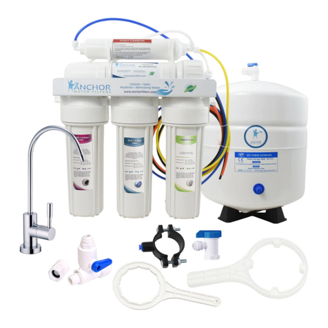
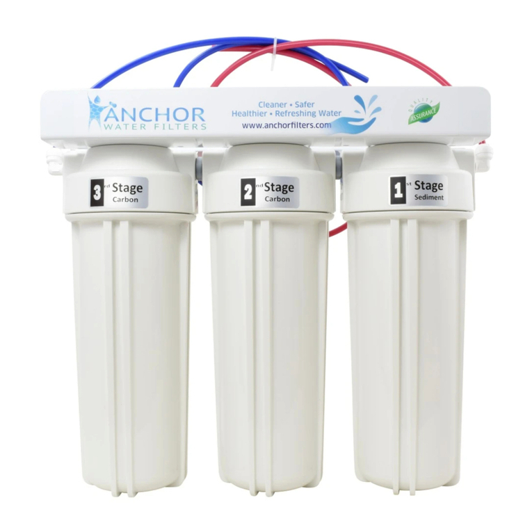
Anchor AF-4003 User manual

UNDER COUNTER
WATER FILTER SYSTEM
Quick Setup Guide
Model# AF-4003

Your box contains:
Filter
Assembly
Faucet Box
with
accessories
Feed Water
Adapter
Quick Fitting
Elbow
Connector
Red & blue
tubing Wrench Use Guide
2
Know your filter
Stage 1Stage 2
Stage 3
Specifications
Made with highest quality NSF approved components
ATTRIBUTE VALUE
Temperature Range 40°F -100°F
Service Flow 1.5 gpm
Rated Capacity 1500 gallons
Operating Pressure 40 psi - 90 psi
Dimensions 15 3/8"L x 14"H x 5 3/4"W

Red
Tubing
Blue
Tubing
Faucet
A
B
Out In
3
Tools & Materials
Required for Installation
•Drill with 1/2″ Drill Bit (type as
required) if faucet needs to be
mounted
•Adjustable Open-End Wrenches
•Phillips and Flat Blade Screwdrivers
•Feed water supply valve and adapter
Installing your filter
IMPORTANT
-
- Install or store where it will not be exposed to temperatures below
freezing or exposed to any type of weather. Water freezing in the
system will damage it.
- Recommended installation is under the sink. However, the unit can
be installed in a remote location, up to 20 feet away from the sink.
Additional installation materials may be required.
-Be sure there is room underneath the sink to make the needed
connections.
-If installed under sink, leave enough tubing in place during
installation to be able to move unit to floor for ease at servicing and
making filter cartridge changes.
-Do not install on HOT WATER. Temperature of water supply to filter
system must be between minimum of 40°F and maximum of 90°F.
- The assembly can stand up in sink cabinet or can be hung on screws.
- Use PTFE (Teflon) tape for the fittings and do not overtighten.
Color Code For Tubing
Use the color-coded tubing to make connections as follows:
A. Red tubing connects water supply adapter to inlet side of the
assembly
B. Blue tubing connects the faucet to the outlet side of assembly

Faucet connection
pieces mapping
4
Installation
1. Faucet Installation
1) While selecting location for faucet, make sure faucet base fits flat
against the surface at the selected location so the gasket will seal, and
the faucet stud is accessible from below.
2) Slide Escutcheon chrome plate and large rubber gasket onto stem of
faucet and place faucet onto sink with stem going through the hole.
3) Place small rubber gasket, plastic washer, metal ss washer and star
lock washer over threaded stem of faucet and tighten locking nut
from under the counter surface to lock the faucet into place. DO NOT
OVER TIGHTEN.
4) Insert compression nut, plastic ferrule & tube insert into the blue
tubing as shown in image on next page. Now insert this end to the
faucet stud/stem hole from under the counter and tighten with
compression nut.
5) Other end of blue tubing from the faucet connects OUT of filter
assembly. See image on page 6.

5
Note: You may need to use Teflon tape on feed adapter to prevent leaks
a. Flex Line: Loosen nut and separate the cold-water riser tube from
faucet shank. Gently bend riser tube so that feed adapter fits into
faucet shank. Reinstall riser tube onto feed connector and tighten.
b. Solid-Copper Riser Tube: Follow same procedure as for flex tubing
above, except cut a piece of the riser tube so the feed adapter can
fit between faucet and riser tube.
3) Once the feed water adapter has been installed, connect the red/
orange tubing to the feed valve as in Figure 2.
Please see the following for flex line
and solid-copper riser installation.
2) Locate the feed-water adapter in
the installation kit.
Figure 2
Fits Both 1/2" NPT
and 3/8"
Compression Cold
Water Supply
2. Feed-Water Supply Installation
CAUTION: The water supply to the unit MUST be from the COLD-WATER
LINE. HOT WATER will severely damage the system.
1) Locate the cold water (angle) shut off valve (see picture below)
underneath the sink and turn it off. Open the cold-water faucet to
release the pressure. On single-handle kitchen faucets, the hot water
may have to be turned off to prevent
any hot water cross over. If
water continues to come out
of faucet with angled valve
turned off, the house main
must be turned off.

6
Connection to the Filter Assembly
Your filter assembly comes pre-installed with filter cartridges. You only
need to attach the quick fitting elbow connectors to inlet and outlet of
the filter assembly and attach feed water and faucet tubes to them.
Once connected, the system will be ready for use.
Remove the color-coded lock pins before inserting the tubes and
replace after you are done.
IN - Red Tube
▪Red tubing connects feed
water supply valve to inlet
side of assembly
OUT - Blue Tube
▪Blue tubing connects
faucet to the outlet side
of assembly
Startup Procedure
1. Check to see all connections are made.
2. Check that all sumps are secure using the housing wrench provided.
3. Slowly turn on water by turning the needle valve counterclockwise.
4. Handle of the faucet should be perpendicular to the spigot (closed).
5. Check for leaks.
WARNING: Before using filter system for the first time, the system must
be purged for several minutes to flush out black carbon fines. Initially,
the water may contain tiny air bubbles and taste slightly sweet this is
normal and harmless, and will clear up after flushing.

7
Replacing Filter Cartridge
Cartridge Information:
Stage Cartridge Model
# & Name Web URL Recommended
Maintenance Duration
Stage 1 Sediment
AF-1001
https://www.anchorfilt
ers.com/products/af-
1001-sediment-filter-
cartridge
Depends on water
condition and should be
checked at least at 6-
month intervals
Stage 2
& 3
Carbon Block
AF-1000
https://www.anchorfilt
ers.com/products/anc
hor-af-1000-carbon-
block-replacement-
filter
Should be changed
when there is an
unusual taste and/or
odor in the water or at
12-month intervals
This filter system contains replaceable components called
filter cartridges critical to efficiency of the system.
Replacement of these cartridges should be with one of
identical specifications to assure same efficiency and
contaminant reduction performance.
STEPS:
1. Shut off the feed water to the system by turning the knob on water
supply adapter clockwise until it stops.
2. Press down on faucet handle to relieve pressure.
3. Allow 2-3 minutes for pressure in the system to drop.
4. Remove the filter sumps with the housing wrench by turning the
sump to the left (counterclockwise). If the O- ring in the sump is
stretched or worn, it should be replaced to maintain a proper seal.
5. Remove the old filter and insert the new ones.
6. Replace the housing onto the cap by turning it to the right (clockwise)
until the O-ring makes firm contact. DO NOT OVER-TIGHTEN.
7. Turn on feed water to the system by turning the water supply adapter
knob counterclockwise.
8. Remember to flush the carbon fines.

All rights reserved. No part of this user guide may be
reproduced, distributed, or transmitted in any form or
by any means, including photocopying, recording, or
other electronic or mechanical methods, without the
prior written permission of Anchor USA.
SN00104EN2020
Register Your Product
Give yourself complete peace of mind and register product online to
receive timely reminders for filter replacements & for quick support.
IMPORTANT!
Run only cold water through the unit.
WARNING!
Do not use this filter for water that is
microbiologically unsafe or of unknown quality.
Technical Support
At Anchor USA, we are always here to help you. With 24-hour access to
our company contact web page, you can drop a message or email us
directly anytime, and one of our representatives will respond to your
query in less than 24-hrs.
Web: https://www.anchorfilters.com/contact-us
Email: support@anchorfilters.com
Register here:
https://www.anchorfilters.com/pr
oduct-registration
OR
Other manuals for AF-4003
1
Table of contents
Other Anchor Water Filtration System manuals
Popular Water Filtration System manuals by other brands

DH Instruments
DH Instruments 1-2 IN. FILTER KIT instruction sheet

Watts
Watts Premier WP4V-50 Installation, operation and maintenance manual

Eureka Forbes
Eureka Forbes AquaSure Aayush user manual

Millipore
Millipore milli-q user manual

AquaMaster
AquaMaster AMS700 Owner's manual and installation guide

Dover
Dover HYDRO AquaBlend Xtreme user manual