ANDELI TIG-250PL ACDC User manual

.
TIG-250PL ACDC
INVERTER AC/DC PULSED TIG WELDER
OPERATOR’S MANUAL

II
CONTENT
1 SAFETY.....................................................................................................................................................1
1.1 SIGNAL EXPLANATION............................................................................................................................ 1
1.2 ARC WELDING DAMAGE........................................................................................................................ 1
1.3 THE KNOWLEDGE OF ELECTRIC AND MAGNETIC FIELDS................................................................................5
2 SUMMARY...............................................................................................................................................6
2.1 BRIEF INTRODUCTION............................................................................................................................ 6
2.2 MODULE EXPLANATION..........................................................................................................................7
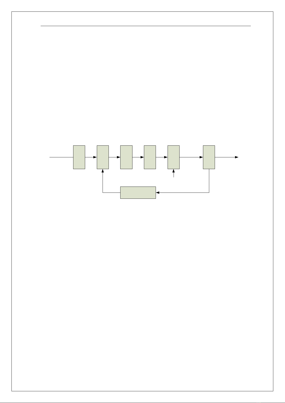
2.3 WORKING PRINCIPLE............................................................................................................................. 8
2.4 VOLT-AMPERE CHARACTERISTIC...............................................................................................................8
3 INSTALLATION AND ADJUSTMENT......................................................................................................... 9
3.1 PARAMETERS........................................................................................................................................9
3.2 DUTY CYCLE & OVER HEAT....................................................................................................................10
3.3 MOVEMENT AND PLACEMENT............................................................................................................... 11
3.4 POWER SUPPLY INPUT CONNECTION....................................................................................................... 11
3.5 ASSEMBLING THE EQUIPMENT (TIG)...................................................................................................... 12
4 OPERATION........................................................................................................................................... 13
4.1 LAYOUT FOR THE PANEL........................................................................................................................13
4.2 CONTROL PANEL................................................................................................................................. 14
4.4 ARGON ARC WELDING OPERATION........................................................................................................19
4.4 TIG welding (2T operation)........................................................................................................ 19
4.5 WELDING PARAMETERS........................................................................................................................21
4.5.1 Joint forms in TIG.................................................................................................................... 21
4.5.2 The explanation of welding quality.........................................................................................21
4.5.3 TIG Parameters Matching....................................................................................................... 21
4.6 OPERATION ENVIRONMENT...................................................................................................................24
4.7 OPERATION NOTICES........................................................................................................................... 25
5 MAINTENANCE & TROUBLESHOOTING................................................................................................25
5.1 MAINTENANCE................................................................................................................................... 25
5.2 TROUBLESHOOTING............................................................................................................................. 26
5.3 ELECTRICAL PRINCIPLE DRAWING............................................................................................................30
6 EXPLOSIVE DRAWING........................................................................................................................... 31

SAFETY
1
1 SAFETY
1.1 Signal Explanation
The above signals mean warning! Notice! Running parts and getting an electric shock or thermal
parts will take damage for your body or others. The corresponding notices are as follows. It is quite a
safe operation after taking several necessary protection measures.
1.2 Arc Welding Damage
The following signals and word explanations are to some damages for your body or others happening
on the welding operation. While seeing these, please remind of yourself or others to be dangerous.
Only ones who are trained professionally can install, debug, operate, maintain and repair the
equipment.
During the operation, non-concerned people should be lift, especially for children.
After shut off the machine power, please maintain and examine the equipment according to §5
because of the DC voltage existing in the electrolytic capacitors.
ELECTRIC SHOCK CAN KILL.
Never touch electrical parts.
Wear dry, hole-free gloves and clothes to insulate yourself.
Insulate yourself from work and ground using dry insulation. Make certain the insulation is large
enough to cover your full area of physical contact with work and ground.
Take carefully when using the equipment in small place, falling-off and wet circumstance.
Never close the machine power before installation and adjustment.
Ensure to install the equipment correctly and ground the work or metal to be welded to a good
electrical (earth) ground according to the operation manual.
The electrode and work (or ground) circuits are electrically “hot” when the welder is on. Do not touch
these “hot” parts with your bare skin or wet clothing. Wear dry, hole-free gloves to insulate hands.
In semiautomatic or automatic wire welding, the electrode, electrode reel, welding head, nozzle or

SAFETY
2
semiautomatic welding gun are also electrically “hot”.
Always be sure the work cable makes a good electrical connection with the metal being welded. The
connection should be as close as possible to the area being welded.
Maintain the electrode holder, work clamp, welding cable and welding machine in good, safe
operating condition. Replace damaged insulation.
Never dip the electrode in water for cooling.
Never simultaneously touch electrically “hot” parts of electrode holders connected to two welders
because voltage between the two can be the total of the open circuit voltage of both welders.
When working above floor level, use a safety belt to protect yourself from a fall should you get a
shock.
FUMES AND GASES CAN BE DANGEROUS.
Welding may produce fumes and gases hazardous to health. Avoid breathing these fumes and gases.
When welding, keep your head out of the fume. Use enough ventilation and/or exhaust at the arc to
keep fumes and gases away from the breathing zone. When welding with electrodes which require
special ventilation such as stainless or hard facing or on lead or cadmium plated steel and other metals
or coatings which produce highly toxic fumes, keep exposure as low as possible and below Threshold
Limit Values using local exhaust or mechanical ventilation. In confined spaces or in some circumstances,
outdoors, a respirator may be required. Additional precautions are also required when welding on
galvanized steel.
Do not weld in locations near chlorinated hydrocarbon vapors coming from degreasing, cleaning or
spraying operations. The heat and rays of the arc can react with solvent vapors to form phosgene, a
highly toxic gas, and other irritating products.
Shielding gases used for arc welding can displace air and cause injury or death. Always use enough
ventilation, especially in confined areas, to insure breathing air is safe.
Read and understand the manufacturer’s instructions for this equipment and the consumables to be
used, including the material safety data sheet and follow your employer’s safety practices.
ARC RAYS CAN BURN.
Use a shield with the proper filter and cover plates to protect your eyes from sparks and the rays of

SAFETY
3
the arc when welding or observing open arc welding.
Use suitable clothing made from durable flame-resistant material to protect your skin and that of
your helpers from the arc rays.
Protect other nearby personnel with suitable, non-flammable screening and /or warn them not to
watch the arc nor expose themselves to the arc rays or to hot spatter or metal.
SELF-PROTECTION
Keep all equipment safety guards, covers and devices in position and in good repair. Keep hands, hair,
clothing and tools away from V-belts, gears, fans and all other moving parts when starting, operating
or repairing equipment.
Do not put your hands near the engine fan. Do not attempt to override the governor or idler by
pushing on the throttle control rods while the engine is running.
DO NOT adds the fuel near an open flame welding arc or when the engine is
running. Stop the engine and allow it to cool before refueling to prevent spilled fuel from vaporizing on
contact with hot engine parts and igniting. Do not spill fuel when filling tank. If fuel is spilled, wipe it up
and do not start engine until fumes have been eliminated.
WELDING SPARKS can cause fire or explosion.
Remove fire hazards from the welding area. If this is not possible, cover them to prevent the welding
sparks from starting a fire. Remember that welding sparks and hot materials from welding can easily go
through small cracks and openings to adjacent areas. Avoid welding near hydraulic lines. Have a fire
extinguisher readily available.
Where compressed gases are to be used at the job site, special precautions should be used to
prevent hazardous situation.
When not welding, make certain no part of the electrode circuit is touching the work or ground.
Accidental contact can cause overheating and create a fire hazard.
Do not heat, cut or weld tanks, drums or containers until the proper steps have been taken to insure
that such procedures will not cause flammable or toxic vapors from substances inside. They can cause

SAFETY
4
an explosion even though they have been “cleaned”.
Vent hollow castings or containers before heating, cutting or welding. They may explode.
Sparks and spatter are thrown from the welding arc. Wear oil free protective garments such as
leather gloves, heavy shirt, cuff less trousers, high shoes and a cap over your hair. Wear ear plugs when
welding out of position or in confined places. Always wear safety glasses with side shields when in a
welding area.
Connect the work cable to the work as close to the welding area as practical. Work cables connected
to the building framework or other locations away from the welding area increase the possibility of the
welding current passing through lifting chains, crane cables or other alternate circuits. This can create
fire hazards or overheat lifting chains or cables until they fail.
Rotating parts may be dangerous.
Use only compressed gas cylinders containing the correct shielding gas for the process used and
properly operating regulators designed for the gas and pressure used. All hoses, fittings, etc. should be
suitable for the application and maintained in good condition.
Always keep cylinders in an upright position securely chained to an undercarriage or fixed support.
Cylinders should be located:
-Away from areas where they may be struck or subjected to physical damage.
-A safe distance from arc welding or cutting operations and any other source of heat, sparks, or
flame.
Never allow the electrode, electrode holder or any other electrically “hot” parts to touch a cylinder.
Keep your head and face away from the cylinder valve outlet when opening the cylinder valve.
Valve protection caps should always be in place and hand tight except when the cylinder is in use or
connected for use.

SAFETY
5
1.3 The knowledge of Electric and Magnetic Fields
Electric current flowing through any conductor causes localized Electric and Magnetic Fields (EMF).
The discuss on the effect of EMF is ongoing all the world. Up to now, no material evidences show that
EMF may have effects on health. However, the research on damage of EMF is still ongoing. Before any
conclusion, we should minimize exposure to EMF as few as possible.
In order to minimize EMF, we should use the following procedures:
Route the electrode and work cables together – Secure them with tape when possible.
All cables should be put away and far from the operator.
Never coil the power cable around your body.
Make sure welding machine and power cable to be far away from the operator as far as possible
according to the actual circumstance.
Connect the work cable to the workpiece as close as possible to the area being welded.
The people with heart-pacemaker should be away from the welding area.

SUMMARY
6
2 SUMMARY
2.1 Brief Introduction
TIG-250PL AC/DC welding machine adopts the latest pulse width modulation (PWM) technology
and insulated gate bipolar transistor (IGBT) power module, which can change work frequency to
medium frequency so as to replace the traditional hulking work frequency transformer with the
cabinet medium frequency transformer. Thus, it is characterized with portable, small size, light weight,
low consumption and etc.
The parameters of TIG-250PL AC/DC on the front panel all can be adjusted continuously and
steplessly, such as start current, crater arc current, welding current, base current, duty ratio, upslope
time, downslope time, pre-gas, post-gas, pulse frequency, AC frequency, balance, hot start, arc force
and arc length etc. When welding, it takes high frequency and high voltage for arc igniting to ensure
the success ratio of igniting arc.
TIG-250PL AC/DC Characteristics:
MCU control system , responds immediately to any changes.
High frequency and high voltage for arc igniting to ensure the success ratio of igniting arc, the
reverse polarity ignition ensures good ignition behaviour in TIG-AC welding.
Avoid AC arc-break with special means, even if arc-break occurs the HF will keep the arc stable.
Pedal control the welding current.
TIG/DC operation,If the tungesten electrode touches the workpiece when welding, the current
will drop to short-circuit current to protect tungsten.
Intelligent protection: over-voltage, over-current, over-heat, when the problems listed before
occurred, the alarm lamp on the front panel will be on and the output current will be cut off. It
can self-protect and prolong the using life.
Double purposes : AC inverter TIG and DC inverter TIG, Excellent performance on Al-alloy 、
carbon steel、stainless steel、titanium.
According to choosing the front panel functions, the following six welding ways can be realized.
DC TIG
DC Pulse TIG

SUMMARY
7
AC TIG
AC Pulse TIG
1.For DC TIG, DCEP is used normally (workpiece connected to positive polarity, while torch
connected to negative polarity). This connection has many characters, such as stable welding arc,
low tungsten pole loss, more welding current, narrow and deep weld;
2.For AC TIG (rectangle wave), arc is more stable than Sine AC TIG. At the same time, you can not
only obtain the max penetration and the min tungsten pole loss, but also obtain better clearance
effect.
3.DC Pulsed TIG has the following characters: 1) Pulse heating. Metal in Molten pool has short
time on high temperature status and freezes quickly, which can reduce the possibility to produce
hot crack of the materials with thermal sensitivity. 2) The workpiece gets little heat. Arc energy is
focused. Be suitable for thin sheet and super thin sheet welding. 3) Exactly control heat input and
the size of the molten pool. The depth of penetration is even. Be suitable for welding by one side
and forming by two sides and all position welding for pipe. 4) High frequency arc can make metal
for microlite fabric, eliminate blowhole and improve the mechanical performance of the joint. 5)
High frequency arc is suitable for high welding speed to improve the productivity.
TIG-250PL series welding machine is suitable for all positions welding for various plates made of
stainless steel, carbon steel, alloyed steel, titanium, aluminium, magnesium, cuprum, etc, which is also
applied to pipe installment, mould mend, petrochemical, architecture decoration, car repair, bicycle,
handicraft and common manufacture.
PWM——Pulse-Width Modulation;
IGBT——Insulation Gate Bipolar Transistor
TIG——Tungsten Insert Gas welding
2.2 Module Explanation
The module explanation of arc welding machine must accord with the correlative prescripts of
National Standard GB10249. It is explained as the following

SUMMARY
8
2.3 Working Principle
The working principle of TIG-250PL welding machines is shown as the following figure.
Single-phase 220V work frequency AC is rectified into DC (about 312V), then is converted to medium
frequency AC (about 20KHz) by inverter device (IGBT module), after reducing voltage by medium
transformer (the main transformer) and rectifying by medium frequency rectifier (fast recovery diodes),
then is outputted DC or AC by selecting IGBT module. The circuit adopts current feedback control
technology to insure current output stably. Meanwhile, the welding current parameter can be adjusted
continuously and steplessly to meet with the requirements of welding craft.
Rectif
ier
Invert
er
Trans
forme
r
Rectif
ier
Hall
devic
e
Current feedback
control
Single-phase, AC DC AC DC
220V,50Hz
AC Invert
er
AC or DC
Control signal
AC or DC
2.4 Volt-Ampere Characteristic
TIG-250PL AC/DC welding machine has an excellent volt-ampere characteristic, whose graph is
shown as the following figure. The relation between the conventional rated loading voltage U2and the
conventional welding current I2is as follows:
When I2≤600A,U2=10+0.04I2(V); When I2>600A,U2=34(V).

INSTALLATION AND ADJUSTMENT
9
3 Installation and Adjustment
3.1 Parameters
Models
Parameters
TIG-250PL ACDC
Input power
1~220±10%,50Hz
Rated input current(A)
26(TIG)
Rated input power(KW)
5.7(TIG)
67
34
10
0 600 I2(A)
U2(V)
Working
point
Volt-ampere characteristic The relation between the
conventional loading
voltage and welding current

INSTALLATION AND ADJUSTMENT
10
Power factor
0.76
Max no-load voltage(V)
64
Adjustment range of
start current(A)
TIG
AC
DC
HF
LIFT
10~welding current
10~welding current
30~welding
current
Adjustment range of
welding current(A)
10~200
30~200
10~200
Adjustment range of
Crater arc current(A)
10~200
30~200
10~200
Adjustment range of
downslope time(S)
0~5
Pre-gas time(S)
0.1~1
Adjustment range of
post-gas time(S)
0.1~10
Clearance effect(%)
15~50
Efficiency
Duty cycle
AC
DC
25% 200A
25% 200A
60% 129A
60% 129A
100% 100A
100% 100A
Protection class
IP21S
Insulation class
H
Dimensions of Machine
(L×W×H)(mm)
380*206*274
Weight(Kg)
12.6
3.2 Duty cycle & Over heat
The letter “X” stands for duty cycle, which is defined as the proportion of the time that a
machine can work continuously within a certain time (10 minutes). The rated duty cycle means
the proportion of the time that a machine
can work continuously within 10 minutes
when it outputs the rated welding current.
The relation between the duty cycle
“X” and the output welding current “I” is
I(A)
0
100%
25%
100 200
XThe relation of the welding current and
duty cycle for WSME-200

INSTALLATION AND ADJUSTMENT
11
shown as the right figure.
If the welder is over-heat, the IGBT over-heat protection unit inside it will output an
instruction to cut output welding current, and brighten the over-heat pilot lamp on the front
panel. At this time, the machine should be relaxed for 15 minutes to cool the fan. When
operating the machine again, the welding output current or the duty cycle should be reduced.
3.3 Movement and placement
Please take care for the welder when moving it, and do not make it sloped.
It also can be moved by the handle on the top of the welder. Place the welder well when
moving it to the right position. When the machine gets to the destination, it needs to be fixed up
to avoid gliding.
When using forklift, its arm length must be long enough to reach the outside so as to ensure
lifting safely.
The movement may result in the potential danger or substantive hazard, so please make
sure that the machine is on the safe position before using it.
3.4 Power supply input connection
TIG-250PL welding machines’ power supply connects to 220V.
When the power supply voltage is over the safe work voltage, there are over voltage and
under voltage protection inside the welder, the alarm light will on, at the same time, the current
output will be cut off.
If the power supply voltage continually goes beyond the safe work voltage range, it will
shorten the welder life-span. The below measures can be used:
Change the power supply input net. Such as, connect the welder with the stable power
supply voltage of distributor;
Induce the machines using power supply in the same time;

INSTALLATION AND ADJUSTMENT
12
Set the voltage stabilization device in the front of power cable input.
3.5 Assembling the equipment (TIG)
Workpiece is connected to the positive electrode of welding machine, and welding torch is
connected to the negative electrode, which is called DC POSITIVE CONNECTION; otherwise,
that is called DC NEGATIVE CONNECTION. Generally, it is usually operated in DC POSITIVE
CONNECTION in TIG welding mode.
The control cable of torch switch consists of 2 wires, pedal control of 3 wires and the aero
socket has 14 leads.
Consumable parts for TIG torch, such as tungsten electrode、tip 、gas nozzle 、electrode
shield(short/long) , please enquire us by mail or phone according to the accessory codes.
When TIG-250PL welding machines are operated in HF ignition method, the ignition spark
can cause interferences in equipment near the welding machine. Be sure to take specially
safety precautions or shielding measures.

MAINTENANCE AND TROUBLESHOOTING
13
4 Operation
4.1 Layout for the panel
1Positive output The welder’s positive polarity output.
2Aero socket Is connected to torch switch control wire.
3Negative output The welder’s negative polarity output.
4Shield gas connector Is connected to the gas input pipe of torch.
5Power source switch Switch to “ON”, the welder is turned on, while switch to “OFF”, the
welder is turned off.
6Power source input To connect power source.
7Shield gas input joint To connect one head of the gas hose while the other head of which is
connected to argon gas cylinder.
8Fan It is used for cooling the components and parts inside the welder.

INSTALLATION AND ADJUSTMENT
14
4.2 Control panel
(8) Adjusting dial
(1) AC/DC selecting key
(2) Mode selecting key
(10) Cool HZ/Time
(11) Welding voltage/other parameter display
(9) Rod electrode welding key
(12) Welding current display
(6) Parameter selection key
(7) Parameter selection key
(3) Gas-test key
(4) The program to save
(5) Pulse key

INSTALLATION AND ADJUSTMENT
15
Overview
The key feature of the control panel is the logical way in which the controls are arranged. All the
main
parameters needed for day-to-day working can easily be
-selected with the keys
-altered with the adjusting dial
-shown on the display during welding.
The illustration below shows an overview of the main settings needed for day-to-day working,
using the
TIG-250PL control panel as an example. You will find a detailed description of these settings in
the following section.
(1) AC/DC selecting key
AC welding
DC welding
(2) Mode selecting key
2-step mode
COLD mode
(3) Gas-test key
Lights up when Gas-test key is pressed, after that gas will flow out for 15s. Press the key again to
stop the
gas flow before the 15s are up.
(4) The program to save
Press this button to save the program you want after setting it, and then use it next time.
(5) Pulse key
Lights up when Pulse key is pressed, Pulse has been selected.
(6) and (7) Parameter selection keys
If “2T mode” has been selected, it is possible to change parameter indicator by means of the
parameter
selection keys (6) and (7) while the welding operation in progress.
(8) Adjusting dial
If the parameter indicator lights up, then the selected parameter can be altered on adjusting dial.

MAINTENANCE AND TROUBLESHOOTING
16
Available parameters where 2T mode have been selected:
Pre-flow time
Unit S
Setting range 0.1—1
Factory setting 0.3
Start (No such function)
Upslope time
Unit S
Setting range 0—10
Factory setting 0
TIG :Welding current
Unit A
TIG-250 10—200 (TIG-DC);10—200 (TIG-AC-HF);30—200 (TIG-AC-LIFT);
Base :Base current
Unit A
TIG-250PL 10—200 (DC);10—200 (AC-HF);10—200 (AC-LIFT)
Important! Only selectable when “pulse key” has been pressed.
Suggestion! Ib and Iw can not differ greatly.
Width Ratio of pulse duration to base current duration
Unit %
Setting range 5—100
Factory setting 5
Important! Only selectable when “pulse key” has been pressed.
Hz: Pulse frequency
Unit Hz
Setting range 0.5—200
Factory setting 0.5
Important! Only selectable when “pulse key” has been pressed.
Dslope : Downslope time
Unit S
Setting range 0—10

MAINTENANCE AND TROUBLESHOOTING
17
Factory setting 0
Stop: Crater arc current (No such function)
Post-flow
Unit S
Setting range 0.1—10
Factory setting 3
Hz: AC frequency (only with TIG-AC)
Unit Hz
Setting range 50—250 (Iw<50A)
50—200 (50A≤Iw<100A)
50—150 (100A≤Iw<150A)
50—100 (150A≤Iw<200A)
Balance (only with TIG-AC)
Balance adjustment is mainly used to set the adjustment of eliminating metal-oxide (such as
Aluminium,
Magnesium and its alloy) while AC output.
Unit %
Setting range 15—50
Factory setting 15
(9) Welding voltage/other parameter display
Indicate the welding voltage or other parameter.
Before the start of welding, the right-hand display shows the pre-set value of Tpr, Tup, Dcy, Fp,
Tdown andTpo.
There is a 3s time-lag, open-circuit voltage is displayed after adjusting those parameters.

MAINTENANCE AND TROUBLESHOOTING
18
After the start of welding, the right-hand display shows the present actual value of the welding
voltage.
(10) Welding current display
Display the pre-set or the actual welding current value.
Before the start of welding, the left-hand display shows the pre-set current value of Is, Iw, Ib and
Ic.
After the start of welding, the left-hand display shows the present actual value of the welding
current.
The control panel indicates which position has been reached in the welding process by
brightening the light.
NOTE:
Only “Parameter selection keys” and “Adjusting dial” can be used in the welding process.
Table of contents
Popular Inverter manuals by other brands

Wagan
Wagan Elite 1000W user manual

LS
LS SV-xxx-iP5A-2 manual

Riello
Riello Design white Series Instructions for the installer and the technical service centre

Power One
Power One AURORA PVI-6000-OUT-US-W Installation and operation manual

Northern Lights
Northern Lights M673LD3 Assembly instructions

Pierenkemper
Pierenkemper Zapper K100 operating instructions