Andersen Windows & Doors 901724 User manual

1
Andersen Storm Door Division is a wholly owned subsidiary of Andersen Corporation. Andersen
Storm Door Division manufactures and supports the limited warranties for Andersen® and
EMCO® storm doors.“Andersen”and“EMCO”and all other marks where denoted are trademarks
of Andersen Corporation. ©2019 Andersen Corporation. All rights reserved.
for Andersen® 1-1/2” Self-Storing Storm Doors with Balanced
Retractable Insect Screen and Integrated Close System
Installation Guide
Andersen SDD, PO Box 853
Des Moines, IA 50306-0853
02-2019 r2 15043 Print in Color
Door Frame Assembly:
Rain Cap
Rain Cap Extender
Integrated Closer System
Latch Rail
Hinge Rail
Sweep
Handle Clip
Spacer Clips (2)
Bottom Spacer
Ventilating Window
Screw Covers (3)
Retractable Screen
Rain Cap End Plug (2)
Not Shown
Handle Set Kit
Installation Kit
Window Handle Kit
PARTS OVERVIEW
B
G
F
O
P
Q
D
I
AA
E
N
C
H
J
L
M
K
Figure 1
Your installation kit should contain the following
parts. However, in some door models, not all of the
parts will be used.
E
H
J
N
I
F
M
K
B
D
E
C
G
H
J
L
p/n 901724
I
Please Do Not Return Product to Store!
with any questions regarding installation, lost part replacement, or anything else related to your storm door purchase.
Read this entire guide before you begin your installation. If your abilities do not
match the requirements of this installation, contact an experienced contractor.
PLEASE call the storm door Solution Center at 1-800-933-3626,
L
C

2
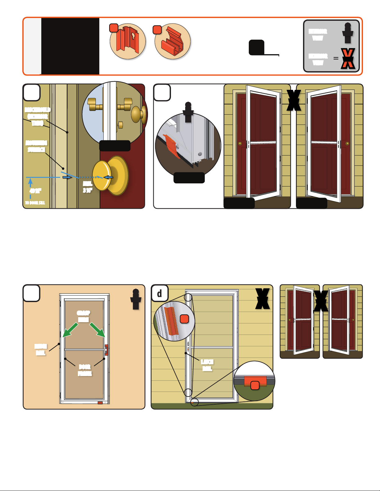
To install the storm door, you must verify that the opening width, height and mounting surface
are suitable size to properly install into the opening.
1. Measure the width at the top (W1), middle (W2), and bottom (W3) of the opening (see Figure 1).
Measure from the inside of the exterior trim. Utilizing the narrowest width, reference chart below.
2. Measure the height at the left and right of the opening, from the bottom of the exterior trim at the
top of opening down to the sill at the bottom of opening. Reference chart for height compliance.
Nominal Storm Door Widths*Opening Widths Opening Heights
36"x 80"35 ⁄" – 36 ⁄" 80" (80" – 80 ⁄")
34"x 80"33 ⁄" – 34 ⁄" 80" (80" – 80 ⁄")
32"x 80"31 ⁄" – 32 ⁄" 80" (80" – 80 ⁄")
30"x 80"29 ⁄" – 30 ⁄" 80" (80" – 80 ⁄")
3. Make sure that the exterior trim meets the mounting surface requirements. The assembly needs
a minimum of ¾" at surface on exterior trim face, 1" minimum depth of mounting surface (see
Figure 2). A minimum depth of 3 ⁄ inches for storm door handle clearance. (see Figure 3).
• ¾" minimum at surface on exterior trim face (see Figure 2)
• 1" minimum depth of mounting surface (see Figure 2)
• minimum depth of 3 ⁄ inches for storm door handle clearance (see Figure 3)
If your opening does not t within these dimensions, call the Solution Center at 1-800-933-3626,
as there may be a solution that will work for your opening. .
* Nominal storm doors sizes are listed. The actual storm door frame width and height will be less.
Example: A nominal size of 36” x 80” may have an actual storm door frame size of 35 ⁄” x 79 ⁄”.
Figure 1
W3
H1H1
W2
W1
Figure 2
Figure 3
1"MIN DEPTH
3 ⁄"MIN DEPTH
3/4"MIN
FLAT SURFACE
Verify that the exterior brickmould, trim board or casing (exterior trim) is rmly attached to the opening
structure and is a material that is suitable to suciently fasten the storm door to the door opening. The
storm door will sag over time if the mounting surface is not suciently fastened to the entryway.
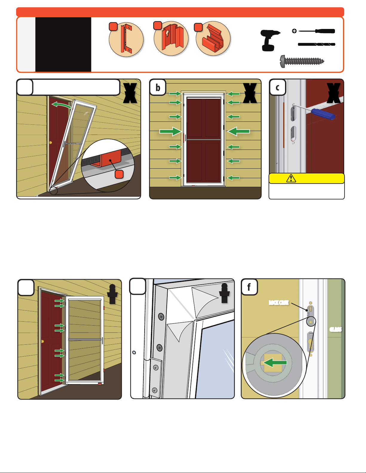
SAFETY FIRST: Please read and follow all Cautions and Warnings in this guide.
RECOMMENDED TOOLS
Drill
Safety Glasses
1/8 Drill Bit
!
!
1/2”
1/2”
1/2”
1”
1 1/2”
2”
1 1/2”
5/8”
5/8”
!
!
1/2”
1/2”
1/2”
1”
1 1/2”
2”
1 1/2”
5/8”
5/8”
Work Gloves
Pliers
The insect screen is intended for reasonable insect
control and not the retention of objects, persons, or
pets within the interior. The insect screen material
will not stop a person from falling through the door.
Follow manufacturers' instructions for hand and power
tools. Always wear safety glasses. Failure to do so could
result in injury, product or property damage.
Windows and doors can be heavy. Use safe lifting techniques and a reasonable number of people with enough
strength to lift, carry, and install window and door products. Heavier windows and doors will require mechanical
assistance. Failure to do so could result in injury, product or property damage.
Metal fasteners and components could corrode when exposed to preservative-
treated or re-retardent treated lumber. Use approved fasteners and components
to fasten window or door. Failure to do so could cause a failure resulting in injury,
product or property damage.
Fastener must attach to a structural framing member with a 1" minimum fastener
embedment. Failure to do so could result in injury, product or property damage.
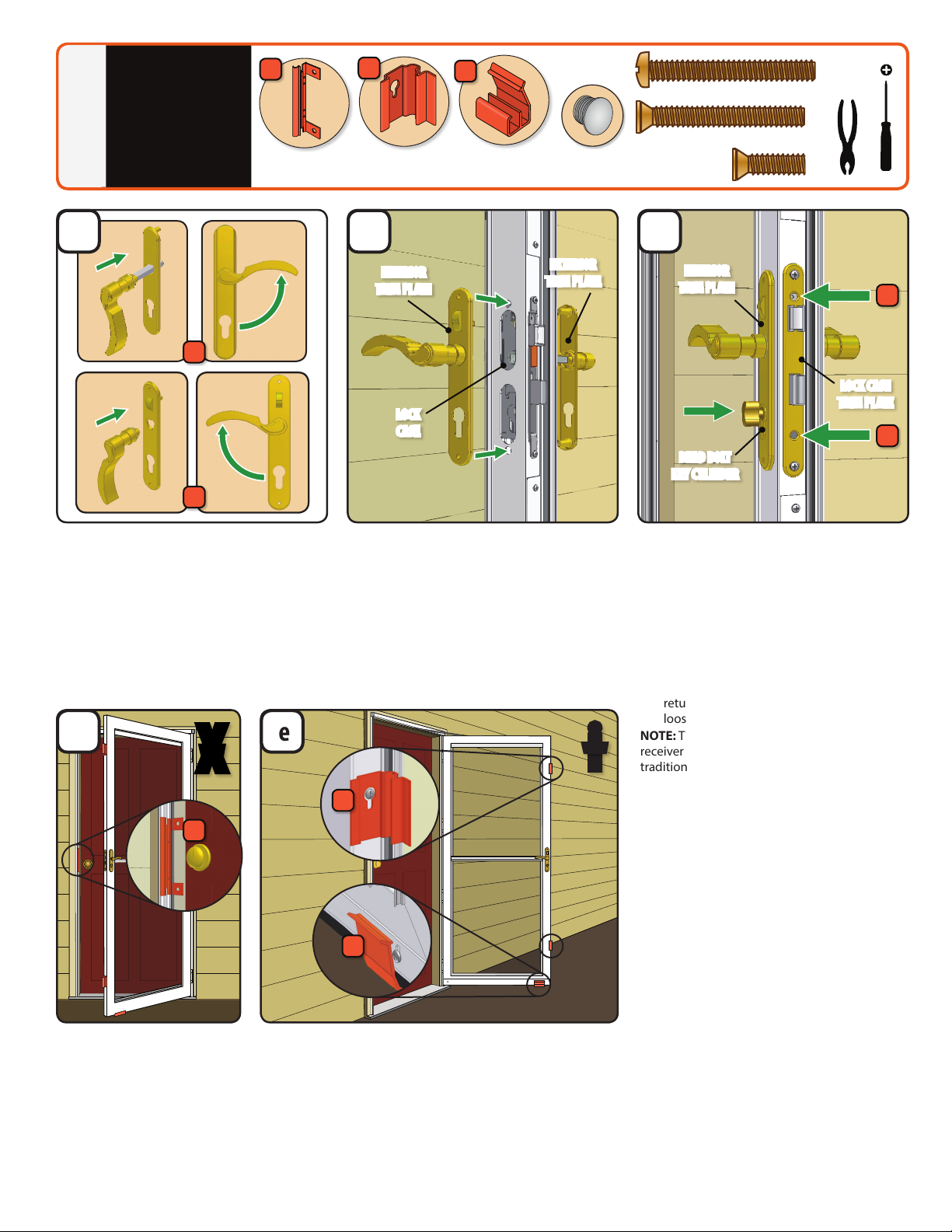
DO NOT remove screws that attached installation clips or gusset plates to window
or door frames. Doing so could result in injury, product or property damage.
Storm doors have small
parts. Small parts if
swallowed could pose a
choking hazard to young
children. Dispose of unused,
loose, or easily removed small
parts. Failure to do so could
result in injury.
Metal components of the entry and the storm door
may become hot when exposed to sunlight.
IMPORTANT
WARNING WARNING
WARNING WARNINGCAUTION
Major Injury / Death
Product or Property
Damage
Minor Injury
Procedure and Product
Information
This is the Safety Alert Symbol used to alert you to
potential injury hazards. Obey all safety messages that
follow this symbol to avoid possilbe injury or death.
WARNING
NOTICE
CAUTION
IMPORTANT
Signal Word and Consequence
COULD
Result in:
COULD
Result in:
COULD
Result in:
Tape Measure
!
!
1/2”
1/2”
1/2”
1”
1 1/2”
2”
1 1/2”
5/8”
5/8”
!
!
1/2”
1/2”
1/2”
1”
1 1/2”
2”
1 1/2”
5/8”
5/8”
Phillips
Screwdriver Straight head
Screwdriver
MEASURE - VERIFY MOUNTING SURFACE REQUIREMENTS AND MEASURE DOOR OPENING*
1

3
INSTALLATION
PREPARATION
2
b
a
1. Most homeowners prefer to have the storm door
handle on the same side as the entry door handle.
In shallow door openings, this can cause the two
handles to interfere (see Figure 4).
2. Check for potential interference by measuring up
from the Door Sill 40 ½". Measure in from mounting
surface on brickmould 3 ⁄". This is roughly the
location and depth of the storm door handle.
3. If you anticipate interference, purchase a storm door
hinged on the opposite side of your entry door.
In this step, you will conrm that your storm door hinges on the correct side.
1. To determine the exterior and interior of the door panel: at the bottom of the door,
the interior side has a sweep with screws (Figure 5). The exterior is the side without
a sweep and screws.
2. Left Handed (Figure 6): From the exterior, a left handed storm door will have the handle
holes on the left side of the storm door. See pages 4-8 for installation instructions.
3. Right Handed (Figure 7): From the exterior, a right handed storm door will have the handle
holes on the right side of the storm door. See pages 9-13 for installation instructions.
Figure 6 Figure 7
40 ½"
GRASP
HERE
c d
1. Remove door from carton, grasping it as shown.
Support door’s weight by the door frame, not by
hinge and latch rails.
2. Set aside rain cap extender and the screw covers
for use in a later step
Ensure all clips are properly attached.
1. With door standing from the exterior, ensure
latch rail is properly seated in orange spacer clips
(I), and ensure bottom spacer (J) is attached to
bottom of door and slid to handle side.
NOTE: See troubleshooting section at end of install
guide if bottom spacer becomes detached.
LEFT HAND
Proceed to
Page 4-8
RIGHT HAND
Proceed to
Page 9-13
Figure 5
i
VIEW
i
VIEW
X
VIEW
X
VIEW
TO DOOR SILL
X
VIEW
J
I
Tape Measure
MOUNTING
SURFACE
BRICKMOULD
EXTERIOR
TRIM
DOOR
FRAME
HINGE
RAIL
LATCH
RAIL
MIN.
3 ⁄"
Figure 4
Tools needed:
Bottom SpacerSpacer Clips
J
I=
=X
VIEW
i
VIEW
EXTERIOR
VIEW
INTERIOR
VIEW

4
1. While holding door in position, use 1/8” drill
bit from the installation kit to drill a hole in the
mounting surface through two pre-drilled holes
(indicated above with extra-large green arrows).
2. Fasten door to mounting surface using two 1”
screws.
3. Pre-drill holes in mounting surface through
remaining twelve holes in side rails, then
fasten door to mounting surface using
twelve 1” screws.
1. Unlatch upper and lower
handle side spacer clips by
pulling tab toward you.
2. Remove two handle hole
fasteners by inserting Phillips
screwdriver into handle hole
and rmly pressing them
out. Properly discard orange
handle fasteners.
3. Grasp edge of door and rmly
pull door open.
1. Using 1/8” drill bit, drill holes in door jamb
through holes in hinge rail.
2. Fasten hinge rail to door jamb using eight
1” screws. Do not overtighten screws.
1. Set bottom of door centered in opening. Make sure
orange bottom spacer (J) is sitting on door sill.
2. Tip top of door into opening while ensuring bottom
of door frame rests on orange spacer. TIP: Place foot
against door bottom while tipping top of door frame
assembly into opening.
3. Door frame assembly is properly seated in opening
when both latch rail and hinge rail are ush against
mounting surface, while hinge rail and bottom spacer
are resting on door sill. NOTE: The gap between top of
door and rain cap is intentionally uneven at this step.
Tools needed:
Handle Clip Bottom SpacerSpacer Clips
HANG HINGED
STORM DOOR
AND REMOVE
SPACER CLIPS
(Left Hand)
3
bc
d
For a Right Hand Installation, go to Page 9.
J
!
!
1/2”
1/2”
1/2”
1”
1 1/2”
2”
1 1/2”
5/8”
5/8”
HJ
I
1/8"
!
!
1/2”
1/2”
1/2”
1”
1 1/2”
2”
1 1/2”
5/8”
5/8”
1. Look into handle holes on door to make
sure lock case is oriented properly. Notch in
square spindle hole should be facing away
from glass panel.
TIP: If notch is not facing away from glass panel,
use handle and spindle to rotate spindle hole
into correct orientation.
f
1" x 22
#8
#10
#12
#6
3/4” Machine Pan Painted
1/2” SMS Pan
1/2” SMS Pan Painted
1/2” SMS Flathead
1/2” Self-Drill Pan
1/2” Self-Drill Pan Painted
3/4” Machine Flathead
7/8” Machine Pan Painted
1” SMS Pan
1” SMS Pan Painted
1” Machine Pan Painted
1-1/2” Machine Flathead
2” SMS Pan Painted
5/8” SMS Pan Painted
1-1/4” SMS Pan
X
VIEW X
VIEW X
VIEW
i
VIEW
1. If your door has clear protective lm, start
at the frame corners and remove the clear
protective lm from both the interior and
exterior of door frame.
ei
VIEW
GLASS
LOCK CASE
LEFT HAND HINGED INSTALLS ONLY
FOR RIGHT HAND HINGED INSTALL, SEE PG. 9
a
Do not open door by pulling on the
handle holes. Injury could result
CAUTION

5
1. Using pliers, grasp handle
clip (H) and pull away from
latch rail to remove.
2. Fill holes in latch rail with
color matched plugs
included in installation kit.
1. Remove spacer clips (I) by loosening but not removing screws.
2. Re-tighten screws. TIP: Use a screw driver to loosen and tighten
screws; a drill driver may strip the screw holes.
3. Remove bottom spacer (J) by pressing down on raised lip.
4. Properly discard all orange clips.
Handle Clip Bottom Spacer Color
Matched Plugs
Spacer Clips
de
HJ
I
Your storm door lock can be changed (re-keyed) to match your main door’s
handle set if it’s a Kwikset® (included) or a Schalge® (additional purchase
required). Many home improvement stores or locksmiths can make
duplicate keys.
“Kwikset”is a registered trademark of Newfry LLC.“Schlage”is a registered trademark of Schlage
Lock Company.
1. Install lock case trim plate onto lock case and
partially install 5/8” screw to allow movement.
2. Insert dead bolt key cylinder into lock case
and partially install 1 1/2” athead screw to
allow movement. Test deadbolt lock for proper
alignment.
3. Using a hand held screwdriver, tighten lock
case trim plate screws.
4. Tighten interior trim plate pan head screws.
5. Test handle operation. If handle does not
return to horizontal position, then lightly
loosen interior trim plate pan head screws.
NOTE: This door features an integrated latch
receiver in the latch rail, eliminating the need for a
traditional, separate strike plate.
1. Make sure the factory applied nylon washer
is in place at the base of both handles.
2. With trim plates not installed, insert handle
with spindle into outside exterior trim plate
(with Andersen logo) with lever pointing
down and rotate handle to secure it into the
trim plate.
3. Repeat for other handle without spindle
with inside interior trim plate (with slider).
1. With handle levers held horizontal, install
both handle assemblies onto door. Spindle
will pass through square hole in lock case
and into other handle. Attach interior and
exterior trim plates together using two
1 1/2” pan head screws. Partially install
screws to allow movement for alignment
in following steps.
INSTALL
HANDLE SET
(Left Hand)
4
c
b
5/8”
1-1/2” x 2
1-1/2”
i
VIEW
X
VIEW
H
J
I
2
3
1
2
a
#8
#10
#12
#6
3/4” Machine Pan Painted
1/2” SMS Pan
1/2” SMS Pan Painted
1/2” SMS Flathead
1/2” Self-Drill Pan
1/2” Self-Drill Pan Painted
3/4” Machine Flathead
7/8” Machine Pan Painted
1” SMS Pan
1” SMS Pan Painted
1” Machine Pan Painted
1-1/2” Machine Flathead
2” SMS Pan Painted
5/8” SMS Pan Painted
1-1/4” SMS Pan
!
!
1/2”
1/2”
1/2”
1”
1 1/2”
2”
1 1/2”
5/8”
5/8”
INTERIOR
TRIM PLATE
EXTERIOR
TRIM PLATE
DEAD BOLT
KEY CYLINDER
INTERIOR
TRIM PLATE
LOCK CASE
TRIM PLATE
LOCK
CASE
!
!
1/2”
1/2”
1/2”
1”
1 1/2”
2”
1 1/2”
5/8”
5/8”

6
i
VIEW
1. To attach window handle, located
in window handle kit (Q), rst lower
venting window so pre-drilled holes
are at a comfortable working height.
2. Align holes in window handle and
ventilating window frame, secure
with two 3/4" screws (provided in
window handle kit).
f
INSTALL RAIN CAP
EXTENDER, SCREW
COVERS, & WINDOW
HANDLE
(Left Hand)
5
L
If necessary, adjust the sweep (G).
1. If there is a gap between sweep ns and
door sill or if the sweep ns bind on door
sill when opening, adjust the sweep.
2. From interior of the panel, loosen the
sweep screws with a phillips screw driver.
Adjust the sweep up or down until the
sweep ns lightly come into contact with
the door sill.
3. Retighten the sweep screws.
e
DOOR SILL
SWEEP
i
VIEW
G
C
1. If there is a gap above your door, you will
need to install the rain cap extender (C).
If not needed, dispose of properly and skip
to step 5c.
2. Place the rain cap extender over the rain cap
as shown, with both ends centered over the
rain cap.
1. Using 1/8" drill bit, drill holes in brickmould
through holes in rain cap extender.
2. Fasten the rain cap extender to the mounting
surface using three 1" screws. Do not
overtighten screws.
NOTE: Be careful not to hit rain cap with drill
driver.
1. Install screw covers (L) into side rails and
rain cap extender (if installed). Insert side
of screw cover into the side of the screw
track. Press on other side to snap it into
screw track. Make sure they snap the entire
length of the channel.
a b c
X
VIEW
d
1. Install end covers into rain cap. Pressing round
button down on end cover (N), slide end cover
into rain cap until it is secured.
2. Repeat for other side.
N Q
Tools needed:
(optional)
!
!
1/2”
1/2”
1/2”
1”
1 1/2”
2”
1 1/2”
5/8”
5/8”
1/8"
!
!
1/2”
1/2”
1/2”
1”
1 1/2”
2”
1 1/2”
5/8”
5/8”
1" x 3
#8
#10
#12
#6
3/4” Machine Pan Painted
1/2” SMS Pan
1/2” SMS Pan Painted
1/2” SMS Flathead
1/2” Self-Drill Pan
1/2” Self-Drill Pan Painted
3/4” Machine Flathead
7/8” Machine Pan Painted
1” SMS Pan
1” SMS Pan Painted
1” Machine Pan Painted
1-1/2” Machine Flathead
2” SMS Pan Painted
5/8” SMS Pan Painted
1-1/4” SMS Pan
Rain Cap Extender
(optional)
Screw
Covers
End
Cover
Handle
Kit
SWEEP FINS
OPTIONAL OPTIONAL
L
L
C
N
Q

7
1. Open the door and then let it close.
Note the speed at which the door closes.
2. Use a at blade screwdriver to adjust the
closer to the desired speed. For a faster closing
speed, turn the adjustment screw to the left
(counterclockwise).
For a slower closing speed, turn the adjustment
screw to the right (clockwise).
3. Test the speed at which the door closes after
each adjustment. Adjust the screw to achieve
the desired door closing speed.
ADJUST
CLOSING
SPEED OF
DOOR
Closer and door shown
are for reference only.
6
Tools needed:
!
!
1/2”
1/2”
1/2”
1”
1 1/2”
2”
1 1/2”
5/8”
5/8”
a
Storm door will close more quickly when the entry door is open. To achieve the proper closing speed, you will need
to adjust the closer using the built-in adjustment screw. Check for safe closing speed with your entry door in both
the closed and open position. To prevent injury, make sure people and/or pets are completely through the opening
before allowing the storm door to close freely.
WARNING
i
VIEW

8
TROUBLESHOOTING
(Left Hand)
For additional help with these,
or any other installation steps,
please call our Solution Center
at 1-800-933-3626.
7
If your bottom spacer falls o or is out of
position prior to fastening the door the the
mounting surface:
1. Hook the clip on to the sweep
2. Rotate clip until it snaps over back of sweep.
3. Slide clip until it is touching sweep screw on
handle side of door.
If the glass area behind the sill glass ller strip at bottom of door needs cleaning:
1. With a small hook shaped object like a hex wrench, slide the hooked end into the
slot at either end of the glass ller strip and rotate so hook is under the strip.
2. Lift up and remove the glass ller strip from the channel allowing access to clean
the glass and channel below the ller.
3. Align the slot in the corner of the glass and tip the glass ller strip back into place.
If handle binds or doesn’t spring back:
1. Slightly loosen trim plate screws (A).
2. Test handle set. If handle moves freely,
you’re done.
3. If it still binds: Slightly loosen key cylinder
and lock case plate screws (B).
If door isn’t latching onto latch rail:
1. Remove screw cover from latch rail (if
installed).
2. Remove six 1”screws from latch rail.
3. Push latch rail toward door frame until latch
falls into opening in latch rail.
4. If you can see holes in mounting surface
through holes in latch rail, you will need
to drill new holes in latch rail. Use 1/8” drill
bit to drill holes 1” above or below existing
holes.
5. Fasten latch rail to mounting surface using
six 1” screws.
6. Reinstall screw cover (see step 5c).
bca
d
!
!
1/2”
1/2”
1/2”
1”
1 1/2”
2”
1 1/2”
5/8”
5/8”
1/8”
!
!
1/2”
1/2”
1/2”
1”
1 1/2”
2”
1 1/2”
5/8”
5/8”
Tools needed:
J
X
VIEW
AB
i
VIEW
i
VIEW
X
VIEW

9
1. While holding door in position, use 1/8” drill
bit from the installation kit to drill a hole in the
mounting surface through two pre-drilled holes
(indicated above with extra-large green arrows).
2. Fasten door to mounting surface using two 1”
screws.
3. Pre-drill holes in mounting surface through
remaining twelve holes in side rails, then fasten
door to mounting surface using twelve 1”
screws.
1. Unlatch upper and lower
handle side spacer clips by
pulling tab toward you.
2. Remove two handle hole
fasteners by inserting Phillips
screwdriver into handle hole
and rmly pressing them
out. Properly discard orange
handle fasteners.
3. Grasp edge of door and rmly
pull door open.
1. Using 1/8” drill bit, drill holes in door jamb
through holes in hinge rail.
2. Fasten hinge rail to door jamb using eight
1” screws. Do not overtighten screws.
1. Set bottom of door centered in opening. Make sure
orange bottom spacer (J) is sitting on door sill.
2. Tip top of door into opening while ensuring bottom
of door frame rests on orange spacer. TIP: Place foot
against door bottom while tipping top of door frame
assembly into opening.
3. Door frame assembly is properly seated in opening
when both latch rail and hinge rail are ush against
mounting surface, while hinge rail and bottom spacer
are resting on door sill. NOTE: The gap between top of
door and rain cap is intentionally uneven at this step.
Tools needed:
Handle Clip Bottom SpacerSpacer Clips
HANG HINGED
STORM DOOR
AND REMOVE
SPACER CLIPS
(Right Hand)
8
bc
d
For a Left Hand Installation, go to Page 4.
J
!
!
1/2”
1/2”
1/2”
1”
1 1/2”
2”
1 1/2”
5/8”
5/8”
HJ
I
1/8"
!
!
1/2”
1/2”
1/2”
1”
1 1/2”
2”
1 1/2”
5/8”
5/8”
1. Look into handle holes on door to make
sure lock case is oriented properly. Notch in
square spindle hole should be facing away
from glass panel.
TIP: If notch is not facing away from glass panel,
use handle and spindle to rotate spindle hole
into correct orientation.
f
1" x 22
#8
#10
#12
#6
3/4” Machine Pan Painted
1/2” SMS Pan
1/2” SMS Pan Painted
1/2” SMS Flathead
1/2” Self-Drill Pan
1/2” Self-Drill Pan Painted
3/4” Machine Flathead
7/8” Machine Pan Painted
1” SMS Pan
1” SMS Pan Painted
1” Machine Pan Painted
1-1/2” Machine Flathead
2” SMS Pan Painted
5/8” SMS Pan Painted
1-1/4” SMS Pan
X
VIEW X
VIEW X
VIEW
i
VIEW
1. If your door has clear protective lm, start
at the frame corners and remove the clear
protective lm from both the interior and
exterior of door frame.
ei
VIEW
GLASS
LOCK CASE
RIGHT HAND HINGED INSTALLS ONLY
FOR LEFT HAND HINGED INSTALL, SEE PG. 4
a
Do not open door by pulling on the
handle holes. Injury could result
CAUTION

10
1. Using pliers, grasp handle
clip (H) and pull away from
latch rail to remove.
2. Fill holes in latch rail with
color matched plugs
included in installation kit.
1. Remove spacer clips (I) by loosening but not removing screws.
2. Re-tighten screws. TIP: Use a screw driver to loosen and tighten
screws; a drill driver may strip the screw holes.
3. Remove bottom spacer (J) by pressing down on raised lip.
4. Properly discard all orange clips.
de
Your storm door lock can be changed (re-keyed) to match your main door’s
handle set if it’s a Kwikset® (included) or a Schalge® (additional purchase
required). Many home improvement stores or locksmiths can make
duplicate keys.
“Kwikset”is a registered trademark of Newfry LLC.“Schlage”is a registered trademark of Schlage
Lock Company.
1. Install lock case trim plate onto lock case and
partially install 5/8” screw to allow movement.
2. Insert dead bolt key cylinder into lock case
and partially install 1 1/2” athead screw to
allow movement. Test deadbolt lock for proper
alignment.
3. Using a hand held screwdriver, tighten lock
case trim plate screws.
4. Tighten interior trim plate pan head screws.
5. Test handle operation. If handle does not
return to horizontal position, then lightly
loosen interior trim plate pan head screws.
NOTE: This door features an integrated latch
receiver in the latch rail, eliminating the need for a
traditional, separate strike plate.
1. Make sure the factory applied nylon washer
is in place at the base of both handles.
2. With trim plates not installed, insert handle
with spindle into outside exterior trim plate
(with Andersen logo) with lever pointing
down and rotate handle to secure it into the
trim plate.
3. Repeat for other handle without spindle
with inside interior trim plate (with slider).
1. With handle levers held horizontal, install
both handle assemblies onto door. Spindle
will pass through square hole in lock case
and into other handle. Attach interior and
exterior trim plates together using two
1 1/2” pan head screws. Partially install
screws to allow movement for alignment
in following steps.
c
b
i
VIEW
X
VIEW
H
J
I
2
3
1
2
a
INTERIOR
TRIM PLATE
EXTERIOR
TRIM PLATE
DEAD BOLT
KEY CYLINDER
INTERIOR
TRIM PLATE
LOCK CASE
TRIM PLATE
LOCK
CASE
Handle Clip Bottom Spacer Color
Matched Plugs
Spacer Clips
HJ
I
INSTALL
HANDLE SET
(Right Hand)
9
5/8”
1-1/2” x 2
1-1/2”
#8
#10
#12
#6
3/4” Machine Pan Painted
1/2” SMS Pan
1/2” SMS Pan Painted
1/2” SMS Flathead
1/2” Self-Drill Pan
1/2” Self-Drill Pan Painted
3/4” Machine Flathead
7/8” Machine Pan Painted
1” SMS Pan
1” SMS Pan Painted
1” Machine Pan Painted
1-1/2” Machine Flathead
2” SMS Pan Painted
5/8” SMS Pan Painted
1-1/4” SMS Pan
!
!
1/2”
1/2”
1/2”
1”
1 1/2”
2”
1 1/2”
5/8”
5/8”
!
!
1/2”
1/2”
1/2”
1”
1 1/2”
2”
1 1/2”
5/8”
5/8”

11
If necessary, adjust the sweep (G).
1. If there is a gap between sweep ns and
door sill or if the sweep ns bind on door
sill when opening, adjust the sweep.
2. From interior of the panel, loosen the
sweep screws with a phillips screw driver.
Adjust the sweep up or down until the
sweep ns lightly come into contact with
the door sill.
3. Retighten the sweep screws.
e
DOOR SILL
SWEEP
i
VIEW
G
1. If there is a gap above your door, you will
need to install the rain cap extender (C).
If not needed, dispose of properly and skip
to step 5c.
2. Place the rain cap extender over the rain cap
as shown, with both ends centered over the
rain cap.
1. Using 1/8" drill bit, drill holes in brickmould
through holes in rain cap extender.
2. Fasten the rain cap extender to the mounting
surface using three 1" screws. Do not
overtighten screws.
NOTE: Be careful not to hit rain cap with drill
driver.
1. Install screw covers (L) into side rails and
rain cap extender (if installed). Insert side
of screw cover into the side of the screw
track. Press on other side to snap it into
screw track. Make sure they snap the entire
length of the channel.
X
VIEW
d
1. Install end covers into rain cap. Pressing round
button down on end cover (N), slide end cover
into rain cap until it is secured.
2. Repeat for other side.
SWEEP FINS
INSTALL RAIN CAP
EXTENDER, SCREW
COVERS, & WINDOW
HANDLE
(Left Hand)
10
L
C
a b c
N Q
Tools needed:
(optional)
!
!
1/2”
1/2”
1/2”
1”
1 1/2”
2”
1 1/2”
5/8”
5/8”
1/8"
!
!
1/2”
1/2”
1/2”
1”
1 1/2”
2”
1 1/2”
5/8”
5/8”
1" x 3
#8
#10
#12
#6
3/4” Machine Pan Painted
1/2” SMS Pan
1/2” SMS Pan Painted
1/2” SMS Flathead
1/2” Self-Drill Pan
1/2” Self-Drill Pan Painted
3/4” Machine Flathead
7/8” Machine Pan Painted
1” SMS Pan
1” SMS Pan Painted
1” Machine Pan Painted
1-1/2” Machine Flathead
2” SMS Pan Painted
5/8” SMS Pan Painted
1-1/4” SMS Pan
Rain Cap Extender
(optional)
Screw
Covers
End
Cover
Handle
Kit
OPTIONAL OPTIONAL
i
VIEW
1. To attach window handle, located
in window handle kit (Q), rst lower
venting window so pre-drilled holes
are at a comfortable working height.
2. Align holes in window handle and
ventilating window frame, secure
with two 3/4" screws (provided in
window handle kit).
f
L
L
C
N
Q

12
ADJUST
CLOSING
SPEED OF
DOOR
Closer and door shown
are for reference only.
11
Tools needed:
!
!
1/2”
1/2”
1/2”
1”
1 1/2”
2”
1 1/2”
5/8”
5/8”
Storm door will close more quickly when the entry door is open. To achieve the proper closing speed, you will need
to adjust the closer using the built-in adjustment screw. Check for safe closing speed with your entry door in both
the closed and open position. To prevent injury, make sure people and/or pets are completely through the opening
before allowing the storm door to close freely.
WARNING
1. Open the door and then let it close.
Note the speed at which the door closes.
2. Use a at blade screwdriver to adjust the
closer to the desired speed. For a faster closing
speed, turn the adjustment screw to the left
(counterclockwise).
For a slower closing speed, turn the adjustment
screw to the right (clockwise).
3. Test the speed at which the door closes after
each adjustment. Adjust the screw to achieve
the desired door closing speed.
ai
VIEW

13
TROUBLESHOOTING
(Left Hand)
For additional help with these,
or any other installation steps,
please call our Solution Center
at 1-800-933-3626.
12
If the glass area behind the sill glass ller strip at bottom of door needs cleaning:
1. With a small hook shaped object like a hex wrench, slide the hooked end into the
slot at either end of the glass ller strip and rotate so hook is under the strip.
2. Lift up and remove the glass ller strip from the channel allowing access to clean
the glass and channel below the ller.
3. Align the slot in the corner of the glass and tip the glass ller strip back into place.
bca
d
!
!
1/2”
1/2”
1/2”
1”
1 1/2”
2”
1 1/2”
5/8”
5/8”
1/8”
!
!
1/2”
1/2”
1/2”
1”
1 1/2”
2”
1 1/2”
5/8”
5/8”
Tools needed:
J
X
VIEW
A
B
i
VIEW i
VIEW
X
VIEW
If your bottom spacer falls o or is out of
position prior to fastening the door the the
mounting surface:
1. Hook the clip on to the sweep
2. Rotate clip until it snaps over back of sweep.
3. Slide clip until it is touching sweep screw on
handle side of door.
If handle binds or doesn’t spring back:
1. Slightly loosen trim plate screws (A).
2. Test handle set. If handle moves freely,
you’re done.
3. If it still binds: Slightly loosen key cylinder
and lock case plate screws (B).
If door isn’t latching onto latch rail:
1. Remove screw cover from latch rail (if
installed).
2. Remove six 1”screws from latch rail.
3. Push latch rail toward door frame until latch
falls into opening in latch rail.
4. If you can see holes in mounting surface
through holes in latch rail, you will need
to drill new holes in latch rail. Use 1/8” drill
bit to drill holes 1” above or below existing
holes.
5. Fasten latch rail to mounting surface using
six 1” screws.
6. Reinstall screw cover (see step 5c).

14
CLEANING INSTRUCTIONS
LIMITED WARRANTIES
PRODUCT LIMITED WARRANTY
DOOR FRAME: EMCO Enterprises, Inc. (EMCO) warrants the door frame, hinges, and painted finish on Andersen® aluminum storm door products to be free from defects in manufacturing, materials, paint adhesion, or
workmanship, under normal use, for as long as the original consumer purchaser owns the home in which the door was initially installed.
COMPONENTS: EMCO warrants the non-glass and non-insect screen fabric components of Andersen® storm doors (including brass and nickel hardware finish and the mechanical functions of balancers, locksets, closers,
windows and insect screens) to be free from defects in manufacturing, materials and workmanship for a period of five (5) years from the date of original retail purchase or for as long as the original consumer purchaser
owns the home in which the door was initially installed, whichever is shorter. Insulated glass is also warranted for a period of five (5) years not to develop, under normal conditions, any material obstruction of vision
resulting from manufacturing defects or as a result of premature failure of the glass or hermetic seal.
In the event a door frame, hinges, insulated glass or a component fails as a result of a defect in manufacturing, materials or workmanship within the limited warranty period specified above, and upon written proof
of purchase, EMCO, at its option, will provide a replacement door frame, hinge, insulated glass unit and/or components without charge – installation is not included. Such replacement or repair is warranted for the
remainder of the original limited warranty period. Please locate the door serial number and written proof of purchase and contact EMCO Consumer Support at 1-800-933-3626. Warranty claims made one (1) year after
purchase are subject to a flat processing fee.
“OOPS-PROOF”INSTALLATION LIMITED WARRANTY
EMCO Enterprises, Inc. (EMCO) warrants that any part lost or mis-cut during the original installation of your Andersen storm door will be repaired or replaced at no additional charge within ninety (90) days of the date of
original purchase. This limited warranty will not apply if the part has been misused, abused or altered. Cutting parts not specified by the installation guide or mis-drilled parts are not included in this warranty.
In the event a part is lost or mis-cut within the limited warranty period, EMCO, at its option, will provide the appropriate replacement part – installation is not included. Please locate the door serial number and written
proof of purchase and contact EMCO Consumer Support at 1-800-933-3626.
GENERAL LIMITED WARRANTY INFORMATION
The limited warranties set forth in this document are the only express warranties (whether written or oral) applicable to Andersen® storm doors, and no one is authorized to modify or expand these limited warranties. All
warranty claims must be made during the applicable warranty periods.
ALL IMPLIED WARRANTIES INCLUDING MERCHANTABILITY AND FITNESS FOR A PARTICULAR PURPOSE ARE LIMITED TO THE APPLICABLE STATUTE OF LIMITATION, BUT IN NO CASE WILL EXTEND BEYOND THE TERM
OF THE LIMITED WARRANTIES SET FORTH ABOVE. EMCO EXCLUDES AND WILL NOT PAY FOR INCIDENTAL OR CONSEQUENTIAL DAMAGES, WHETHER ARISING OUT OF CONTRACT, TORT OR OTHERWISE, AND ITS
LIABILITY WILL IN ALL INSTANCES BE LIMITED TO THE REPAIR OR REPLACEMENT OF THE DEFECTIVE PRODUCT.
Some states do not allow the exclusion of incidental and consequential damages, or limitation of the duration of an implied warranty, so the above limitations or exclusions may not apply to you.
This limited warranty gives you specific legal rights, and you may also have other rights that may vary from state to state and in Canada.
What is NOT covered by this limited warranty: damage caused by 1) improper installation, maintenance, or use; 2) chemicals or airborne pollutants, such as salt or acid rain; 3) acts of God, including wind damage; 4)
products not manufactured by EMCO
EMCO Enterprises, Inc. is a wholly owned subsidiary of Andersen Corporation. EMCO manufactures Andersen® and EMCO® storm doors. EMCO supports the limited warranties covering Andersen® Storm and Screen Doors.
“Andersen”, “EMCO”and all other marks where denoted are trademarks of Andersen Corporation. ©2019 Andersen Corporation. All rights reserved.
Reprinted and effective as of February 2019.
Online Parts and Knowledge Store
Andersen is committed to helping you find parts quickly and easily for your Andersen® or EMCO® storm door. Use the site below and your serial number to find many of the most-common replacement parts
for your storm door.
This site also includes the Andersen Storm Door Learning Center. Whether you are trying to find other Andersen® or EMCO® products or you are looking for replacement part installation guides, or other care
and maintenance topics and tips, this is a great place to start.
parts.andersenstormdoors.com
WINDOW GLASS – The glass may be cleaned with any household glass cleaner. Keep glass cleaners away from all other components.
PLASTIC PARTS – Plastic door components may be cleaned by using a mild soap and water mixture and by gently rubbing the affected area. Do not use harsh abrasives or any product that contains chlorine.
ALUMINUM PARTS – Aluminum parts on the door may be cleaned by using a mild soap and water mixture and by gently rubbing the affected area. Mineral spirits may be used and will not harm the paint.This will
remove many items such as glue residue. Do not use harsh abrasives or any product that contains chlorine.
HANDLE COMPONENTS – BRASS and NICKEL handles and components may be cleaned by wiping them down periodically with a wet or dry cloth. OIL RUBBED BRONZE handles and components have a“living finish”
and no protective coating. With frequent handling and use, the natural oils from your hands will polish away the dark outer finish to expose the bronze beneath, often resulting in a two-tone appearance. They may be
cleaned by wiping them down periodically with a wet or dry cloth. PAINTED handles and components may be cleaned by using a mild soap and water mixture and by gently rubbing the affected area. Do not use harsh
abrasives or any product that contains chlorine.
SWEEPS – Sweeps may be cleaned with a mild solution of soap and water. Do not use harsh abrasives or any product that contains chlorine.
BRASS/NICKEL GLASS CLEANING – Brass and Nickel components may be cleaned with good quality cleaner; such as Brasso®.
Table of contents
Other Andersen Windows & Doors Insect Control Equipment manuals
Popular Insect Control Equipment manuals by other brands

Biogents
Biogents BG-Home instruction manual

BioSensory
BioSensory Mosquito 'Cognito operating instructions

DuPont Authentication
DuPont Authentication Velpar L H - 63377 manual

Ultrasound Tech
Ultrasound Tech ZeroBugs PLUS user guide

Manrose
Manrose MANPFK instructions

Lafferty
Lafferty 950721-TD Installation & operation instructions