Andersen LuminAire User manual

1
Emco Enterprises, Inc., is a wholly owned subsidiary of Andersen Corporation. Emco Enterprises, Inc.
manufactures and supports the limited warranties for Andersen®and EMCO®doors. “Andersen”,
“EMCO” and all other marks where denoted are trademarks of Andersen Corporation.
©2018 Andersen Corporation. All rights reserved.
Installation Guide
Please Do Not Return Product to Store!
with any questions regarding installation, lost part replacement, or anything else related to your retractable
insect screen purchase. Replacement parts can also be found at: parts.andersenstormdoors.com
Read this entire guide before you begin your installation. If your abilities do not
match the requirements of this installation, contact an experienced contractor.
PLEASE call the Storm Door Solution Center at 844-813-6664,
For installation help please visit www.AndersenLuminAire.com/install
PARTS OVERVIEW
2
3
1
1
2
2
Your replacement part should contain the following parts.
Andersen SDD, PO Box 853
Des Moines, IA 50306-0853
Rev 1-2018v1 Print in Color
p/n 900394
Replacement Latch Housing for Andersen®
LuminAire™Retractable Insect Screen Door
Latch Housing
End Caps (attached to ends of the housing)
Not Shown
Screw Pack containing:
• 1 inch #8 screws (qty 6)
• ½ inch #8 self-tapping screws (qty 3)
• ⁄ inch Drill Bit
• #2 Phillips Bit
D
To avoid product damage, be sure to place all parts of your retractable
insect screen on a soft non-abrasive surface such as carpet, drop cloth
placed on your lawn or cardboard.
NOTICE

2
1
REMOVAL #2 Phillips Bit
(provided)
Tools Recommended:
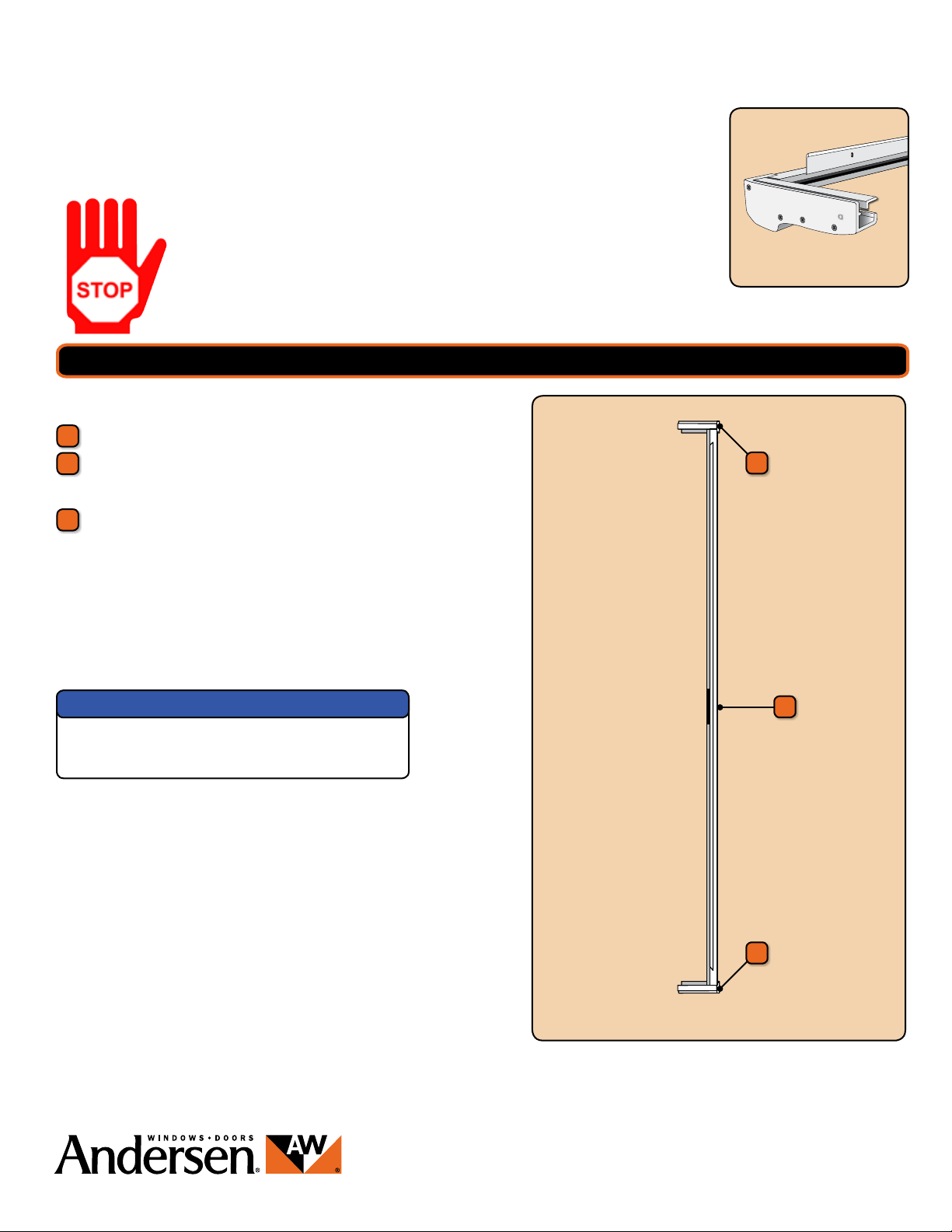
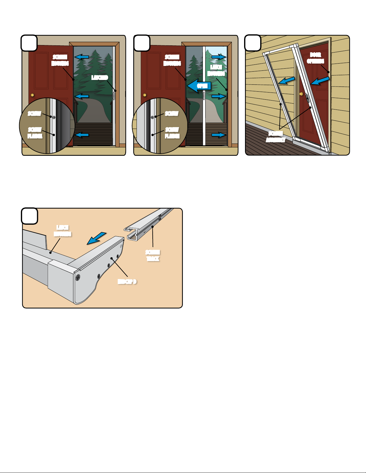
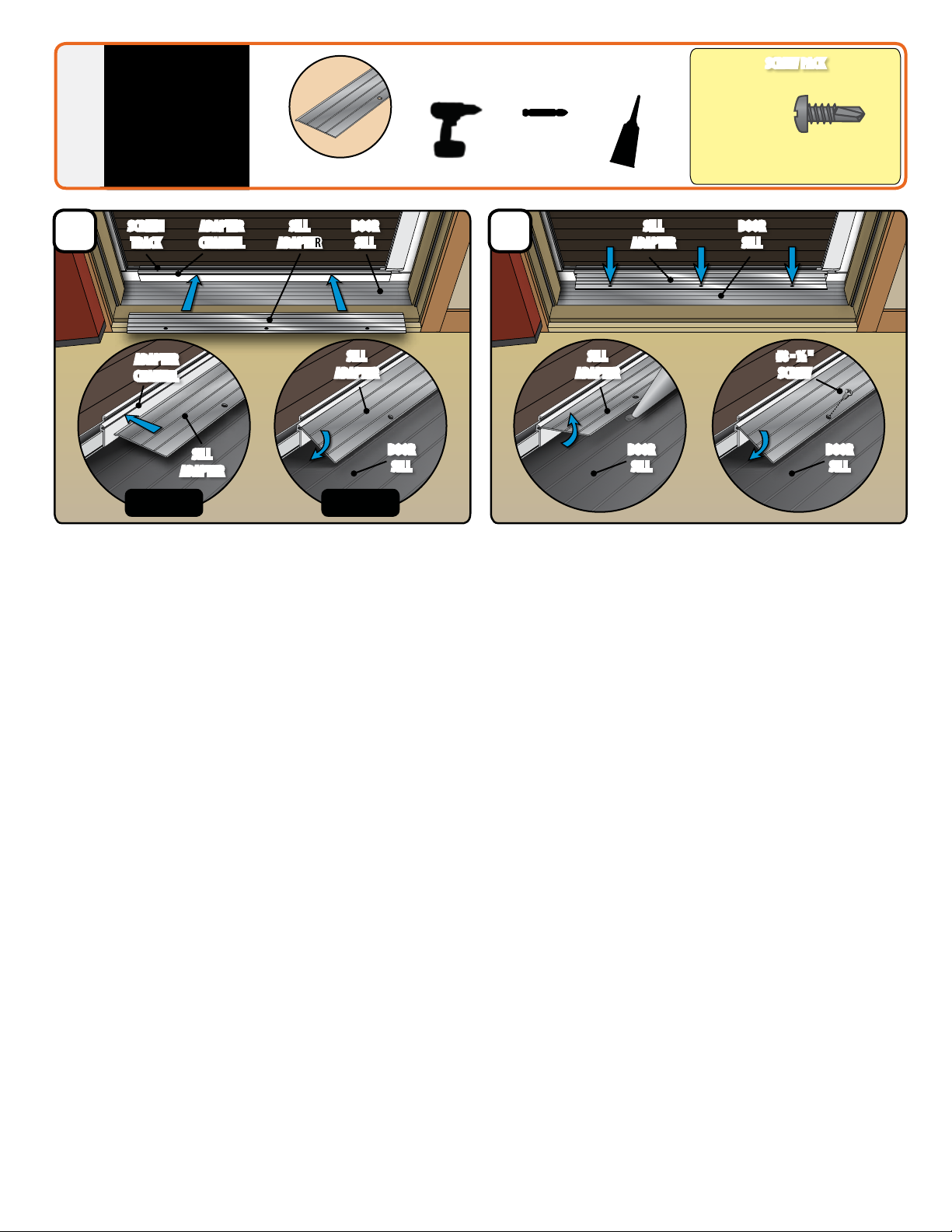
b1 From the interior of the screen assembly, remove the three screws
from the Sill Adapter.
b2 Rotate Sill Adapter up and pull out of Adapter Channel (see Figures 1 & 2).
b3 Save the Sill Adapter for reinstallation in future step.
b SILL
ADAPTER
SILL
ADAPTER
DOOR
SILL
ADAPTER
CHANNEL
SILL
ADAPTER
DOOR
SILL
Figure 2Figure 1
SAFETY FIRST: Please read and follow all Cautions and Warnings in this guide.
RECOMMENDED TOOLS
Drill
Safety Glasses Sealant
Screwdrivers
!
!
1/2”
1/2”
1/2”
1”
1 1/2”
2”
1 1/2”
5/8”
5/8”
Screwdriver
#2 Phillips Bit
(provided)
!
!
1/2”
1/2”
1/2”
1”
1 1/2”
2”
1 1/2”
5/8”
5/8”
Work Gloves
DOOR OPENING
HANDLE
DOOR OPENING
HANDLE
SCREEN HOUSINGSCREEN HOUSING
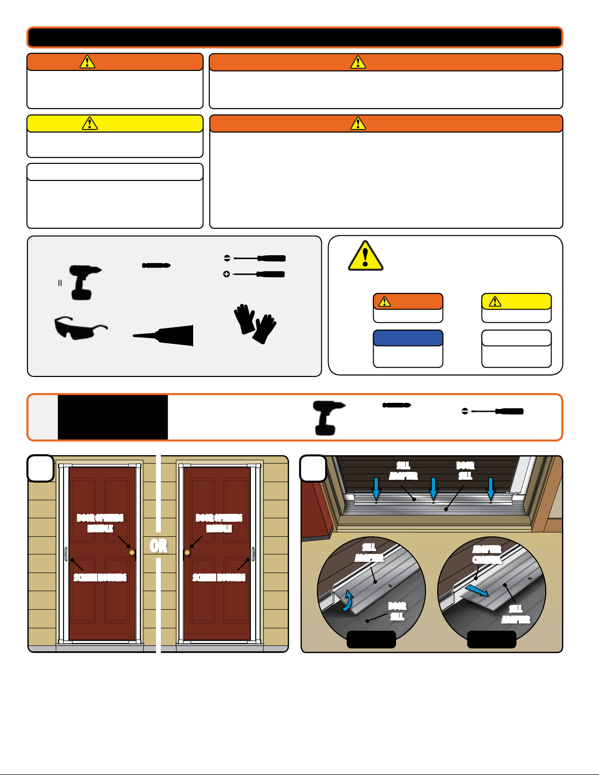
aFrom the exterior of the screen assembly, take note of the screen
assemblies orientation. This is the orientation the screen assembly
should be in when reinstalled.
a
OR
!
!
1/2”
1/2”
1/2”
1”
1 1/2”
2”
1 1/2”
5/8”
5/8”
!
!
1/2”
1/2”
1/2”
1”
1 1/2”
2”
1 1/2”
5/8”
5/8”
The retractable insect screen is intended for reasonable
insect control and not the retention of objects, persons,
or pets within the interior. The retractable insect screen
will not stop a person from falling through the door.
Follow manufacturers' instructions for hand and power
tools. Always wear safety glasses. Failure to do so could
result in injury, product or property damage.
Windows and doors can be heavy. Use safe lifting techniques and a reasonable number of people with enough
strength to lift, carry, and install window and door products. Heavier windows and doors will require mechanical
assistance. Failure to do so could result in injury, product or property damage.
Metal fasteners and components could corrode when exposed to preservative-treated or re-retardent treated
lumber. Use approved fasteners and components to fasten window or door. Failure to do so could cause a failure
resulting in injury, product or property damage.
Fastener must attach to a structural framing member with a 1" minimum fastener embedment. Failure to do so
could result in injury, product or property damage.
DO NOT remove screws that attached installation clips or gusset plates to window or door frames. Doing so could
result in injury, product or property damage.
Metal components of the retractable insect screen may
become hot when exposed to sunlight.
IMPORTANT
WARNING WARNING
WARNINGCAUTION
Major Injury / Death
Product or Property
Damage
Minor Injury
Procedure and Product
Information
This is the Safety Alert Symbol used to alert you to
potential injury hazards. Obey all safety messages that
follow this symbol to avoid possilbe injury or death.
WARNING
NOTICE
CAUTION
IMPORTANT
Signal Word and Consequence
COULD
Result in:
COULD
Result in:
COULD
Result in:

3
g Carefully slide the Latch Housing o of both Screen Tracks (sides B and D)
and dispose of Latch Housing properly.
D
D
f
ENDCAP D
SCREEN
TRACK
LATCH
HOUSING
d Unlatch and open the insect screen. Remove
the three screws on the Screw Flange on the
Latch Housing side, supporting the screen
assembly as needed.
e Carefully tip and lift Screen Assembly
out of Door Opening and place it at,
with the interior side facing up, on a
non-abrasive surface.
c From the interior of the screen assembly,
with the screen extended and in the latched
position, remove the three screws from the
Screw Flange on the Screen Housing side.
dc
LATCHED
SCREW
FLANGE
SCREW
FLANGE
SCREWSCREW
SCREEN
HOUSING LATCH
HOUSING
SCREEN
HOUSING
OPEN
SCREEN
ASSEMBLY
DOOR
OPENING
e
1 REMOVAL - Continued

4
REASSEMBLE
SCREEN
TRACKS &
HOUSINGS
2
D
a1 Leaving the screen in the retracted position, arrange the components so the letters marked on the Screen Tracks and the letters marked on the Endcaps
align (B to B, and D to D).
a2 Starting at corner D, slide the Receiving Tab on Endcap D inside the Screen Track (marked D). Make sure the Receiving Tab ts inside the Screen Track,
and the Screen Track slides into the Channel. (see “correct” above). Repeat the step for corner B. (Visit AndersenLuminAire.com/Install to view a video of this step.)
D
D
A
D
D
INTERIOR
LABEL
INTERIOR
LABEL
SCREEN
TRACK D
SCREEN
TRACK D
CHANNEL
(FOR SCREEN TRACK)
CHANNEL
(FOR SCREEN TRACK)
ENDCAP A
D
B
D
B
Latch Housing
KEY REFERENCES
A
D
D
CORRECT INCORRECT
RECEIVING TAB
(FITS INSIDE SCREEN TRACK)
RECEIVING TAB
(FITS INSIDE SCREEN TRACK)
RECEIVING TAB SHOULD NOT
BE OUTSIDE SCREEN TRACK
Screw Flanges
Receiving Tabs
Letter Labels
1
2
1
3
3
2
ALL ITEMS DURING THE ASSEMBLY STEPS
SHOULD BE LAYING FLAT ON THE GROUND
aReceiving Tabs on the Endcaps must
slide inside the Screen Track. Product
damage may occur if ReceivingTab is
forced outside the screen track.
NOTICE
Visit AndersenLuminAire.com/install
to view a video of this step.

5
#2 Phillips Bit
(provided)
PLACE AND
FASTEN
ASSEMBLY
INTO OPENING
3
DOOR OPENING
HANDLE
DOOR OPENING
HANDLE
SCREEN HOUSINGSCREEN HOUSING
Tools Recommended:
d Expand screen assembly by sliding Screen Housing side until the
Screw Flange is tight to the Mounting Surface.
c1 Verify the Latch Housing side Screw Flange is tight to Mounting Surface.
c2 Align the three holes on the Latch Housing side Screw Flange with the
three existing holes in the Mounting Surface.
c3 With three of the #8 - 1"screws, fasten Latch Housing side of screen
assembly to the Mounting Surface. (Be careful not to over tighten)
b1 The screen assembly may be narrower than your opening until fully
expanded in the following steps.
b2 Start by placing the Screen Assembly onto the exterior Trim Surface,
with the Screw Flanges extending into the Door Opening. Rest the
bottom of the screen assembly onto your sill or support blocking.
b3 Slide the screen assembly in the door opening until the Latch Housing
side Screw Flange is tight to the Mounting Surface.
a With the interior of the screen assembly facing the door opening,
rotate the assembly so the Screen Housing is on the opposite side
of the Door Opening Handle.
c
a
!
!
1/2”
1/2”
1/2”
1”
1 1/2”
2”
1 1/2”
5/8”
5/8”
#8-1"
(Qty 6)
SCREW PACK
#8
#10
#12
#6
3/4” Machine Pan Painted
1/2” SMS Pan
1/2” SMS Pan Painted
1/2” SMS Flathead
1/2” Self-Drill Pan
1/2” Self-Drill Pan Painted
3/4” Machine Flathead
7/8” Machine Pan Painted
1” SMS Pan
1” SMS Pan Painted
1” Machine Pan Painted
1-1/2” Machine Flathead
2” SMS Pan Painted
5/8” SMS Pan Painted
1-1/4” SMS Pan
SCREEN
ASSEMBLY
DOOR
OPENING
MOUNTING
SURFACE
MOUNTING
SURFACE
SCREW
FLANGE
SCREW
FLANGE
#8 - 1"
SCREW
SCREEN
HOUSING
LATCH
HOUSING
LATCH
HOUSING
d
TRIM
SURFACE
OR
b
SCREW
FLANGE
MOUNTING
SURFACE
EXPAND
EXPAND

6
e From the interior of the screen assembly, hold the Screen Housing side
Screw Flange against the Mounting Surface, extend the insect screen
across the assembly and latch.
f1 With the Screen Housing side Screw Flange tight to Mounting Surface,
align the three holes on the Screen Housing side Screw Flange with the
three existing holes in the Mounting Surface.
f2 With the three remaining #8 - 1"screws, fasten Screen Housing
to the Mounting Surface. (Be careful not to over tighten)
e f
LATCH
MOUNTING
SURFACE
MOUNTING
SURFACE
SCREW
FLANGE
SCREW
FLANGE
#8 - 1"
SCREW
SCREEN
HOUSING
SCREEN
HOUSING
3 PLACE AND FASTEN ASSEMBLY - Continued

7
PLACE AND
FASTEN SILL
ADAPTER #2 Phillips Bit
(provided)
Tools Recommended:
a1 Thoroughly clean the Door Sill.
a2 From the interior of screen assembly, position Sill Adapter with the
textured side up and screw holes in toward the interior of the home.
a3 Insert edge of the Sill Adapter into the Adapter Channel located on
the Screen Track (see Figure 1).
a4 Rotate the Sill Adapter down to the Door Sill to make sure the three
holes in the Sill Adapter align with the three existing holes in your
Door Sill. (see Figure 2).
b1 Lift Sill Adapter and apply sealant into the holes until sealant over ows
onto Door Sill surface.
b3 Rotate the Sill Adapter back down to the Door Sill and fasten using
three #8 - ½"Self-Tapping Screws. Cleanup excess sealant.
b
SCREW PACK
#8 - ½"
(Qty 3)
#8
#10
#12
#6
3/4” Machine Pan Painted
1/2” SMS Pan
1/2” SMS Pan Painted
1/2” SMS Flathead
1/2” Self-Drill Pan
1/2” Self-Drill Pan Painted
3/4” Machine Flathead
7/8” Machine Pan Painted
1” SMS Pan
1” SMS Pan Painted
1” Machine Pan Painted
1-1/2” Machine Flathead
2” SMS Pan Painted
5/8” SMS Pan Painted
1-1/4” SMS Pan
SCREEN
TRACK
SILL
ADAPTER
SILL
ADAPTER
SILL
ADAPTER
DOOR
SILL
DOOR
SILL
DOOR
SILL
ADAPTER
CHANNEL
ADAPTER
CHANNEL
SILL
ADAPTER
#8 - ½ "
SCREW
SILL
ADAPTER
DOOR
SILL
DOOR
SILL
4
Sill Adapter
a
Figure 1 Figure 2

8
1-844-813-6664
RETRACTABLE SCREEN DOOR
Other manuals for LuminAire
2
Table of contents
Other Andersen Insect Control Equipment manuals