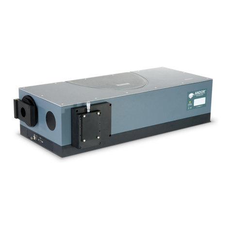
Andor Technology Mechelle User manual

2
Version 4.2 rev 06 Oct 2020
8.2 x 8.2 mm / 512 x 512 sensor
Lowest Noise Imaging EMCCD
Mechelle
TABLE OF CONTENTS
SECTION 1: INTRODUCTION .................................................................................... 16
1.1 TECHNICAL SUPPORT.......................................................................................................... 17
1.2 DISCLAIMER .......................................................................................................................... 18
1.3 COPYRIGHT AND PROTECTIVE NOTICES........................................................................... 18
1.4 TRADEMARKS AND PATENT INFORMATION....................................................................... 18
1.5 SUPPLIED COMPONENTS .................................................................................................... 19
1.5.1 Optional Components................................................................................................................................. 19
SECTION 2: PRODUCT OVERVIEW .......................................................................... 20
2.1 EXTERNAL COMPONENTS OF THE MECHELLE................................................................. 20
2.2 INTERNAL COMPONENTS OF THE MECHELLE.................................................................. 21
2.3 ENTRANCE APERTURE SLIT ................................................................................................ 22
2.3.1 Optional ST & FC bre adapters................................................................................................................. 22
2.3.2 Shutter ......................................................................................................................................................... 23
2.4 OPTIONAL CC52 COLLECTOR/COLLIMATOR WITH ALIGNMENT LASER ........................ 24
SECTION 3: INSTALLING THE MECHELLE SPECTROGRAPH ............................... 25
3.1 UNPACKING & HANDLING .................................................................................................... 25
3.2 ATTACHING THE CAMERA AND CAMERA ALIGNMENT PROCEDURE ............................. 25
3.3 CALIBRATION SOURCE......................................................................................................... 27
3.4 CONNECTING A USB BASED CAMERA ............................................................................... 28
3.5 INSTALLING ANDOR SOLIS SOFTWARE FOR WINDOWS (8, 8.1 AND 10) ........................ 29
3.6 NEW HARDWARE WIZARD ................................................................................................... 29
3.7 START-UP DIALOG................................................................................................................. 29
SECTION 4: USING THE MECHELLE ........................................................................ 30
4.1 LAUNCHING THE SOFTWARE .............................................................................................. 30
4.2 SETTING UP THE MECHELLE IN THE SOFTWARE ............................................................ 30
4.2.1 Extract Spectrum ........................................................................................................................................ 32
4.2.2 Order Lines.................................................................................................................................................. 32
4.2.3 Temperature and calibration....................................................................................................................... 32
4.2.4 Options (other)............................................................................................................................................. 32

3
Version 4.2 rev 06 Oct 2020
8.2 x 8.2 mm / 512 x 512 sensor
Lowest Noise Imaging EMCCD
Mechelle
4.3 ACQUIRING DATA ................................................................................................................. 35
4.4 WAVELENGTH CALIBRATION USING A MERCURY-ARGON SPECTRAL LAMP............... 36
4.5 CALIBRATION........................................................................................................................ 37
4.5.1 Calibration Files ...........................................................................................................................................39
4.5.2 Displaying Results........................................................................................................................................40
4.6 CROSSTALK ........................................................................................................................... 42
4.7 SUB-SPECTRUM ................................................................................................................... 43
4.8 ECHELLE GRATING EFFICIENCY ......................................................................................... 45
4.9 STANDARD LAMPS................................................................................................................ 46
4.10 GRATING EFFICIENCY CORRECTION PROCEDURE .......................................................... 47
4.10.1 REC Example 1 ..........................................................................................................................................51
4.10.2 REC Example 2 ..........................................................................................................................................52
4.11 RELATIVE EFFICIENCY CORRECTION ................................................................................. 53
4.11.1 Effect of Ambient Temperature on the Relative Efciency Correction ....................................................54
4.11.2 Relative Efciency Correction with Sub-Spectrum ..................................................................................54
SECTION 5: TROUBLESHOOTING ............................................................................ 55
SECTION 6: MAINTENANCE...................................................................................... 56
6.1 PURGING THE SHUTTER HOUSING .................................................................................... 57
6.2 EXCHANGING APERTURE SLIT OR FIBRE ADAPTERS ...................................................... 57
6.3 REPLACEMENT PARTS ......................................................................................................... 57
SECTION 7: TECHNICAL SPECIFICATIONS............................................................. 58
7.1 GENERAL SPECIFICATIONS ................................................................................................. 58
7.2 MECHANICAL SPECIFICATIONS .......................................................................................... 58
7.3 OPERATING & STORAGE CONDITIONS ............................................................................... 58
7.4
ME-OPT-0007 COLLIMATOR/COLLECTOR WITH ALIGNMENT LASER SPECIFICATIONS
...... 59
7.5 ME-OPT-0009 LASER ALIGNMENT MODULE SPECIFICATIONS ........................................ 59
7.6 SPECIFICATIONS FOR FIBRE OUTPUT ATTACHED TO ME-OPT-0009 LASER MODULE .... 59

4
Version 4.2 rev 06 Oct 2020
8.2 x 8.2 mm / 512 x 512 sensor
Lowest Noise Imaging EMCCD
Mechelle
APPENDIX A: MECHANICAL DRAWINGS ................................................................ 60
APPENDIX B: REFERENCE INFORMATION ............................................................. 61
APPENDIX C: OTHER INFORMATION ...................................................................... 65

5
Version 4.2 rev 06 Oct 2020
8.2 x 8.2 mm / 512 x 512 sensor
Lowest Noise Imaging EMCCD
Mechelle
Revision HistoRy
Version Released Description
1.0 12 Nov 2004 Initial Release
2.5 30 Sep 2005 -
2.6 21 Aug 2006 -
3.0 21 Jul 2011 -
3.1 31 Jul 2011 -
3.2 13 Dec 2011 -
4.0 07 Feb 2017 Updated to current format (all sections revised)
Information updated for USB camera models.
4.1 27 Feb 2020 Updated laser safety information.
4.2 06 Oct 2020 Updated laser safety information.
FutuRe veRsions oF tHe Manual
Changes are periodically made to the product and these will be incorporated into new editions of the manual. New
versions of Andor manuals are made available through MyAndor http://my.andor.com/login.aspx so please check for new
versions of the manual. If you do not have an account please register at http://my.andor.com/Register.aspx. If you nd an
error, or can suggest an improvement to this manual, please contact Andor Customer Support with details of the issue.

6
Version 4.2 rev 06 Oct 2020
8.2 x 8.2 mm / 512 x 512 sensor
Lowest Noise Imaging EMCCD
Mechelle
saFety and WaRning inFoRMation
PLEASE READ THIS INFORMATION FIRST
1. IMPORTANT: This product may come with the optional CC52 Collector/Collimator with Alignment Laser, which
emits laser radiation that is potentially hazardous, so please read the laser safety information following this
section very carefully.
2. IEC Technical Document IEC TR 60825-14 recommends the presence of a Laser Safety Ofcer (LSO)
depending on the laser class. However, national guidelines should be referred to.
3. Ensure that the ‘Working with Optical Fibres’ guidelines in this user guide is followed as these are easily
damaged.
4. To ensure correct and safe operation of this product, please read this guide before use and keep it in a safe
place for future reference.
5. If the equipment is used in a manner not specied by Andor, the protection provided by the equipment may be
impaired.
6. Before using the system, please follow and adhere to all warnings, safety, manual handling and operating
instructions located either on the product or in this guide.
7. The Mechelle a is a precision scientic instrument containing fragile components. Always handle with care.
8. This product is not designed to provide protection from ionising radiation. Any customer using this product in
such an application should provide their own protection.
9. The Andor Mechelle is for use in research laboratories and other controlled scientic environments.
10. This equipment has not been designed and manufactured for the medical diagnosis of patients.
11. Do not expose the product to extreme hot or cold temperatures.
12. Do not expose the product to open ames.
13. Do not allow objects to fall on the product.
14. Do not expose the product to moisture, wet, or spill liquids on the product. Do not store or place liquids on the
product. If spillage occurs on the product, switch off power immediately and wipe off with dry, lint-free cloth. If
any ingress has occurred or is suspected, unplug mains cable, do not use, and contact Andor service.
15. There are no user-serviceable parts in the product. If the enclosure is opened the warranty will be void.
16. Only use accessories that have been specied and approved for use with this product by Andor.

7
Version 4.2 rev 06 Oct 2020
8.2 x 8.2 mm / 512 x 512 sensor
Lowest Noise Imaging EMCCD
Mechelle
Manual Handling
Due to the delicate nature of some of the components within, care must be exercised when handling this product. Proper
manual handling techniques are important when unpacking and installing the system to ensure that the integrity of the
product is safeguarded and individuals involved are not exposed to unnecessary manual handling risks, such as:
• Lifting a load that is too heavy
• Poor posture or technique during lifting
• Dropping a load
• Lifting objects with sharp edges
sHipping and storage conditions
Unpacking and Inspection:
• Carefully unpack the unit and retain packaging to return equipment for servicing.
• If the equipment appears damaged in any way, return it to sales outlet in its original packaging.
No responsibility for damage arising from the use of non-approved packaging will be accepted.
• Ensure all items and accessories specied in the packing list are present.
If any items are missing, please contact your local sales representative.

8
Version 4.2 rev 06 Oct 2020
8.2 x 8.2 mm / 512 x 512 sensor
Lowest Noise Imaging EMCCD
Mechelle
special Warnings about lasers
CAUTION – USE OF CONTROLS OR ADJUSTMENTS OR PERFORMANCE OF PROCEDURES OTHER THAN
THOSE SPECIFIED HEREIN MAY RESULT IN HAZARDOUS RADIATION EXPOSURE
• This product includes lasers, or is designed to be upgraded with lasers, so you must be aware of the hazards
associated with the use of the powerful laser radiation that can be emitted by this product
• Laser radiation differs from ordinary light primarily because its optical power can be concentrated into a
narrow, low-divergence beam, whereas, for example, a standard light bulb diffuses its light in all directions and
thus spreads out its power. It’s a bit like the difference between walking outside on a sunny day versus having
the sun’s light concentrated on your skin using a magnifying glass
• Skin damage or deeper injury can be caused by lasers, but the eye is especially susceptible as laser light can
be collimated into a narrow beam that can enter the eye and permanently damage the retina with life-changing
consequences.
• Be aware that visible laser light is dangerous as well as invisible, that this laser product is not fully safe as you
usually have access to hazardous laser radiation. Laser safety for this type of product is about reducing risk,
rather than being able to eliminate it because access is required for the performance of this product
• Andor strongly recommend that all facilities have an established system for the safe use of lasers as per their
national regulations and occupational health and safety legislation. IEC TR 60285-14 Safety of laser products
– Part 14: A user’s guide and the American National Standard for the Safe Use of Lasers (ANSI Z136.1) are
standard references for good practice
use of tHe optional cc52 collector/colliMator WitH alignMent laser
The intended use of this laser product is only when the Laser Module is connected into the CC52 Collector/Collimator
(see Section 2.4). The Laser Module should only be powered when fully assembled in this conguration to reduce the
exposure to laser radiation. The Laser Module by itself and the Laser Module when connected just to the bre should
not be powered as the laser output in these two scenarios is unnecessary and is greater than that emitted by the CC52
Collector/Collimator.
If cleaning, assembling or disassembling this equipment, ensure that the power is disconnected.

9
Version 4.2 rev 06 Oct 2020
8.2 x 8.2 mm / 512 x 512 sensor
Lowest Noise Imaging EMCCD
Mechelle
guidelines for tHe safe operation of laser products
Please note that not all of the following guidance may apply to your product, e.g. you may not have invisible
lasers.
1. Never look into a laser beam either directly or indirectly.
2. Read the safety instructions supplied with all equipment in the system.
3. Ensure that the laser equipment is used in accordance with national guidelines.
4. Ensure all personnel requiring access to the product are fully trained in both using the product and the general
use of lasers.
5. Ensure users are familiar with the hazardous properties of lasers, especially that laser safety hazards differ
from those of normal light/radiation sources as they are highly-concentrated, very low divergence beams of
radiation.
6. Ensure end-users are familiar with the operation of the laser’s key switch control, interlocks, emission LEDs
and other safety features.
7. Restrict and control access to the area(s) where laser(s) are in use to those persons who are trained in the
dangers of lasers and trained on the safety precautions to be observed when working with lasers.
8. Ensure that all interlocks are connected and functioning correctly, where applicable.
9. Ensure suitable laser warning signs are prominently displayed in the area the system operates.
10. If the system is not in use, turn the laser off using the key switch, where applicable.
11. Do not attempt to disassemble the unit housing the lasers or any part of the system. If there is a problem
please contact Andor directly (see Section 1.1, ‘Technical Support’).
12. On a daily basis, or before every use, verify that the laser interlock circuit (if applicable) is working by
conrming that the laser emission indicator on the source(s) turns off when any of the following are done:
• The microscope ocular eyepieces are activated/engaged for viewing.
• The articulated transmitted light arm on inverted microscopes is tilted back from the functional vertical
position before using the system.
• Each beam splitter is removed from the unit.
• Any other interlocks on your system.
13. Fluorescent cards should be used to visually locate and indicate the output of invisible wavelengths at all
times, where applicable.
14. Additional precautions may need to be implemented as the necessary precautions will be specic to each
system installation, conguration and typical mode of use. The responsible Laser Safety Ofcer must assess
and implement the necessary precautions to avoid possible exposure to hazardous radiation during use.
15. We recommend that a copy of the latest edition of IEC 60285-1 Safety of laser products – Part 1: Equipment
classication and requirements is purchased by the Laser Safety Ofcer for reference, as well as IEC 60825-14
Safety of laser products – Part 14: A user’s guide.

10
Version 4.2 rev 06 Oct 2020
8.2 x 8.2 mm / 512 x 512 sensor
Lowest Noise Imaging EMCCD
Mechelle
laser class practical differences
The practical differences between the main classes are as follows as dened in IEC 60825-1 Annex C and Table F.2:
Class Overview* Eye Diffuse
Reections Skin Fire Hazard Detail †
1
Safe under
reasonably
foreseeable
conditions
Safe Safe Safe Safe
Laser products that are safe during use,
including long-term direct intrabeam
viewing, even when exposure occurs while
using telescopic optics.
2
Low power;
eye protection
normally
afforded by
aversion
& active
responses
Safe mometarily,
due to natural
aversion
behaviour, i.e.
you will close
your eye lids and
look way
Safe Safe Safe
Laser products that emit visible radiation
that are safe for momentary exposures but
can be hazardous for deliberate staring into
the beam.
The time base of 0,25 s is inherent in the
denition of the class and presumption
is that there is very low risk of injury for
momentary exposures that are somewhat
longer.
3R‡
Direct
intrabeam
viewing may
be hazardous
Not considered
intrinsically safe Safe Safe Safe
Not considered intrinsically safe, the risk is
limited because
– unintentional exposures would rarely
reect worst-case conditions of (e.g.)
beamalignment with a large pupil and
worst-case accommodation with the entire
beam energyentering the eye,
– of the inherent reduction factor (safety
margin) in the MPE,
– of natural aversion behaviour for exposure
to bright light for the case of visible
radiationand by the response to heating of
the cornea for far infrared radiation.The risk
of injury increases with exposure duration,
and exposure may be hazardous for ocular
exposure under worst-case conditions or
for intentional direct intrabeam viewing.

11
Version 4.2 rev 06 Oct 2020
8.2 x 8.2 mm / 512 x 512 sensor
Lowest Noise Imaging EMCCD
Mechelle
Class Overview* Eye Diffuse
Reections Skin Fire Hazard Detail †
3B
Direct intrabeam
viewing
normally
hazardous, i.e.
direct viewing of
beam with eye
Hazardous Normally safe
Lasers which
approach
the Class
3B AEL may
produce minor
skin injuries.
However, this
is only likely
if the beam
has a small
diameter or is
focussed.
Risk of igniting
ammable
materials for
same lasers
mentioned under
“Skin”
Laser products that are normally hazardous
when intrabeam ocular exposure occurs
(i.e. within the NOHD) including accidental
short time exposure
4
High power;
diffuse
reections may
be hazardous
Hazardous May be
hazardous Hazardous Often represent
a re hazard Everything above Class 3B
* See IEC 60825-1 Table F.2 †See IEC 60825-1 Annex C
‡CDRH Class IIIa is almost identical to Class 3R and 21CFR § 1040.10 (b) (8) describes the hazard as “depending upon the
irradiance, either an acute intrabeam viewing hazard or chronic viewing hazard, and an acute viewing hazard if viewed directly with
optical instruments”.
The following terms are dened as follows:
• Intrabeam ocular exposure: Getting your eye in the way of a laser beam.
• Nominal Ocular Hazard Distance (NOHD): Distance from the output aperture beyond which the beam irradiance
or radiant exposure remains below the appropriate corneal maximum permissible exposure (MPE).
• Accessible Emission Limit (AEL): Maximum accessible emission permitted within a particular class, i.e. the limit
at which one class transitions into another.
• Maximum Permissible Exposure (MPE): Level of laser radiation to which, under normal circumstances, persons
may be exposed without suffering adverse effects.

12
Version 4.2 rev 06 Oct 2020
8.2 x 8.2 mm / 512 x 512 sensor
Lowest Noise Imaging EMCCD
Mechelle
laser product safety standards
If your product contains lasers, it has been designed and manufactured to comply with the international laser product
safety standard IEC 60825-1 and the U.S. CDRH Regulation 21CFR § 1040.10 to reduce risk as far as is reasonably
practicable. Our Customer Support Team, where applicable, install the system according to the same standards, but if
there has been an agreement that you should install all or part of the laser product system, then you take responsibility
to install this according to the same standards.
eye protection
Eye Protection is not required for the safe use of the device as the only radiation observable (without intentional
misuse) is directionally stable, diffuse and highly divergent from the designated aperture which is static and labelled.
If eye protection is deemed desirable by the local Laser Safety Ofcer, Andor recommends the following products:
• 360 nm to 510 nm – Kentek KXP-4001 Spectacles
• 510 nm to 670 nm – Kentek KRA 6702 Spectacles
Working WitH optical fibres
1. Only service personnel authorised by Andor should remove or inspect bres as these are part of the installed
protective housing
2. The laser radiation passing through bres is potentially hazardous, so great care should be taken to avoid
exposure to this radiation
3. Ensure bre cables are not bent tightly or general mishandled as this may damage the internal optical bre
4. Ensure that the minimum bend radius is never exceeded when handling, which is recommended to be 300
mm
5. For transport or storage, bre cables should be coiled with a diameter of 300 mm or greater
6. Optical bres are prone to damage by bending local to the connector
7. The coupler is not designed to withstand pulling of the bre. If the bre is pulled, the system performance
could be compromised or the system may fail
8. Locate the laser source and any other connected devices within 2 m of each other so that the interconnecting
bres are not stretched, bent, or constrained

13
Version 4.2 rev 06 Oct 2020
8.2 x 8.2 mm / 512 x 512 sensor
Lowest Noise Imaging EMCCD
Mechelle
laser safety and product coMpliance labels
general syMbols
WARNING: Laser Radiation
This product meets the requirements of the applicable CE-marking directives of the EU
Me-opt-0007 colliMator/collector laser safety label
laser aperture
Note that as this is a Class 2 product, the laser aperture isn’t marked as stated in IEC 60825-1 § 7.8; however, it
should be clear that the laser is emitted from the large opening to the left of the “starburst” laser safety warning
symbol.
laser classification and Warning
This is a Class 2 product that will harm your eyes if you stare into it. See section on ‘Laser Class Practical Differences’
above. Do not stare into the beam.
radiation output
The ‘maximum output’ dened by IEC 60825-1 § 3.58 and § 7.9 is “the maximum accessible emission that is used to
determine the class of the laser product”. Note that this is as measured using a 7 mm aperture stop at 100 mm from
the accessible aperture of the collimator as per Condition 3, which simulates eye exposure. However, the total optical
power right at the output of the collimator is equal to the Classication Radiation Output marked on this product.
standards inforMation
IEC 60825-1:2014 has been used to determine the classication of the product and to provide the Radiation Output
marked on the product.

14
Version 4.2 rev 06 Oct 2020
8.2 x 8.2 mm / 512 x 512 sensor
Lowest Noise Imaging EMCCD
Mechelle
Me-opt-0009 laser alignMent Module safety label
laser aperture
The indicated position of the Laser Aperture is where the laser is emitted from this product.
laser classification and Warning
This is a Class 3R product that could harm your eyes if they are exposed to the beam. See section on ‘Laser Class
Practical Differences’ above for more details. Avoid direct eye exposure to the laser beam.
radiation output
The ‘maximum output’ dened by IEC 60825-1 § 3.58 and § 7.9 is “the maximum accessible emission that is used to
determine the class of the laser product”. Note that this is as measured using a 7 mm aperture stop at 100 mm from
the accessible aperture of the module as per Condition 3, which simulates eye exposure. However, the total optical
power right at the output of the module will be higher, typically 5.35 mW at the closest point of human contact.
standards inforMation
IEC 60825-1:2014 has been used to determine the classication of the product and to provide the Radiation Output
marked on the product.

15
Version 4.2 rev 06 Oct 2020
8.2 x 8.2 mm / 512 x 512 sensor
Lowest Noise Imaging EMCCD
Mechelle
Me-opt-0009 fibre output laser aperture safety label
As the bre can be disconnected from the ME-OPT-0007 Collimator/Collector, laser radiation can be emitted from the
output, so it is labelled as a ‘Laser Aperture’. Although the output would be classied as Class 2 because it is typically
0.15 mW under IEC 60825-1 Condition 3, this is superuous as it is attached to a Class 3R product, the Laser Module.
Note the total optical power right at the output of the bre is higher, typically 1.65 mW.
cdrH certification label
This self-certies that we comply with the U.S. CDRH laser regulations.

16
Version 4.2 rev 06 Oct 2020
8.2 x 8.2 mm / 512 x 512 sensor
Lowest Noise Imaging EMCCD
Mechelle
SECTION 1: INTRODUCTION
Thank you for choosing the Andor Mechelle, which offers several innovations to the spectroscopist. The Andor
Mechelle spectrograph is based on the echelle grating principal and has a patented optical design, which gives
extremely low cross-talk, equally spaced order separation and maximum resolution, compared with other spectrographs.
The Mechelle offers a simultaneously recorded wavelength range from UV to NIR with very high resolution and no
overlapping wavelengths.
• The Mechelle features patented, corrected off-axis optics enabling the user to achieve maximum throughput
and optimum Gaussian line shape and resolution. This translates to a wide wavelength range from the deep
UV through to NIR, with full spectral continuity, no gaps and no overlapping wavelengths. You get the whole
spectrum in one single acquisition. The maximum wavelength range is set by the detector sensitivity and the
low wavelength limit is set by the absorption of air.
• The spectrograph has a rugged compact design with no moving parts, enabling the Mechelle spectrograph
to withstand more physical handling than other high performance spectrographs. This makes the Mechelle an
ideal spectrograph for OEMs and non-lab based applications, from zero gravity experiments to operation in high
temperature environments. The unit can also be evacuated for working in the deep UV.
• Andor have utilised many years experience in spectroscopy to deliver a software platform designed for
spectroscopists. The Solis software allows direct control over spectrograph functionally. A user-friendly on-
screen dashboard allows the user to acquire data, calibrate spectral displays, and manipulate post acquisition
data. The speed of the system is only dependent on the integration time, readout rate of the camera and the PC
capabilities.
• The Andor Solis software is also compatible with other spectroscopic data analysis like GRAMS/Al. Mechelle
spectrographs are integrated with CCD, sCMOS or ICCD detectors form Andor Technology, which enables
the user to rapidly obtain accurate data. This makes the Mechelle spectrograph highly attractive to many
spectroscopic applications like Laser Induced Breakdown Spectroscopy, Raman spectroscopy or Laser ablation.

17
Version 4.2 rev 06 Oct 2020
8.2 x 8.2 mm / 512 x 512 sensor
Lowest Noise Imaging EMCCD
Mechelle
1.1 tecHnical suppoRt
version D1.3 rev 11 Nov 2019
2
Sona &
Marana
If you have any questions regarding the use of this equipment, please contact the representative* from whom your
system was purchased, or:
Europe USA
Andor Technology Ltd.
7 Millennium Way
Springvale Business Park
Belfast
BT12 7AL
Northern Ireland
Tel. +44 (0) 28 9023 7126
Fax. +44 (0) 28 9031 0792
Andor Technology
300 Baker Avenue
Suite # 150
Concord
MA 01742
USA
Tel. +1 (860) 290-9211
Fax. +1 (860) 290-9566
Asia-Pacic China
Andor Technology (Japan)
5F IS Building
3-32-42 Higashi-Shinagawa
Tokyo 140-0002
Japan
Tel: +81 3 6732 8968
Fax: +81 3 6732 8939
Andor Technology (China)
Haitong Times Business Center,
Building B2 West,
No.11 West Third Ring North Road,
Haidian District,
Beijing,
100089
China
Tel: +86 (0) 10 5884 7900
Fax. +86 (0) 10 5884 7901
* The latest contact details for your local representative can be found on the Contact and Support page of our website.

18
Version 4.2 rev 06 Oct 2020
8.2 x 8.2 mm / 512 x 512 sensor
Lowest Noise Imaging EMCCD
Mechelle
1.2 disclaiMeR
THE INFORMATION CONTAINED HEREIN IS PROVIDED “AS IS” WITHOUT WARRANTY, CONDITION OR
REPRESENTATION OF ANY KIND, EITHER EXPRESS, IMPLIED, STATUTORY OR OTHERWISE, INCLUDING BUT NOT
LIMITED TO, ANY WARRANTY OF MERCHANTABILITY, NON-INFRINGEMENT OR FITNESS FOR A PARTICULAR
PURPOSE.
IN NO EVENT SHALL ANDOR BE LIABLE FOR ANY LOSS OR DAMAGE, WHETHER DIRECT, INDIRECT, SPECIAL,
INCIDENTAL, CONSEQUENTIAL OR OTHERWISE HOWSOEVER CAUSED WHETHER ARISING IN CONTRACT, TORT
OR OTHERWISE, ARISING OUT OF OR IN CONNECTION WITH THE USE OF THE INFORMATION PROVIDED HEREIN.
1.3 copyRigHt and pRotective notices
The copyright in this document and the associated drawings are the property of Andor Technology Ltd. and all rights
are reserved. This document and the associated drawings are issued on condition that they are not copied, reprinted or
reproduced, nor their contents disclosed.
The publication of information in this documentation does not imply freedom from any patent or proprietary right of
Andor Technology Ltd. or any third party.
1.4 tRadeMaRks and patent inFoRMation
Andor and the Andor logo are trademarks of Andor Technology Ltd. Andor Technology Ltd. is an Oxford Instruments
company. All other marks are property of their owners. Changes are periodically made to the product and these will be
incorporated into new editions of the manual.

19
Version 4.2 rev 06 Oct 2020
8.2 x 8.2 mm / 512 x 512 sensor
Lowest Noise Imaging EMCCD
Mechelle
1.5 supplied coMponents
The Andor Mechelle is supplied with the following standard components:
Description Quantity
Mechelle 5000 echelle spectrograph 1
Description Quantity
I2C, shutter and
temperature cable 1
SMA adapter
(and insertion tool) 1
Description Quantity
50 µm core,
UV-enhanced bre optic
cable (ACC-ME-OPT-8004)
1 x 2m
Solis or Mechelle SDK-
Software
(if ordered)
-
NOTE: Refer to Camera Specications sheet for parts supplied with the specic camera model.
Slit type and model, and optional shutter are ordered separately.
1.5.1 optional coMponents
Optional and replacement parts are listed below:
Description Order Code
Mercury-Argon calibration lamp with SMA connector ACC-LK-HGAR-OCE
Deuterium-Halogen lamp, radiometrically calibrated (230 to 1,050 nm)
LK-DHRD-OCE-CAL
UV-NIR light collector/collimator with alignment laser for F/# = 2 collection ME-OPT-0007
Mechelle shutter unit (recommended when using iKon-M DU934P-yy-9FL)
ME-SHT-9002
Mechelle 25 x 25 μm slit ME-SLT-25x25
Mechelle 10 x 50 μm slit ME-SLT-10x50
Mechelle 50 x 25 μm slit ME-SLT-50x25
Mechelle 25 x 50 μm slit ME-SLT-25x50
Mechelle 50 x 50 μm slit ME-SLT-50x50
Mechelle 100 x 50 μm slit ME-SLT-100x50
Mechelle 200 x 50 μm slit ME-SLT-200x50

20
Version 4.2 rev 06 Oct 2020
8.2 x 8.2 mm / 512 x 512 sensor
Lowest Noise Imaging EMCCD
Mechelle
SECTION 2: PRODUCT OVERVIEW
2.1 exteRnal coMponents oF tHe MecHelle
This section outlines the main components and features of the Mechelle.
Figure 1: The Mechelle spectrograph
Input Interface (Shutter Housing)
For coupling to optical source via a bre-optic and/or slit. A shutter can be built into the housing as an option (e.g.
for CCD cameras to avoid image smearing during readout or for ICCD cameras to take background or protect the
photocathode between experiments).
Shutter Cable Connection
For connection of the temperature sensor and optional shutter to the detector.
Carrying Handles
Two handles can be used to transport the Mechelle and fold down when not in use.
Camera Mounting Flange
For connection to camera e.g. Andor iStar CCD or sCMOS (4 off, 6/32 x 3/8 UNC).
Support Feet
Two support feet provide a stable platform for the Mechelle. These can be secured to an optical bench or removed.
Carrying Handles
Support Feet
Camera
Mounting Flange
Input
Interface
(Shutter
Housing)
Shutter and
Temperature
Cable
Connection
This manual suits for next models
2
Table of contents
Other Andor Technology Laboratory Equipment manuals
Popular Laboratory Equipment manuals by other brands

Holland Green Science
Holland Green Science Antidrastiras DS150 user manual

Inficon
Inficon Micro GC 3000A operating manual

Intellinet
Intellinet IPI-60G instructions

Metrohm
Metrohm 838 Advanced Sample Processor manual

Hydro systems
Hydro systems HydroChem 912 quick start guide

Bruker
Bruker CryoProbe Installation

Analytik Jena
Analytik Jena SPECORD 200 manual

Dynamica
Dynamica VELOCITY 13u Operation manual

EMP-Centauri
EMP-Centauri P.168 V1 instruction manual

Forma Scientific
Forma Scientific 3920 instruction manual

ChemoMetec
ChemoMetec NucleoCounter NC-250 Instrument User Guide

Macherey-Nagel
Macherey-Nagel URYXXON Relax user manual