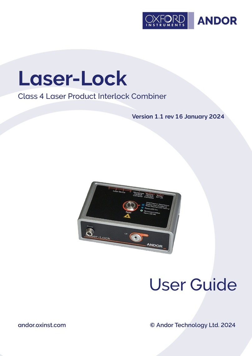
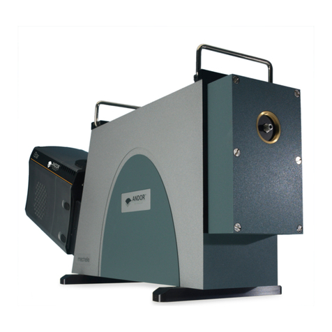
Andor Technology Dragonfly 500 Installation instructions

Dragony 500
Hardware Guide
andor.com
Version 1.5 revised 20 December 2018
© Andor Technology Ltd. 2018.

Dragony 500
2
Version 1.5 rev 20 Dec 2018
TABLE OF CONTENTS
SECTION 1: INTRODUCTION............................................................................................................. 16
1.1 TECHNICAL SUPPORT.......................................................................................................... 16
1.2 DISCLAIMER .......................................................................................................................... 17
1.3 COPYRIGHT AND PROTECTIVE NOTICES........................................................................... 17
1.4 TRADEMARKS AND PATENT INFORMATION....................................................................... 17
1.5 SUPPLIED COMPONENTS .................................................................................................... 18
1.6 OPTIONAL COMPONENTS.................................................................................................... 19
1.7 RECOMMENDED EMISSION FILTERS.................................................................................. 19
SECTION 2: PRODUCT OVERVIEW................................................................................................... 20
2.1 AN INTRODUCTION TO THE DRAGONFLY .......................................................................... 20
2.1.1 System Integration.................................................................................................... 20
2.1.2 Outline of the Functionality of Imaging Modes* ...................................................... 21
2.2 SYSTEM CONFIGURATIONS................................................................................................. 23
2.3 MICROSCOPE REQUIREMENTS .......................................................................................... 23
2.4 CAMERA ORIENTATION REQUIREMENTS ........................................................................... 23
2.5 EXTERNAL FEATURES OF THE DRAGONFLY 500............................................................... 24
2.5.1 Connections Panel and Status Display.................................................................... 25
2.5.2 Power Supply............................................................................................................ 26
2.5.3 Laser Safety Interlock System ................................................................................. 27
2.5.3.1 Interlock Summary Diagram.................................................................... 28
SECTION 3: INSTALLATION ............................................................................................................... 29
3.1 LOCATION AND MOUNTING ................................................................................................. 29
3.2 VENTILATION ......................................................................................................................... 29
3.3 ASSEMBLY ............................................................................................................................. 29
3.4 TRANSPORT AND STORAGE................................................................................................ 30

Dragony 500
3
Version 1.5 rev 20 Dec 2018
3.5 LASER CLASSIFICATION OF AN INSTALLED SYSTEM ....................................................... 30
SECTION 4: OPERATION ................................................................................................................... 32
4.1 EMERGENCY MAINS DISCONNECTION .............................................................................. 32
4.2 POWER-UP SEQUENCE........................................................................................................ 32
4.3 POWER-DOWN SEQUENCE.................................................................................................. 33
4.4 RISK MITIGATION .................................................................................................................. 33
4.4.1 Mechanical Housings ............................................................................................... 33
4.4.2 Hazards Due to Moisture or Liquids ........................................................................ 33
4.5 USING THE DRAGONFLY 500 ............................................................................................... 34
4.5.1 Stage Cover............................................................................................................... 34
4.5.2 Controlling the Dragony 500 through the Software............................................... 34
4.6 ADDITIONAL PROCEDURES................................................................................................. 35
4.6.1 Removal of the Emission Filter Wheel ..................................................................... 35
4.6.2 Insertion of the Emission Filter Wheel ..................................................................... 38
4.6.3 Replacement of Emission Filters in the Filter Wheel............................................... 39
4.6.4 Exchanging Emission Splitting Dichroics .............................................................. 40
4.6.5 Camera XY Adjustment ............................................................................................ 42
SECTION 5: MAINTENANCE.............................................................................................................. 46
5.1 CLEANING AND DECONTAMINATION .................................................................................. 46
5.2 REGULAR CHECKS ............................................................................................................... 46
5.3 ANNUAL ELECTRICAL SAFETY CHECKS ............................................................................ 46
5.4 EXTENDED WARRANTY ........................................................................................................ 46
SECTION 6: TROUBLESHOOTING .................................................................................................... 47
6.1 TROUBLESHOOTING EXAMPLES ........................................................................................ 47
6.1.1 Problem Reporting Form .......................................................................................... 52
SECTION 7: TECHNICAL SPECIFICATIONS ..................................................................................... 53
7.1 GENERAL SPECIFICATIONS ................................................................................................. 53
7.2 ENVIRONMENTAL SPECIFICATIONS.................................................................................... 53
7.3 POWER SUPPLY REQUIREMENTS....................................................................................... 53

Dragony 500
4
Version 1.5 rev 20 Dec 2018
APPENDIX A: MECHANICAL DRAWINGS ......................................................................................... 54
APPENDIX B: GLOSSARY.................................................................................................................. 55
APPENDIX C: OTHER INFORMATION............................................................................................... 56

Dragony 500
5
Version 1.5 rev 20 Dec 2018
Revision History
Version Released Description
1.0 29 Jul 2016 Initial release - intended for internal use only.
1.1 21 Jul 2017
Updated product labels.
Updated cover page design.
Added labelling locations.
Added Camera XY adjustment procedure (Section 4.6.5)
Added references to check MyAndor for further information.
Updated references to Dragony as Dragony 500. (For Dragony 200 refer to the
Dragony 200 manual).
1.2 08 Mar 2018
Further detail added to Camera XY adjustment procedure (Section 4.6.5)
Information added regarding interlock system (Section 2.5.3)
Updated Camera Zoom image (page 22)
1.3 04 Apr 2018 Claried Cylindrical lens and TIRF modules are not eld upgradeable options.
(Section 1.6)
1.4 10 May 2018 Emission lters replacement procedure is for service personnel only (Section 4.6.3)
1.5 20 Dec 2018 Updated laser safety notes for stage cover (Guidelines for Safe Operation of Laser
Products).
Updates to the ManUal
Changes are periodically made to the product and these will be incorporated into new editions of the manual. Please
check for new releases of the manual in MyAndor: http://my.andor.com/login.aspx. If you nd an issue in this manual
please contact your customer support representative (Section 1.1) with a description of the issue.

Dragony 500
6
Version 1.5 rev 20 Dec 2018
Safety and Warning Information
PLEASE READ THIS INFORMATION FIRST
WARNINGS
• USE OF CONTROLS OR ADJUSTMENTS OR PERFORMANCE OF PROCEDURES OTHER THAN THOSE
SPECIFIED HEREIN MAY RESULT IN HAZARDOUS RADIATION EXPOSURE.
• NOTE THE HAND CRUSH HAZARDS IN SECTION 4.6
1. If the equipment is used in a manner not specied by Andor, the protection provided by the equipment may be
impaired.
2. Do not position this product so that it is difcult to operate the mains disconnecting device. See SECTION 4.1,
“Emergency Mains Disconnection”.
3. Before using the system, please follow and adhere to all warnings, safety, manual handling and operating
instructions located either on the product, or this manual.
4. Keep this manual in a safe place for future reference.
5. Users must be authorised and trained personnel only; otherwise this may result in personal injury, and/ or
equipment damage and impaired system performance.
6. There are no user-serviceable parts inside the product and the enclosure must not be opened. Only authorised
service personnel may service this equipment.
7. This product will be used with lasers.
8. IEC Technical Document IEC TR 60825-14 recommends the presence of a Laser Safety Ofcer (LSO); however,
national guidelines should be referred to.
9. This equipment has not been designed and manufactured for the medical diagnosis of patients.
10. Do not attempt to bypass any safety interlocks. They are provided to comply with the safety requirements of
various regulatory agencies and must be employed to protect the operator.
11. Protective earth is an integral part of the protection against electric shock in this product, and is provided via
the earth pin of the external power supply. Ensure that this is plugged into the building earth system via the
mains socket. Do not tamper with any of the earthing measures.
12. Any AC/DC Power Supply used with this product must meet the requirements specied in Section 7.3.
13. Only use a mains cord certied to the safety regulations for your region and suitably rated for the mains supply
specied in Section 7.3.
14. Make sure the power supply cord is located so that it will not be subject to damage. If replacement of the
detachable power supply cord is required, ensure replacement is of same type and rating.
15. Locate the laser source, Dragony 500 and any other components connected via bre optic cables within 2 m
of each other so that the interconnecting bres are not stretched, bent, or constrained.
16. While running an experiment, keep room temperature as stable as possible.

Dragony 500
7
Version 1.5 rev 20 Dec 2018
17. Performance of the system may be adversely affected by rapidly changing environmental conditions or
operation outside of the operating conditions specied in SECTION 7 “TECHNICAL SPECIFICATIONS”.
18. Electromagnetic Compatibility: This is a Class A product. In a domestic environment this product may cause
electromagnetic interference, in which case the user may be required to take adequate measures.
19. This product has been designed and tested to perform successfully in a normal (basic) electromagnetic
environment, e.g. a typical life science test laboratory, as per the EU EMC Directive. It is not designed to
operate in a harsh electromagnetic environment, e.g. close to the following equipment: EMI/RFI generators,
electrostatic eld generators, electromagnetic or radioactive devices, plasma sources, arc welders, x-ray
instruments, intense pulsed sources, or other similar sources of high energy elds whose emissions are not
within the normal range expected under the EU EMC Directive.
20. The green/yellow cable (“Earth Strap”) connecting the optical breadboard to earth is necessary for this product
to protect against certain EMC disturbances and to comply with the EU EMC Directive and other international
EMC regulations. It is also a good idea to de-risk such a large piece of uninsulated metal from causing
electrocution in the event of damage to mains cables. Do not remove it.
21. Please note that this product is not designed to provide protection from ionising radiation. Any customer using
this product in such an application should provide their own protection.
22. Service must only be completed by authorised service personnel with the power turned off as internal moving
parts are not interlocked and should be considered potential pinch points.
23. This product is a precision scientic instrument containing fragile components. Always handle it with care.
24. Ensure bre cables are not bent tightly as this may damage the internal optical bre. For transport or storage,
bre cables should be coiled with a diameter of 300 mm or greater.
25. Do not wet or spill liquids on the product, and do not store or place liquids on the product.
26. If spillage occurs on the product, switch off power immediately, and wipe off with a dry, lint-free cloth.
27. If any ingress of liquids has occurred or is suspected, unplug the mains cables, do not use, and contact Andor
customer support.
28. Do not expose the product to extreme hot or cold temperatures.
29. Do not expose the product to open ames.
30. Do not allow objects to fall on the product.
31. See SECTION 5.1, “Cleaning and Decontamination”.

Dragony 500
8
Version 1.5 rev 20 Dec 2018
laser safety
WARNING – USE OF CONTROLS OR ADJUSTMENTS OR PERFORMANCE OF PROCEDURES OTHER THAN
THOSE SPECIFIED HEREIN MAY RESULT IN HAZARDOUS RADIATION EXPOSURE
This product is designed to be integrated with lasers that cover the entire visible spectrum and extend into the invisible
infra-red spectrum. This section of the manual is designed to make the end-user aware of the hazards of the product
due to these lasers. Laser safety hazards differ from those of normal light sources and users must be familiar with the
hazardous properties of lasers as these are high intensity, highly collimated beams of electromagnetic radiation.
Andor recommend that all facilities have an established system for the safe use of lasers as per their national
frameworks and Occupational Health and Safety legislation. “IEC 60285-1” and “American National Standard Z136.1-
2007- Safe use of Lasers” may be useful references for good practice.
laser prodUct classification
The Dragony 500 does not contain any embedded laser sources but it is intended to be integrated with a compatible
laser source and has therefore been designed to safely accept, and handle laser radiation. The Dragony 500 unit and all
ancillary components of the Dragony 500 system have been designed and labelled to be compliant with IEC 60825-1
and CDRH Title 21 CFR 1040.10.
When assembled and integrated in the intended manner, Dragony 500 will form part of a unique laser product
formed by the entire system. The classication of this product will depend entirely on the laser source connected and
the associated research-grade microscope. Therefore the nal system must be assessed, classied and labelled in
accordance with the requirements of IEC 60825-1 and CDRH Title 21 CFR 1040.10.
This must be performed by a competent, trained individual e.g. the site’s Laser Safety Ofcer. In such cases where
the system is installed by an Andor representative, it is Andor’s responsibility to assess and classify the nal system.
The customer support engineer will be competent and trained to perform this and ensure that the system is correctly
classied and labelled (this is shown later in this Section “Laser Classication for an installed system”).
The customer support engineer will be competent and trained to perform this and ensure that the system is correctly
classied and labelled. Please refer to Section 3.5 for guidance on the assessment and classication procedure.

Dragony 500
9
Version 1.5 rev 20 Dec 2018
laser safety and prodUct coMpliance labels
All relevant safety compliance information is visibly displayed on the product as per the International Laser Safety
Standard IEC 60825-1 and the U.S. Laser Product Performance Standard 21 CFR 1040.10.
As the Dragony 500 system will form part of a unique conguration of components, it cannot be classied in isolation.
Therefore when integrated, it may form part of a system with one of the classications described below. A label in the
format depicted below will be included for application by the system integrator following assessment and classication.
The Dragony 500 may be congured as part of a larger system that includes multiple Class 3B and Class 4 lasers. A
number of separate emission wavelengths can also be available in any one system. In some very rare occasions another
classication label may be used, this will be explained in additional documentation if this is required.
Class 3B
Laser products that are normally hazardous when intrabeam ocular exposure occurs
(i.e. within the Nominal Ocular Hazard Distance, NOHD) including accidental short time
exposure. Viewing diffuse reections is normally safe. Class 3B lasers which approach the
Accessible Emission Limits (AEL) for Class 3B may produce minor skin injuries or even
pose a risk of igniting ammable materials. However, this is only likely if the beam is a
small focused spot.
Note: There exist some theoretical (but rare) viewing conditions where viewing a diffuse
reection could exceed the Maximum Permitted Exposure (MPE). For example for Class
3B lasers having powers approaching the AEL, lengthy viewing of greater than 10 s of true
diffuse reections of visible radiation and viewing at distances less than 13 cm between
the diffusing surface and the cornea can exceed the MPE.
Class 4
Laser products for which intrabeam viewing and skin exposure is hazardous and for which
the viewing of diffuse reections may be hazardous. These lasers also often represent a
re hazard.

Dragony 500
10
Version 1.5 rev 20 Dec 2018
laser classification locations
The access panels are labelled with Laser Classication / Explanatory Labels- as described later in this section. If the
Dragony 500 is to be re-classied by a site’s trained and competent individual (e.g. the site’s Laser Safety Ofcer) then
they must ensure that labels of the correct classication and wavelength range are placed in all of the locations.
laser apertUre
The System Integrator MUST ensure that the nal system’s laser aperture is suitably labelled e.g. the microscope’s
Objective is identied by a label on the microscope’s stage top.
The appropriate aperture label(s) are included with the documentation for application by the system integrator. The
location and example labels are shown later in this section.
description of eMitted radiation froM the laser prodUct
Parameter Values Notes
Wavelengths 400-800 nm Exact outputs will depend on the integrated laser source, please refer
to it’s Explanatory Label and User Documentation
Beam Divergence 0.3-1.49 NA Exact divergence will be dependent on the objective in use, please
refer to the microscope’s User Documentation
Maximum Power or
Energy Output
<1W The maximum output power will depend on the integrated laser
source and the congured optical elements but will be signicantly
less than 1W (Class 4)
Pulse Duration N/A All recommended laser sources for the Dragony 500 are Continuous
Wave output
Pulse Repetition
Rate
N/A All recommended laser sources for the Dragony 500 are Continuous
Wave output
Irregular Pulse
Pattern
N/A All recommended laser sources for the Dragony 500 are Continuous
Wave output
description of eMitted radiation froM the integrated laser soUrce
This is dependent on the laser source integrated with the Dragony 500 system. As there are multiple options that are
available from Andor, or the Dragony 500 may be integrated with a customer’s existing laser source(s), please refer to
the laser source’s explanatory label and user documentation for a description of its emitted radiation.
recoMMended responsibilities of alaser safety officer
These include, but are not restricted to, the following; however, national guidelines should also be referred to:
1. Ensure that all personnel requiring access to the product are fully trained in both using the product and the
general use of Class 3B and Class 4 lasers (see below).
2. Ensure users are familiar with the hazardous properties of lasers; namely that laser safety hazards differ from
those of normal light/radiation sources as they are high-intensity, highly collimated beams of electromagnetic
radiation.
3. Ensure that equipment is used in a controlled area by trained end users in accordance with national guidelines.
4. Ensure end-users are familiar with the operation of the laser’s key switch control, interlocks, emission LEDs and
other safety features.
5. Ensure that all interlocks are connected and functioning correctly (see Sections, 2.5.1 and 2.5.3).
6. We recommend that a copy of IEC 60285-1 is purchased by the laser safety ofcer for reference.

Dragony 500
11
Version 1.5 rev 20 Dec 2018
gUidelines for safe operation of laser prodUcts
1. Read the safety instructions supplied with all equipment in the system.
2. Never look into a laser beam either directly, or indirectly.
3. Do not attempt to disassemble the unit housing the lasers or any part of the system. If there a problem is
suspected, please contact Andor directly (see Section1.1, “Help and Technical Support”).
4. Restrict and control access to the area(s) where laser(s) are in use to those persons who are trained in the
dangers of lasers and trained on the safety precautions to be observed when working with lasers.
5. Ensure suitable laser warning signs are prominently displayed in the area the system operates.
6. If the system is not in use turn the laser off using the key switch.
7. On a daily basis, or before every use, verify that the laser interlock circuit (Section 2.5.3) is working by
conrming that the laser emission indicator on the source turns off when either of the following are done:
• The microscope binocular eyepieces are in the open position.
• The articulated transmitted light arm on inverted microscopes is tilted back from the functional vertical position
before using the system.
• The laser safety stage cover or protective shield is opened.
8. If it is necessary to visually locate and indicate the output of invisible wavelengths, laser viewing cards for this
purpose e.g. Thorlabs NIR Detector Card VCR5 (for 700- 1400 nm) must be used along with the appropriate
laser safety goggles.
9. Additional precautions may need to be implemented as the necessary precautions will be specic to each
system installation, conguration and typical mode of use. The responsible Laser Safety Ofcer must assess
and implement the necessary precautions to avoid possible exposure to hazardous radiation during use.
eye protection
Eye protection is not required for the safe use of the device as the only radiation observable (without intentional misuse)
is directionally stable, diffuse and highly divergent from the designated aperture which is static and labelled. Eye
protection must be used by all Installation and service personnel when accessing any radiation during any installation or
service procedure.
If eye protection is deemed desirable by the local Laser Safety Ofcer, Andor recommends the following products:
• 360 nm – 510 nm – Kentek KXP-4001 Spectacles
• 510 nm – 670 nm – Kentek KRA 6702 Spectacles
• 670 nm – 800 nm – Kentek KMZ-215C Spectacles

Dragony 500
12
Version 1.5 rev 20 Dec 2018
inforMation on Viewing apertUres
In order to view any of the apertures, it is necessary to use eye protection to reduce the intensity of the laser power to
acceptable levels for viewing. The table below provides the appropriate OD values required for each wavelength.
WARNING: THE USER IS RESPONSIBLE FOR ACQUIRING THE APPROPRIATE GOGGLES TO MEET THESE SAFETY
REQUIREMENTS IF VIEWING IS REQUIRED.
It should also be noted that since the laser selection covers many wavelengths, it may not be possible to nd a single
pair of goggles to provide the necessary protection.
Wavelength (nm) Max. Laser Power (mW) Optical Density for Safe Viewing
405 180 4
445 67.5 4
458 67.5 4
473 67.5 4
488 180 4
514 36 3
515 135 3
532 90 3
552 90 3
561 135 3
594 45 3
637 126 3
640 126 3
685 126 3
730 27 3
750 360 4
785 108 3
working with optical fibres
1. Only service personnel authorized by Andor should remove or inspect bres.
2. The laser radiation passing through bres is potentially hazardous, so great care should be taken to avoid
exposure to this radiation.
3. The bre can be easily damaged by bending or general mishandling. Ensure that the minimum curvature is
never exceeded when handling. Recommended minimum bend radius is 300 mm.
4. Optical bres are prone to damage by bending local to the connector.
5. The coupler is not designed to withstand pulling of the bre. If the bre is pulled the system performance could
be compromised or the system may fail.

Dragony 500
13
Version 1.5 rev 20 Dec 2018
PRODUCT INFORMATION AND WARNING LABELLING
This section highlights the location and description of the product information and warning labels of the Dragony 500.
Product comPliance and information labels
Figure 1: Product Compliance and Information Label (Connections Panel and Standby Button labels also shown)
This label indicates the product compliance with the applicable standards. It also provides information on the
manufacturer and identies the model, serial number, and manufacturing date (month, year). A warning also highlights
that the Dragony 500 requires a multi-person lift for transport and installation (refer to Section 3).
inner door labels
Figure 2: Inner Door Labelling
This label located on the Emission Pathway Panel shows the opening instructions e.g. to access the lter wheels.
Connections
Panel Label
(see Section 2.5.1)
Standby Button
Label
(see Section 2.5.2)

Dragony 500
14
Version 1.5 rev 20 Dec 2018
Port selection mirror access labels
Figure 3: The Port Selection Mirror Access Label
This label highlights the potential Dichroic Access Door Crush Hazard and information for the installed Dichroics. Power
Off the Dragony 500 before accessing the Camera Splitter dichroic slider. Please see Section 4.6.
filter Wheel labels
Figure 4: Location of Filter Wheel Labels
Further information on the exchange of lters and dichroics is shown in Section 4.6.
Each lter wheel is labelled with information of each
lter installed (as shown in the above example)
Note the hand crush hazard warning for each lter
wheel. Do not place any limb or item into the Filter
Wheel aperture when a lter wheel is removed.
Information for each dichroic installed is
listed- as shown in the above example.

Dragony 500
15
Version 1.5 rev 20 Dec 2018
service access Panel labels
Figure 5: Panel Access Laser Warning Labels
Figure 6: Engine Access Top Panel (Service only)
laser aPerture Warning labels (microscoPe oculars and stage)
Figure 7: Microscope Laser Hazard warning labels on Oculars (left) and Stage (right)
The above label located under the Engine
Access Panel highlights the potential hand
crush hazard if the top panel is removed.
THIS PANEL MUST NOT BE REMOVED BY THE
USER.
The above label highlights the
accessible laser hazard (in
this example Laser Class 3B)
if the panels are removed.
Note: Units without TIRF module also
have warning on the blanking panel
(requires tooled removal)

Dragony 500
16
Version 1.5 rev 20 Dec 2018
INTRODUCTION
SECTION 1: INTRODUCTION
1.1
technical sUpport
If you have any questions regarding the use of this equipment, please contact the representative* from whom your
system was purchased, or:
Europe USA
Andor Technology Ltd.
7 Millennium Way
Springvale Business Park
Belfast
BT12 7AL
Northern Ireland
Tel. +44 (0) 28 9023 7126
Fax. +44 (0) 28 9031 0792
Andor Technology
425 Sullivan Avenue
Suite # 3
South Windsor
CT 06074
USA
Tel. +1 (860) 290-9211
Fax. +1 (860) 290-9566
Asia-Pacic China
Andor Technology (Japan)
IS Building
3-32-42 Higashi-Shinagawa
Shinagawa-ku,
Tokyo 140-0002
Japan
Tel: +81-3-6732-8968
Fax: +81-3-6732-8939
Andor Technology
Unit 1, Building A,
66 Zhufang Rd,
Haidian Dist.
Beijing 100085
China
Tel: +86 (0)10 8271 9066
Fax. +86(0)10 8271 9055
* The latest contact details for your local representative can be found on the contact and support page of our website.

Dragony 500
17
Version 1.5 rev 20 Dec 2018
INTRODUCTION
1.2
disclaiMer
THE INFORMATION CONTAINED HEREIN IS PROVIDED “AS IS” WITHOUT WARRANTY, CONDITION OR
REPRESENTATION OF ANY KIND, EITHER EXPRESS, IMPLIED, STATUTORY OR OTHERWISE, INCLUDING BUT NOT
LIMITED TO, ANY WARRANTY OF MERCHANTABILITY, NON-INFRINGEMENT OR FITNESS FOR A PARTICULAR
PURPOSE.
IN NO EVENT SHALL ANDOR BE LIABLE FOR ANY LOSS OR DAMAGE, WHETHER DIRECT, INDIRECT, SPECIAL,
INCIDENTAL, CONSEQUENTIAL OR OTHERWISE HOWSOEVER CAUSED WHETHER ARISING IN CONTRACT, TORT
OR OTHERWISE, ARISING OUT OF OR IN CONNECTION WITH THE USE OF THE INFORMATION PROVIDED HEREIN.
1.3
copyright and protectiVe notices
The copyright in this document and the associated drawings are the property of Andor Technology Ltd. and all rights
are reserved. This document and the associated drawings are issued on condition that they are not copied, reprinted or
reproduced, nor their contents disclosed.
The publication of information in this documentation does not imply freedom from any patent or proprietary right of
Andor Technology Ltd. or any third party.
1.4
tradeMarks and patent inforMation
Andor and the Andor logo are trademarks of Andor Technology Ltd. Andor Technology Ltd. is an Oxford Instruments
company. All other marks are property of their owners. Borealis includes technology covered by the following patents:
US Patent No. 8,275,226, EP Patent No. 2196839, US Patent No. 8,670,178 and CA Patent No. 2779146.

Dragony 500
18
Version 1.5 rev 20 Dec 2018
INTRODUCTION
1.5
sUpplied coMponents
The Dragony 500 system may be supplied in different congurations along with components and accessories required
for your specic application. Please refer to your ordering information and check the packing list to conrm that all parts
are present.
Description Quantity
Dragony 500 Unit
(note conguration and functionality depends on Dragony model ordered) 1
24 V Power Supply 1 Emission lter wheel controller 1
Power cable (country specic) 1
Microscope port adapter and
bellows (microscope specic, as
ordered)
1
User manuals in electronic format 1 USB 2.0 male-male A-B cable
(locking type) 1
PC WorkStation (as ordered) 1 Borealis Beam Conditioning Unit 1
Regional keyboard 1 Multi-mode optical bre, 2 m, 50 µm 1
Software (as ordered e.g. Fusion) - Single-mode optical bre
(as ordered for TIRF) 1
Filter Wheel, 8 position, 25 mm (inc.
cover plates and 1” lter blanks) 2* Interlock kit 1
Male-male null-modem DB-9 RS-
232 serial cable (supplied with lter
wheel controller)
1Metric (M6) and imperial (1/4”-20)
feet locking screws
3 of
each
type
FW-1000 female-female DB-9 drive
cables (supplied with lter wheels) 2Microscope raising pedestal kit
(microscope specic, as ordered) 1
Notes: Filters as specied at time of ordering.

Dragony 500
19
Version 1.5 rev 20 Dec 2018
INTRODUCTION
1.6
optional coMponents
There are a range of optional components available for the Dragony 500 including:
1. Multi-band excitation dichroic optics for multiplexing excitation laser light (up to 3 optics, motorized
selection, installed by service/support engineer only).
2. Camera Port Selection/Image Splitting dichroic Broadband mirror/window for 100% throughput camera port
selection or dichroic mirrors for simultaneous emission splitting (up to 4 lters per cassette, motorized selection
and user exchangeable).
3. Emission lters (8 per wheel, motorized selection and user exchangeable).
4. Additional motorized emission lter wheels (user exchangeable).
5. Cylindrical lens for 3D super-resolution localization microscopy or particle tracking applications (must be
specied at time of order, not eld-upgradeable).
6. Imaris Software for advanced image analysis and visualisation capabilities.
7. TIRF Module can be tted to upgrade models without TIRF (must be specied at time of order, not eld-
upgradeable).
Notes:
• Andor provide a range of other microscopy system components that can be congured with or alongside
Dragony 500. Please contact your nearest Andor Sales representative for further information on these other
system accessories.
• Use only accessories supplied and recommended by Andor (except for the AC/DC Power Supply, which must
meet the specication of Section 7.3, and mains cables, which must be certied for the country of use).
1.7
recoMMended eMission filters
For the latest information on available emission lter options please visit the Dragony page on andor.com.
Please contact your nearest Andor Sales representative for further information on these and other system components
available.

Dragony 500
PRODUCT OVERVIEW
20
Version 1.5 rev 20 Dec 2018
SECTION 2: PRODUCT OVERVIEW
This section provides an overview of the main features of the Dragony 500.
2.1
anintrodUction to the dragonfly
The Dragony 500 is a multi-modal imaging platform enabling laser-based wideeld, spinning-disk confocal,
and optionally Total Internal Reectance Fluorescence (TIRF) microscopy when connected to a research-grade
microscope. This product is intended for professional scientic research applications, especially live-cell biological
imaging and photo-stimulation.
Figure 8: The Dragony 500- shown with Andor iXon Ultra EMCCD and Zyla sCMOS Cameras
2.1.1
systeM integration
The Dragony 500 is shown as part of an integrated system in the diagram of Figure 9. Laser light from an Integrated
Laser Engine (ILE) is fed as an input into one port of the Dragony 500 via a multi-mode optical bre for wideeld and
confocal illumination (passing rst through a Borealis Beam Conditioning Unit – BCU) and/or a single-mode optical
bre through a different port for TIRF illumination.
Figure 9: A Simple Representation of a Dragony 500 System (with ILE, BCU and Cameras)
Single-mode bre
BCU Output
TIRF Input
Camera
Camera
BCUILE Dragony 500
Microscope
Wideeld/
Confocal
Input
Multi-mode
bre
1
2
Filter Wheel Controller
Table of contents
Other Andor Technology Laboratory Equipment manuals