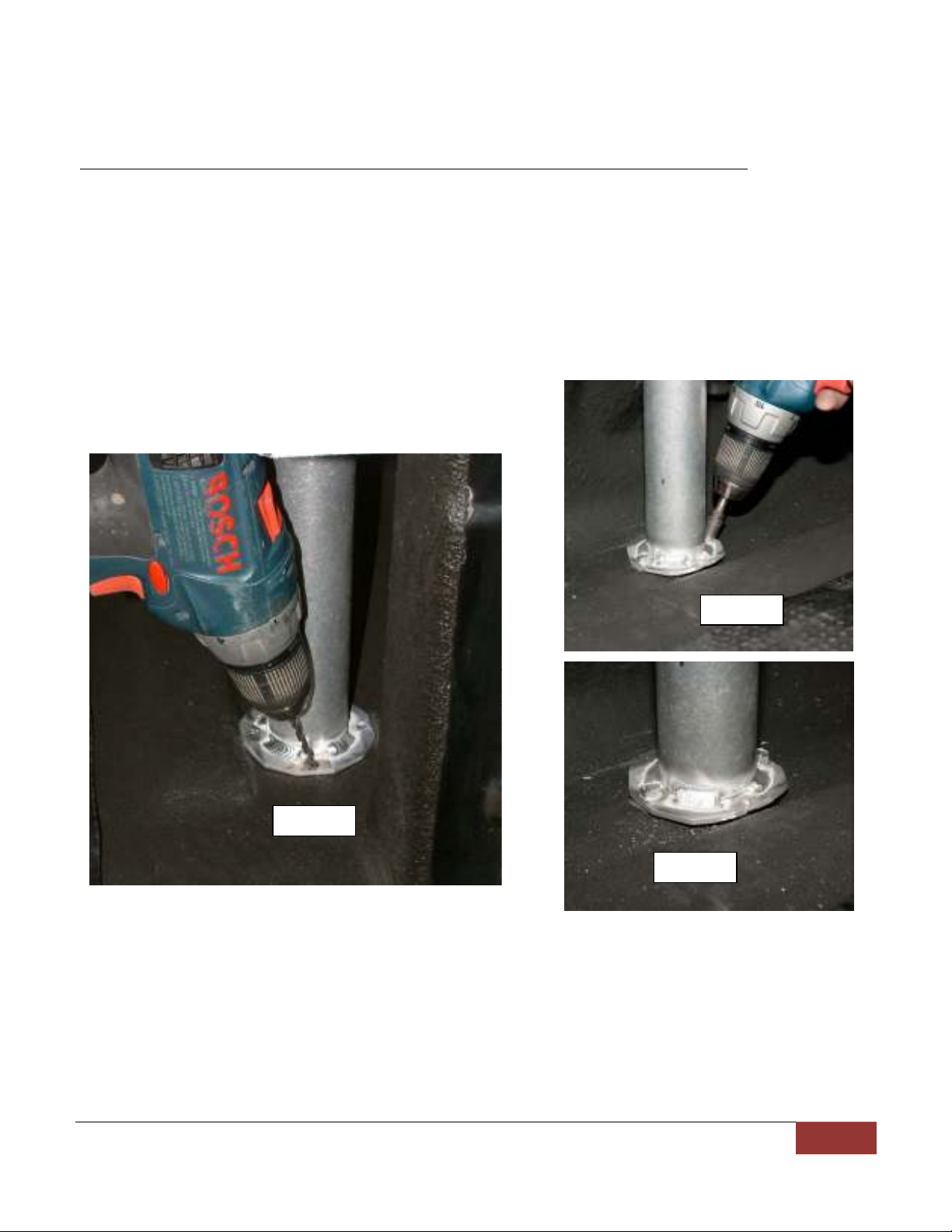
AndyMark TEKTRAY Setup guide

AndyMark, Inc.
TekTray
-
700 E. Firmi
n St., Kokomo, IN 46902
765
)
868
-
0932
1
Installation,
Usage Tips,
&
Warranty Information

AndyMark, Inc.
TekTray
-
700 E. Firmi
n St., Kokomo, IN 46902
765
)
868
-
0932
2
Table of Contents
1. Bill of Materials page 2
2. Tools Needed page 3
3. Installation: Steps 1 through 10 pages 3-12
4. Usage Tips, Technical Assistance, Warnings page 13
5. Warranty page 14
Bill of Materials
ITEM COMPONENT QUANTITY
1 ASSEMBLED TRAY
Includes: handles, linkage, slide bearings, lock pins
1
2 LEFT RAIL 1
3 RIGHT RAIL 1
4 LEFT RISER 2
5 RIGHT RISER 2
6 CROSS TUBE 1
7 CROSS TUBE INSERT with FOOT 2
8 END-OF-TRAVEL STOP
Rubber cylinder, 5/16-18x1” BHCS w/ Lock Nut & Washer
4
9 CROSS TUBE FOOT SPACER 2
10 LARGE RUBBER WASHER 1+7/8” diameter x 1/8” thick) 8
11 5/16-18 x 2.25 inch FHCS Flat Head Cap Screw) 2
12 5/16-18 NYLOCK NUT 2
13 1/4-20 x 1.5 inch FHCS Flat Head Cap Screw) 2
14 1/4-20 COLLAPSIBLE NUT Gray and bronze color) 2
15 1/4-20 x 1 inch SHCS Socket Head Cap Screw) 8
16 1/4-20 NYLOCK NUT 8
17 1/4-20 x 3/4 inch SELF-TAPPING SCREW 8

AndyMark, Inc.
TekTray
-
700 E. Firmi
n St., Kokomo, IN 46902
765
)
868
-
0932
3
Tools Needed
1. Power Drill
2. Drill Bits metal drilling): 3/16” & 7/16” diameter
3. Tape Measure
4. Allen Wrenches: 3/16” & 5/32”
5. Socket Drivers: 3/8”, 7/16”, and 1/2”
6. Open-ended Wrench: 1/4”
7. Metal marking Punch
8. Small Carpenter’s Square
9. A 10 ft. x 10 ft. cleared flat surface is recommended for rail assembly.
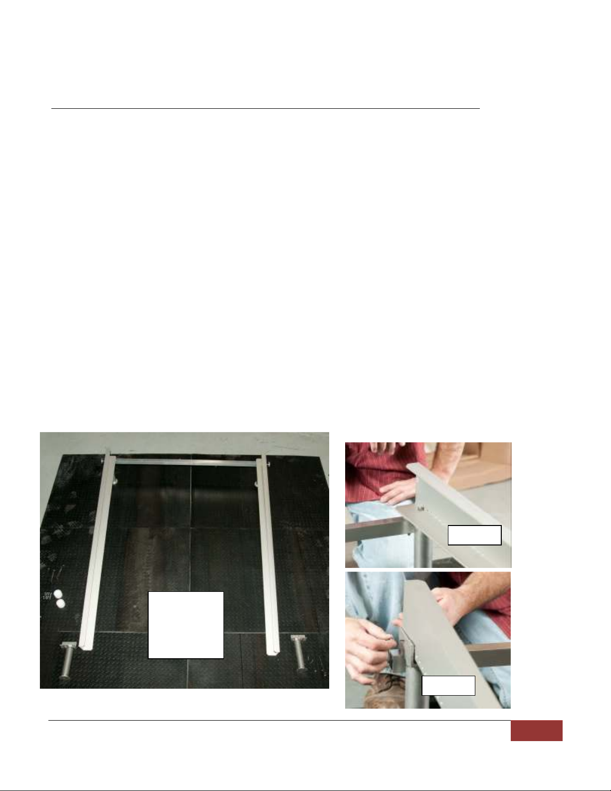
Step 1 Preliminary Items and Suggestions
1.1. Ensure all parts are included in your TekTray packages one long box, one large
flat box) as listed on the Bill of Materials.
1.2. Inspect all items for shipping damage
1.3. Remove all material, debris and miscellaneous items from truck bed
1.4. TekTray does not install easily for trucks with drop-in liners. Remove the liner
or call technical assistance for more detailed instructions 765-868-4779).
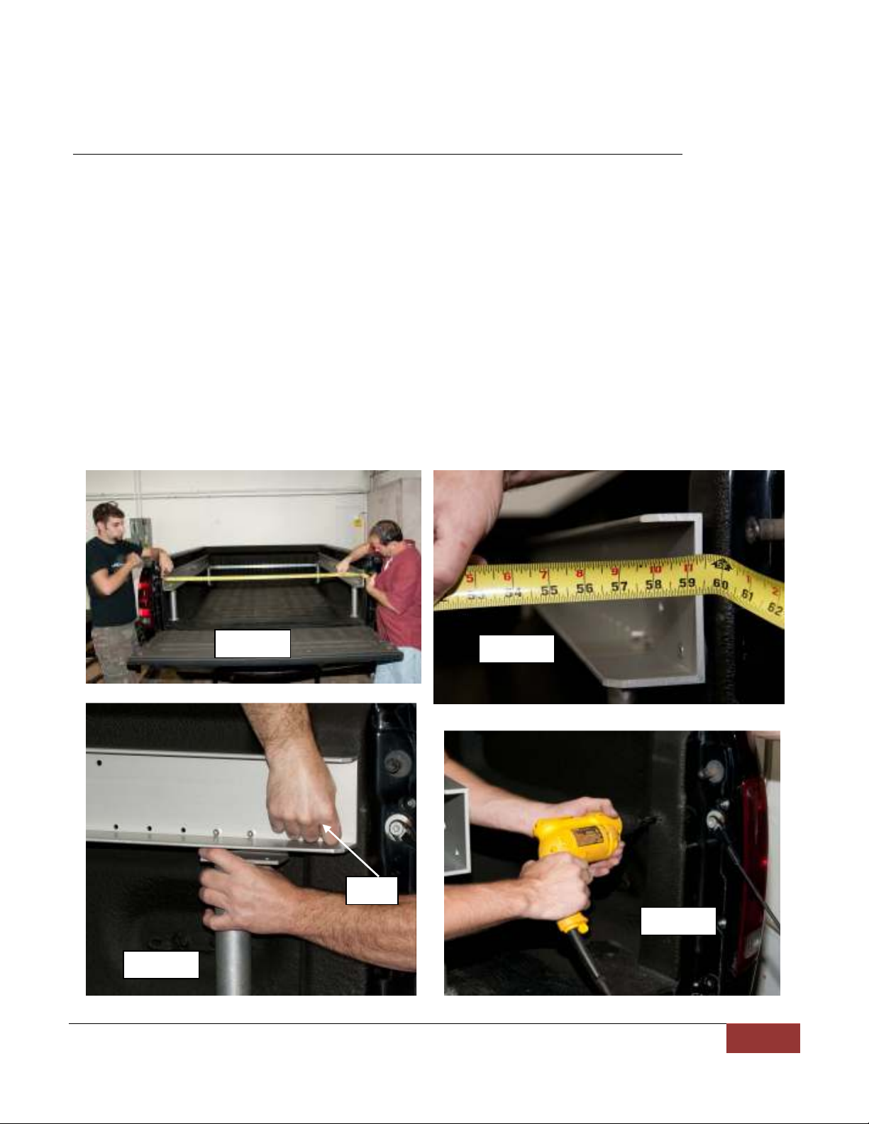
1.5. During installation, before drilling ANY holes, be sure the rail layout is correct.

AndyMark, Inc.
TekTray
-
700 E. Firmi
n St., Kokomo, IN 46902
765
)
868
-
0932
4
Step 2 Front RISER / CROSS TUBE Assembly
2.1 Slide the CROSS TUBE INSERT with FOOT item 7) into each end of the CROSS TUBE
item 6) so that the through holes align.
2.2 Position CROSS TUBE below bracket of LEFT RISER item 4) and RIGHT RISER item 5).
2.3 Align countersunk hole in RISER bracket, CROSS TUBE hole and CROSS TUBE INSERT
with FOOT 7), and insert the 5/16 – 18 x 2.25 inch FHCS item 11) into hole and
thread on the 5/16-18 NYLOCK NUT item 12).
2.4 Repeat for both ends of CROSS TUBE 6).
2.5 Tighten the 5/16 screws to nuts so the RISERS are at right angles to the CROSS TUBE
6).
2.6 This assembled portion of rail structure is now called RISER/CROSS TUBE.
Step 2.1
Step 2.1
Align these
holes
Step 2.2
Step 2.3
Step 2.6

AndyMark, Inc.
TekTray
-
700 E. Firmi
n St., Kokomo, IN 46902
765
)
868
-
0932
5
Step 3 Attach RISER/CROSS TUBE to LEFT RAIL and RIGHT RAIL
3.1 Place RISER/CROSS TUBE assembly in front end of truck bed near cab) to see how
this assembly will fit with bed features. RISER/CROSS TUBE assembly can be
oriented such that CROSS TUBE 6) is on either side of RISER by rotating
RISER/CROSS TUBE 180 degrees.
3.2 Remove RISER/CROSS TUBE from truck bed, and lay the RISER/CROSS TUBE
perpendicular to the RAILs. Be sure the RISER/CROSS TUBE is positioned on the
end of the RAILS with the row of small holes that are 1 inch apart.
3.3 Lift front of RIGHT RAIL and align one hole on RISER/CROSS TUBE with one hole
on RIGHT RAIL. Insert 1/4-20 x 1 inch SHCS item 15) and fasten 1/4-20 NYLOCK
NUT 16) only “finger tight”. Choosing the correct hole during step 3.3 and 3.4
will determine how far the RAILs will protrude past the RISER/CROSS TUBE.
Various hole mounting locations may need to be tried to find the best fit in the
truck bed.
3.4 Repeat step 3.3 for LEFT RAIL using the same corresponding holes.
Step 3.3
Step 3.2
RISER/CROSS
TUBE & RAIL
LAYOUT
Step 3.4

AndyMark, Inc.
TekTray
-
700 E. Firmi
n St., Kokomo, IN 46902
765
)
868
-
0932
6
Step 4 Install Rear LEFT RISER and Rear RIGHT RISER
4.1 Install LEFT RISER and RIGHT RISER on rear end of RAILs.
4.2 Align RAILs on RISERS and install two 2) 1/4-20 x 1 inch SHCS item 15) per side.
Use 1/4-20 NYLOCK NUTS item 16) to secure and tighten bolts.
Step 5 Finish Fastening Front LEFT RISER and RIGHT RISER
5.1 Complete the fastening of the RAILs to front RISERs by inserting 1/4-20 x 1 inch SHCS
15) through aligned holes. Two screws attach each RISER to the RAILs. Use 1/4-20
NYLOCK NUT 16) to secure and tighten bolts in place.
STATUS CHECK: Each RISER is fastened to a RAIL with two (2) 1/4 20 x 1 inch SHCS (two
per RISER). The RISER, CROSS TUBE, RAIL ASSEMBLY (aka: RAIL ASSEMBLY) is complete.
Step 4.1
Step 4.2

AndyMark, Inc.
TekTray
-
700 E. Firmi
n St., Kokomo, IN 46902
765
)
868
-
0932
7
Step 6 Install RAIL ASSEMBLY into truck bed
6.1 Carefully set the RAIL ASSEMBLY into the truck bed, positioning the CROSS TUBE 6)
to the front of the truck bed nearest to the cab).
6.2 Align LEFT 2) and RIGHT RAIL 3) ends even with the back edge of the rear vertical
bed posts.
6.3 Push the RAIL ASSEMBLY toward front of bed, creating a 1/4 to 1/2 inch gap from
the RAIL end to where the face of the tailgate will be when closed.
6.4 The FOOT on each end of the CROSS TUBE 6) is screwed out to push on a solid part
of the truck bed side wall. Measure edge of RAIL to inside of bed at the same
location on both sides) & adjust FEET so distance is equal on both sides. For wide
truck beds, the plastic CROSS TUBE FOOT SPACER 9) should be used. Extend each
FOOT tightly against the truck bed side wall.
6.5 Close the tail gate, ensuring clearance between RAIL end and tail gate face.
Step 6.1
Step 6.4
Step 6.2

AndyMark, Inc.
TekTray
-
700 E. Firmi
n St., Kokomo, IN 46902
765
)
868
-
0932
8
Step 7 Front RAIL Spacing Adjustment and Fastening
7.1 The measurement of the outside face of the LEFT RAIL 2) to outside face of the
RIGHT RAIL 3) should equal 59.5” +/- 1/16”.
7.2 The gap between the outside of each RAIL and the truck bed post should be equal
from side to side, ranging from 1/8” to 1/2”. For each 1/8” of this gap, one LARGE
RUBBER WASHER 1+7/8” dia., item 11) will be used as a spacer in step 7.6.
7.3 Make sure rear RISERs are vertical, using small carpenter square. Mark a hole on
the truck bed post, through the 1/4 inch diameter hole on the LEFT RAIL 2) and
RIGHT RAIL 3). This hole is the furthest rear hole in the RAIL.
7.4 Slide the RIGHT RAIL 3) toward the interior of the truck bed
7.5 Using the 7/16” drill bit, drill through the left truck bed post where marked in 7.3.
Step 7.1
Step 7.1
Step 7.3
Step 7.5
Hole

AndyMark, Inc.
TekTray
-
700 E. Firmi
n St., Kokomo, IN 46902
765
)
868
-
0932
9
7.6 Insert 1/4-20 x 1.5 inch FHCS item 13) into left RAIL countersunk hole, adding the
correct number of LARGE RUBBER WASHERs 10) on the outside of the RAIL
determined in step 7.2.
7.7 Insert the 1/4-20 COLLAPSIBLE NUT item 14) onto the end of the 1/4-20 x 1.5 FHCS
13), screwing the NUT onto the screw.
7.8 Push the 1/4-20 COLLAPSIBLE NUT 14) into the 7/16” hole.
7.9 Tighten the 1/4-20 x 1.5 FHCS 13) until the LARGE RUBBER WASHERs 10) and the
1/4-20 COLLAPSIBLE NUT 14) is tight between the RAIL and the truck bed post.
7.10 Repeat steps 7.4 – 7.9, for mounting the LEFT RAIL to the right truck bed post.
STATUS CHECK: Both RAILs are fastened to back truck bed posts. The front ends of each
RAIL not to be fastened to the truck bed sides. Verify the outside to outside RAIL
dimension is 59.5” after RAIL fasteners have been installed.
Steps
7.6, 7.7
Step 7.8
Step 7.9
Steps
7.6, 7.7

AndyMark, Inc.
TekTray
-
700 E. Firmi
n St., Kokomo, IN 46902
765
)
868
-
0932
10
Step 8 Fasten RISER Feet to Bed Floor
8.1 Inspect all four 4) RISERs so that they are vertical and in proper location, using a
small carpeter’s square.
8.2 Choose two 2) holes at each RISER foot location for fastening holes, drilling a 3/16”
diameter pilot through the bed floor at those two 2) locations for each RISER foot.
8.3 Insert two 2) 1/4-20 x ¾ inch SELF-TAPPING SCREWs item 17) into the drilled holes
for each foot. Tighten screws with 3/8” Socket Driver.
STATUS CHECK: RISERS are vertical and not angled with respect to the truck bed floor.
RISER feet are all fastened to truck bed floor, by means of 2 screws each.
TIP: The RISER foot plate can be bent to form to the ribs in the truck bed.
Step 8
.1
Step 8.3
Step 8.3

AndyMark, Inc.
TekTray
-
700 E. Firmi
n St., Kokomo, IN 46902
765
)
868
-
0932
11
Step 9 Install the TRAY
9.1 This is a two 2) person task.
9.2 Lift the ASSEMBLED TRAY and align the bearing groove located on the bottom of
the TRAY, on either side) to fit into the bottom portion of the LEFT and RIGHT RAIL,
inserting the TRAY with handles facing out.
9.3 Push the TRAY forward, turning the lock handles clockwise, drawing the lock pins
inward, allowing the TRAY to move completely into the bed on the RAILS.
9.4 Release lock handles, allowing the spring-loaded lock pins to insert into the rear set
of lock holes, located on the RAILS.
9.5 Inspect both lock pins, confirming the pins fully penetrate through the RAIL lock
holes. The lock pins should protrude through the back side of the RAIL holes on both
sides. If not, check steps 2-8 and re-position RAILS for proper spacing and height.
9.6 Lock the TRAY in the front postion, and inspect the lock pin insertion as in step 9.5.
STATUS CHECK: ASSEMBLED TRAY should glide freely on RAILs, moving with 5 7 pounds
of push force. Ensure TRAY easily locks with both pins in front and rear locking positions.
Step 9.1
Step 9.2
Step 9.3

AndyMark, Inc.
TekTray
-
700 E. Firmi
n St., Kokomo, IN 46902
765
)
868
-
0932
12
Step 10 Install the END-OF-TRAVEL STOPS
10.1 Push TRAY completely forward, toward the truck cab.
10.2 Locate one 1) 5/16” diameter hole in RIGHT RAIL 3) approximately 15 inches from
the back end of the RAIL.
10.3 Install the END-OF-TRAVEL STOP item 8) through the inside face of the rail, with
the nut being on the outside of the RAIL. Secure and tighten.
10.4 Repeat for LEFT RAIL.
10.5 Pull out TRAY, until END-OF-TRAVEL STOPs 8) limit the travel.
10.6 Locate one 1) 5/16” diameter hole in LEFT RAIL 2) approximately 41.5 inches from
the front end of the RAIL.
10.7 Install the END-OF-TRAVEL STOP 8) into this hole, just as done in step 10.3
10.8 Repeat for RIGHT RAIL 3)
STATUS CHECK: END OF TRAVEL STOPS will now limit Tray from being removed from
RAILS and from hitting the front bed wall. TekTray is fully installed.
Step 10.6
Step 10.2

AndyMark, Inc.
TekTray
-
700 E. Firmi
n St., Kokomo, IN 46902
765
)
868
-
0932
13
Usage Tips
• To extend bearing life and performance, clean RAIL sliding surface periodically.
• If mud, sand, or other debris get into bearing areas, wash out with water and
remove any debris.
Technical Assistance
• For replacement parts or technical assistance, call AndyMark, Inc. at 765)868-
4779 or email [email protected].
• For new information, please check the www.tektray.com website.
Warnings
• Lower tailgate before unlocking tray
• Lock tray before moving vehicle
• Do not unlock tray on incline
• Maximum load 750 pounds
• Never move a vehicle without making sure the TRAY is locked in front or rear
position.
The TekTray concept and design is protected by U.S. Patent # 7111887

AndyMark, Inc.
TekTray
-
700 E. Firmi
n St., Kokomo, IN 46902
765
)
868
-
0932
14
TekTray Limited 3 Year Warranty
AndyMark, Inc. guarantees that this product is free from defect in workmanship and materials from
three years of the date of the purchase of product. AndyMark, Inc will not be responsible for any
defect which has resulted from normal wear, misuse, lack of maintenance, or alteration made or
specifically authorized by anyone other than authorized service centers or installation centers.
Product must be registered for this warranty to have effect. The product must be returned to origin of
purchase with proof of purchase and explanation of return. If inspection of the parts verifies a defect in
workmanship and/or materials the product will be repaired or replaced at our election. If product
cannot be quickly replaced and/or repaired we may refund the purchase to the buyer.
Please fill out the Warranty Registration Card below and send to this address:
AndyMark, Inc.
700 E. Firmin St. #114
Kokomo, IN 46902
TekTray Warranty Registration Card
First Name: Last Name:
Address: City: State: Zip:
Email: Phone Number:
Vehicle Make: Year: Vehicle Model:
Indicate Type of Use Circle) : Commercial Personal
Purchasing Location: City: State:
or if by Internet Order: Order #
TekTray Serial Number: Purchase Date:
Comments:
Table of contents
Popular Automobile Accessories manuals by other brands

Clifford
Clifford Garage Door Receiver Premier owner's guide

Lippert Components
Lippert Components A-Frame Coupler Installation and owner's manual

SIERRA OFFROAD
SIERRA OFFROAD 10-40-YJS Installation guidelines

ZENEC
ZENEC ZE-RVC85WA Mounting instructions

Seecode
Seecode 232519 instruction manual

Vortex
Vortex 2011-2012 MUSTANG GT installation instructions

Acewell
Acewell ACE-64 Series user manual

Datalink Systems
Datalink Systems maestro Rr manual

Metra Electronics
Metra Electronics 99-8204 installation instructions

SEC
SEC 06929 installation instructions

PureFlow AirDog
PureFlow AirDog DF-100-5G installation instructions

Faller
Faller Car System Digital Quick installation guide