ANEP BOX TX+ User manual

ANEP BOX TX+
REMOTE ELEVATOR ALARM OPERATION CONTROL
SCALABLE MULTI-LIFT INTERCOM AND VOICE SYSTEMSCALABLE MULTI-LIFT INTERCOM AND VOICE SYSTEM
NT_ANEP_BOX_TX+_EN_04-07-2023

2
NT_ANEP_BOX_TX+_EN_04-07-2023
1 - RECOMMANDATIONS
This documentation is aimed at professionals who are trained and experienced in
the lift industry.
1.1 - Installation / Commissioning
Consequently, when working on an elevator to install ANEP equipment, safety
rules specic to the profession must be respected.
● Use of «Personal Protective Equipment».
● Switch off the system before making any electrical connections.
● Make yourself safe before working in a shaft.
Before handling anep equipment, make sure it is DE-ENERGIZED.
On all «ANEP BOX» equipment (TA, TA+, TX, TX+, ...)
It is essential to connect all peripherals BEFORE connecting
the telephone line :
- Cabin alarm button (NO or NC dry contact)
- Cabin faceplate (MIDIS) or speaker and microphone (BA-mini-GHP)
- Under-cab audio (BOX-SC)
- ANEP ALIM CONTROL-II type 230 / 12V battery-backed and controlled
power supply (if auditory magnetic loop and/or Yellow/Green LEDs)
1.2 - Pendant cable
We recommend that you fit the elevator with a shielded pendant cable to ensure
excellent voice quality and avoid any disturbances that could lead to malfunctions.
Particular care must be taken to ensure that the telephone line is routed in such a
way as not to degrade standard technical characteristics..
Check the wiring, especially if it connects multiple elevator machines.
● Type of cable, Cable routing (low/high current), Parasites (VMC,
generators), etc ...
Electrical equipment must be recycled in accordance with
Directive n°2012/19/EU of 7/04/2012 on waste electrical and
electronic equipment (WEEE).

3
NT_ANEP_BOX_TX+_EN_04-07-2023
SUMMARY
1 - RECOMMANDATIONS Page 2
1.1 - Installation / Commissioning
1.2 - Pendant cable
2 - GENERAL Page 6
2.1 - Technical data
3 - BOX-TX+ CONNECTION Page 7
3.1 - Sensor connection Page 8
3.2 -Position sensor connection and alignment Page 9
3.2.1 - Elevator with short floor Page 10
3.3 - PO and PF sensor connection Page 11
3.3.1 - Single-access elevator
3.3.2 - Dual-access elevator
3.4 - Programming for special cases Page 12
3.4.1 - Elevator with fully manual doors
3.4.2 - Elevator with mixed doors (swing and automatic)
4 - CONNECTING YELLOW & GREEN LEDS (If MIDIS absent) Page 13
4.1 - Yellow & Green LED programming / EN81-28 2003 or 2018 standards Page 14
5 - CABIN ALARM DISCRIMINATION Page 15
5.1 - Discrimination not validated
5.2 - Discrimination interne
5.3 - External Discrimination BOX-DISCRI
5.4 - Forced alarm
6 - ADDRESS / TRANSMITTER NUMBER PROGRAMMING Page16
6.1 - Addressing Module number :
7 - PROGRAMMING Page18
7.1 - Access to programming
7.2 - Exit programming mode
7.3 - Choice of telephone network Page 19
7.3.1 - Standard mode
7.3.2 - Autocom mode Page 20
7.3.3 - GSM mode
7.4 - Number programming Page 21
7.4.1 - Number programming
Ex: Programming memory 101
7.4.2 - Programming a memory with a pause (autocom)
7.4.3 - Delete a number

4
NT_ANEP_BOX_TX+_EN_04-07-2023
7.5 - Memory allocation Page 22
7.5.1 - Transfer method
7.5.2 - Table for single-communication programming.
7.5.3 - Dual call «mode conguration»
7.6 - Validations and parameter settings Page 23
7.6.1 - Alarm button delay time
7.7 - Blocked person call acknowledgement (EN81-28) by #1
7.8 - Communication time Page 24
7.9 - Cabin phone sound level adjustment
7.10 - Periodic call validation (or cyclic test) Page 25
7.11 - Test cyclique / Périodicité
7.11.1 - Call management Cyclic test Page 26
7.12 - Intercom mode gain settings for machinery and firefighters Page 27
7.13 - Listening to data exchange
7.14 - Programming access code modification
7.15 - Cabin light control timer Page 28
7.15.1 - Cabin light input management
7.16 - Management of extensions on DISCRI input Page 30
7.17 - BOX-ENVOIS extension management Page 32
8 - OPERATIONS Page 33
8.1 - Cabin alarm test
8.2 - Cabin roof technician alarm Page 34
8.3 - Automatic on-hook (phone mode)
8.5 - Green button functions Page 35
9 - BOX TX+ FUNCTIONS Page 36
9.1 - Voice synthesis on blocked user alarm
9.2 - Alarm siren
9.2.1 - Alarm siren on alarm button

5
NT_ANEP_BOX_TX+_EN_04-07-2023
9.3 - BOX TX+ clock setting Page 37
9.3.2 - Local time display
9.4 - Floor statement
9.4.1 - Statement validation Page 38
9.4.2 - Devalidation of statements
9.4.3 - Level programming via keypad
Modification of floor announcements Page 39
9.4.4 - Broadcasting between 8 a.m. and 8 p.m. Page 40
9.4.5 - Indication de la période d’annonce des étages
10 - SERVICE VOICE / ALARM ACKNOWLEDGEMENT Page 40
10.1 - Validation of «Alarm in Progress» & «Technician Arrival» announcements
10.2 - Disabling of «Alarm in progress» & «Technician arrival» announcements
10.3 - Cabin alarm acknowledgement
11 - SPEAKER AND MICROPHONE TEST Page 41
11.1 - Periodic call test
11.2 - Test on request operator
12 - PRESENTATION OF THE TX+ VERSION Page 42
12.1 - Elevator monitoring Page 43
12.1.1 - Validation of elevator monitoring mode
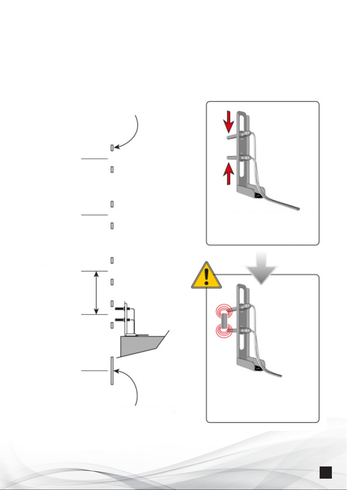
12.1.2 - Learning procedure
12.1.3 - Sheath learning launch Page 44
12.2 - Event validation (Faults/Malfunctions)
12.2.1 - Event validation sequence
Sheath learning diagram Page 45
12.2.2 - Fault inhibition sequence Page 46
12.2.3 - Event references
12.2.4 – Reading fault validation Page 47
12.2.5 – Door type reading
12.2.6 – Programming inactivity time
12.2.7 – Technical fault ltering Page 48
12.3 - Commissioning checks Page 49
12.3.1 - Door information control
12.3.2 - Monitoring control
12.3.2.1 - Check surveillance mode validation
12.3.2.2 - Check synthesizer operation
12.3.2.3 - Checking failure transfer
13 - KEYBOARD PROGRAMMING TABLE Page 50
KEYBOARD PROGRAMMING TABLE (CONTINUED) Page 51
14 - KEYBOARD PROGRAMMING TABLE WITH BOX-INTENS Page 52
NOTES AND WARRANTY Page 53

6
NT_ANEP_BOX_TX+_EN_04-07-2023
2 - GENERAL
2.1 - Technical data
• Complies with European standards EN81-28 (2003 and 2018) and EN81-70*.
• Integrated or remote voice modules
• Triphonic function by adding BOX-SC or BOX-C modules
• Cabin roof mounting
• Remote-powered via analog telephone line or powered if the magnetic loop or green/
yellow LEDs are connected
• Multifrequency dialing mode
• Automatic off-hook
• Volume and acoustics control (locally or remotely)
• Location recognition
• Send call location identification to ANEPCenter® or anepanywhere.com website
• 12-key programming keypad
• 1 input from cabin alarm button (NO or NC)
• 1 button with two functions: blocked person alarm acknowledgement, technician
arrival and departure.
• 1 cab roof technician alarm button
• 6 telephone number memories
• Automatic redial of second number in case of busy or no answer
• Battery and maintenance free EEprom memories
• Cyclic test (1, 2 or 3 days)
• Remote programming possible with ANEPCenter®
• Synthesis circuit for floor announcements and voice messages
• 1 «Cabin light» input
• Elevator operation control (remote monitoring)
Factory settings
• Programming code : Ý123
• Communication time : 3 minutes
• Hung up : Automatic
• Cyclic test : 3 days
* Standard EN81-28 Remote alarm for new elevators since October 2003 and 2018
Standard EN 81-70 Safety rules for the construction and installation of elevators Part
70: Accessibility to elevators for all persons including persons with disabilities.

7
NT_ANEP_BOX_TX+_EN_04-07-2023
3 - BOX TX+ CONNECTION (configuration example)
BOX-DISCRI
BOX-SECU
BOX-INTENS
OR
OR
BOX-TX+
*,1,2,3
ALIM-CONTROL II
(ref ANEP A-BA-039)
MAGNETIC
SENSOR
HIGH
MAGNETIC
SENSOR
LOW
RJ11
To Y/G LEDS
(Cables supplied
with ANEP phony)
TELEPHONE LINE
230Vac
green
white
brown
Phony
CABIN
(MIDIS BP)
PB
CABIN
ALARM
(NO ou NC)
Under-cabin
telephony
(BOX-SC)
OD
CD
OD
CD
MSH
MSL
... or
⁎ MIDIS-FACEPLATE
⁎ LIGAN / LIGAN-BP
⁎ MICRO-DEP.
⁎ BA-MAX
⁎ BA-mini-GHP
MSH
MSL
SECTOR
230Vac
TEST

8
NT_ANEP_BOX_TX+_EN_04-07-2023
3.1 - SENSOR CONNECTION
Car door open/close and elevator travel information are connected to ANEP BOX
inputs E1 to E4.
These inputs are provided with dry, E1 - Cabin door OPEN
potential-free contacts.. E2 - Cabin door CLOSED
E3 - Magnetic sensor HIGH
E4 - Magnetic sensor LOW
Note: These 4 items of information are compulsory for the statements to work..
BOX-TX+
*
,1,2,3
MAGNETIC
SENSOR
HIGH
MAGNETIC
SENSOR
LOW OD
E1
E2
E3
E4
MSHMSL
CD
OD
OPEN
DOORS
CD
CLOSED
DOORS
DMH
DMB

9
NT_ANEP_BOX_TX+_EN_04-07-2023
3.2 - CONNECTION OF POSITION / OFFSET SENSORS [E3] AND [E4].
UMPTEENTH
LEVEL
4th LEVEL
3rd LEVEL
2nd LEVEL
1st LEVEL
(*) NOTE : The resetting magnet is to be placed at
the level where the cab passes most often
(Example: Ground floor for an R+4)
If there is an ad lag in operation,
we need to increase the distance
between magnets, or increase the distance
magnetic sensor.
Counting magnets
Height = 50 mm
Resetting magnet *
Height = 200 mm
UPPER MAGNET
COUNTING MAGNETS
LOWER MAGNET
50mm
50mm
RESETTING MAGNET
200mm
Y
Y
≤10mm
MAX
15° MAX
SETUP
MAGNETIC
SENSOR
HIGH
MAGNETIC
SENSOR
LOW
MSH
MSL

10
NT_ANEP_BOX_TX+_EN_04-07-2023
3.2.1 - Elevator with short oors
The minimum value for detecting short oors is 700mm between two oors (oor
information).
ELEVATION ELEVATOR SHAFT (example)
COUNTING MAGNETS
2nd floor
1st floor
Ground floor
High
Ground floor
Low
UNDERGROUND
RESETTING MAGNET
Decrease sensors spacing
allows reconciliation
counting magnets
A counting magnet must
not be able to operate
2 sensors at the same time
(Detection of a readjustment)
CABIN

11
NT_ANEP_BOX_TX+_EN_04-07-2023
3.3 - PO* and PF** sensor connection [E3] and [E4].
* DO = Door Open ** DC = Door Closed
3.3.1 - Single-access elevator.
Door information
DO/DC is connected
to inputs E1 (DO) and
E2 (DC).
3.3.2 - Dual-access
elevator.
DO/DC door
information must
be doubled. (DO
in parallel and DC
in series)
NOTE: PF IS THE
GONG STARTER
IF THE SYNTHESIS STARTS WHEN THE ELEVATOR STOPS BEFORE THE
DOOR IS OPENED, A PF SENSOR IS INCORRECTLY SET.
DOOR 2
DOOR 1
DOOR 1 DOOR 2
CD (2)CD (1)
DO (1)
DO (2)
DO DO
DOOR DOOR
CD
OD
OD CD

12
NT_ANEP_BOX_TX+_EN_04-07-2023
3.4 Programming for special cases
3.4.1 - Elevator with fully manual doors
The «Inactivity» time delay value must be greater than that for an elevator with
automatic doors. (Manual door closing). All door faults must be deprogrammed,
as door opening and closing depends on the user.
3.4.2 - Elevator with mixed doors (swing and automatic)
Programming: swing doors (even if only one swing door).
De-programming: start-up fault (elevator is parked in automatic doors).
If the lower end is an automatic door, start learning (alarm button) with the door
open, then let it close after registering the upper command.
3.4.3 - Factory settings
The BOX TX+ module is delivered with a set of parameters csalled «Factory Settings».
PARAMETERS FACTORY CONFIGURATION
Programming code
*
123
Communication time 3 minutes
Hung up Automatic
Periodic call frequency 3 days
Transmitter number Factory serial number (8 digits, see label on box)
Module number 1
Telephone numbers Not programmed (empty memories)
Telephone network Analog telephone line (PSTN / RTC)
Cabin alarm Bt delay 1 second
Bt cabin alarm delay with BOX-DISCRI 25,3 seconds
Operator acquittal Not validated
Yellow/Green indicator management Standard 2003
Cabin light entry times 0 minutes
Discrimination Cabin alarm Not validated
Loudspeaker activated during data
transmission Not validated
Speech synthesis for oor statements Activated
Voice synthesis for service messages * Activated
Remote monitoring functions Not validated
(*) Service messages :
Technician Arrival and Departure
Alarm in progress

13
NT_ANEP_BOX_TX+_EN_04-07-2023
4 - YELLOW & GREEN LED CONNECTION (if MIDIS absent)
- Connect indicator lights used in the cab in accordance with standards NF EN
81.28 of 2003 or 2018 and 81.70 (12Vdc / 140 mA max per light)
(see Page 14).
- Connect a 12Vdc power supply (from 9 to 15Vdc) type ALIM CONTROL-II.
No such connection is required when using MIDIS phonics.
Common cathode indicators
COMMON
CATHODES
YELLOW
LIGHT
GREEN
LIGHT
SECTOR
220Vac
Common LEDs

14
NT_ANEP_BOX_TX+_EN_04-07-2023
4.1 - Yellow & Green LEDs can be programmed according to EN81-28 2003 or
2018 standards
In programming mode Ý123
Depending on the type of standard required for indicator management,
successively press the #417#, or #418#, or #419#
EN81-
282003
STANDARD
OFF OFF Standby / NORMAL MODE
#417#
ON ÞÞOFF Alarm activated, call in progress
OFF ON ÞÞIn communication with a call center
operator
OFF OFF Communication ended, line hung up, Alarm
acknowledged (remote or on-site)
EN81-
282018
STANDARD
OFF OFF Standby / NORMAL MODE
#418#
ON ÞÞOFF Alarm activated, call in progress
ON ÞÞON ÞÞIn communication with a call center
operator
ON ÞÞOFF Call ended, line hung up
OFF OFF Acknowledged alarm (remote or on-site)
FLASHES
ÞÞºÞÞºFLASHES
ºÞÞºÞÞProgrammed cyclic test fault
EN81-
282018
STANDARD
YELLOW
OFF
OFF OFF Standby / NORMAL MODE
#419#
ON ÞÞOFF Alarm activated, call in progress
ON ÞÞON ÞÞIn communication with a call center
operator
OFF OFF Call ended, line hung up
OFF OFF Acknowledged alarm (remote or on-site)
FLASHES
ÞÞºÞÞºFLASHES
ºÞÞºÞÞProgrammed cyclic test fault
Programming on ANEP BOX keypad
After activating the programming access mode Ý123
#417# Validates management of Yellow and Green LEDs to 2003 standards
#418# Validates the management of Yellow and Green lights to 2018 standards
#419# Validates management of yellow and green LEDs to 2018 stan-
dards, with yellow LED off after communication (end of alarm).

15
NT_ANEP_BOX_TX+_EN_04-07-2023
5 - CABIN ALARM DISCRIMINATION
• Alarm discrimination is used to prevent untimely, unfounded alarms being
transmitted as a result of incorrect use or malicious intent.
• Discrimination can be carried out either internally or externally, or not validated
When a technician is present, discrimination is not carried out.
5.1 - Discrimination not validated
This configuration mode enables the cabin alarm to be taken into account
permanently.
In programming mode Ý123 (see Page 18)
Successively press the #307#
ANEP BOX TX+ beeps 3 times
5.2 - Internal discrimination
In this mode, ANEP BOX TX+ processes the opening and closing of car
and landing doors, as well as the movement of the elevator.
Inputs E1, E2 receive the DO, DC contacts of the cabin door.
The alarm is discriminated :
• When the elevator moves.
• For the rst 15 seconds after the elevator has stopped at the oor.
• When both cabin and landing doors are open.
In programming mode Ý123 (voir Page 18)
Successively press the #308#
ANEP BOX TX+ beeps 3 times
5.3 - External discrimination BOX-DISCRI / DISCRI input extension
See page 31
5.4 - Forced alarm
When discrimination is enabled, the cabin alarm can still be triggered if the
cabin button is pressed 4 times within 15 minutes. Each time the button is
pressed, it must be held for longer than the programmed acknowledgement
time, and the button must be released for at least 3 seconds between each
press.

16
NT_ANEP_BOX_TX+_EN_04-07-2023
6 - ADDRESSING AND PROGRAMMING THE TRANSMITTER NUMBER
Programming the transmitter number (or Identier or PROM) :
The ANEP BOX module identies itself in data mode by sending its
«Transmitter number» (also called Identier or PROM depending on the call
center).
This number corresponds to the serial number of the ANEP BOX module.
This transmitter number can be modied to adapt to the different databases of
the receiving centers.
Note: The transmitter number is numeric and has 8 digits.
Ex : 5 2 2 1 1 5 6 9
ATTENTION: changing the transmitter number does not require
prior access to programming.
Ý#22220 xx xx xx xx #Ý
xx xx xx xx = 8-digit transmitter number
6.1 - Addressing Module number :
Multiple ANEP BOX modules can be installed on the same telephone line
(up to a maximum of 8), but each module’s address must be configured.
In programming mode :
#303 then 1 # if module 1(Elevator 1)
or
#303 then 2 # if module 2(Elevator 2)
or
#303 then 8 # if module 8(Elevator 8)
Note : Module = ANEP BOX TX (or TX+)
or ANEP BOX-C (pit bottom)
BOX-C

17
NT_ANEP_BOX_TX+_EN_04-07-2023
Configuration 1 - Remote pit telephony with BOX-C
Addressing on 4 BOX TX+ and 4 BOX-C
Configuration 2 - Embedded hardware with BOX-SC (8 maximum)
Addressing to be carried out on the 8 BOX TX+ units
NOTE: These quantities are to be divided by 2 when using a GSM gateway.
=> 4x BOX TX+ with BOX-SC (under cab)
=> 2x BOX TX+ with BOX-C (pit bottom)
TELEPHONE LINE
Module 1
BOX TX+
BOX C
Module 1
Module 2
BOX TX+
BOX C
Module 2
Module 3
BOX TX+
BOX C
Module 3
Module 4
BOX TX+
BOX C
Module 4
LIFT 1 LIFT 2 LIFT 3 LIFT 4
TELEPHONE LINE
Module 1
BOX TX+
BOX SC
Module 1
LIFT 1
Module 2
BOX TX+
BOX SC
Module 2
LIFT 2
Module 3
BOX TX+
BOX SC
Module 3
LIFT 3
Module 4
BOX TX+
BOX SC
Module 4
LIFT 4
Module 5
BOX TX+
BOX SC
Module 5
LIFT 5
Module 6
BOX TX+
BOX SC
Module 6
LIFT 6
Module 7
BOX TX+
BOX SC
Module 7
LIFT 7
Module 8
BOX TX+
BOX SC
Module 8
LIFT 8

18
NT_ANEP_BOX_TX+_EN_04-07-2023
7 - PROGRAMMATION (ANEP BOX hung up)
Important :
• All ANEP BOX TX+ devices connected to the same telephone line must be
connected to enable access to programming mode.
• Programming is performed using the ANEP BOX TX+ keypad.
• To prevent unwanted manipulation, access to ANEP BOX TX+ programming is
protected by a three-digit access code:
Ý123
• This code can be modified by the user (1 to 7 digits) (See page 27)
7.1 - Access to programming
Type
*
followed by the digits of the programming access code
Example: (With factory default code)
à
*
123 The device emits a melody
The device is now in programming mode.
... 2 « beeps » every 20 seconds
7.2 - Exit programming mode
When you have finished programming the device
àPress the « Ý»
End of programming, the device emits a melody
Note: If no key is pressed for 3 minutes, the device exits programming mode.
The device emits a melody

19
NT_ANEP_BOX_TX+_EN_04-07-2023
7.3 - Choice of telephone network
The BOX TX+ module uses a telephone network to transfer alarms to a reception
center. To ensure correct operation of the equipment, it is important to indicate
the type of network between :
- Switched telephone network (analog PSTN),
- GSM Gateway,
- Autocom mode.
The choice of network affects the following functions :
- GSM Gateway battery charge information (PG1,PGU, P3GU and P4GU
models only)
- Loudspeaker and microphone phonics control,
- Secure data transfer to a reception center
Autocom mode allows BOX TX+ to operate with most autocoms, but does not
guarantee operation with ALL autocoms on the market.
This mode allows:
- Numbering with quiescent line voltages between 20 and 28v,
- Off-hook if ringing time exceeds 400ms
7.3.1 - Standard mode
If the voltage of your Orange or other telephone line is higher than 28V,
you must congure your equipment in «Standard mode» (Orange line) and
Normal line voltage (Line voltage > 28V).
This is the mode in which your equipment was delivered (factory mode).
To ensure this, perform the following programming sequence.
à In programming mode Ý123
Press the #404#
The device emits a melody
Exit programming mode by pressing the « Ý»,
The device emits a melody

20
NT_ANEP_BOX_TX+_EN_04-07-2023
7.3.2 - Autocom mode and/or low line voltage
If your equipment is connected to an Orange (or other operator) line, but the
line voltage at rest is low (less than 28V), you must congure your equipment
in «Autocom Mode and/or Low Line Voltage» (20V <= Line Voltage < 28V ).
Pour cela, effectuer la séquence de programmation suivante
à In programming mode Ý123
Press the #403#
The device emits a melody
Exit programming mode by pressing the Ý
The device emits a melody
7.3.3 - GSM Mode
If your equipment is connected to a GSM gateway, you must congure your
equipment in «GSM mode».
Validation du mode «GSM»
à In programming mode Ý123
Press the #405#
The device emits a melody
Exit programming mode by pressing the Ý
The device emits a melody
Disable «GSM» mode / return to Standard mode,
à In programming mode Ý123
Press the #406#
The device emits a melody
Exit programming mode by pressing the Ý
The device emits a melody
This manual suits for next models
1
Table of contents