ANETS AS SERIES INSTALLATION & OPERATIONAL MANUAL
8 150-000002 Rev A (2/19)
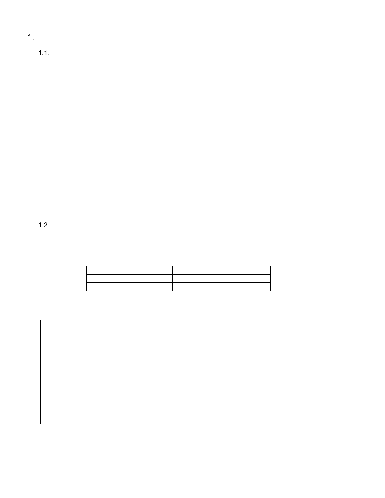
CE GAS TABLE
Refer to the following table for gas specifications for the country of use. If the country of use is NOT listed, refer
to the information printed on the data plate.
Belgium – Natural gas units require a restrictor orifice on the supply line for proper operation.
AT, BG, CH, CZ, DK, EE, FI, GB, GR, HR, HU, IE, IT, LT, LV,
NO, PL, PT, RO, ES, SI, SK, SE, TR
I
2H
LU
I
2E
FR
I
2ESI
BE
I
2E+
NO
DE
I
2ELL
NL
G25-G25.3 I
2L
- I
2EK
25 2.60 mm 2.9/2.8
BE, BG, CH, CZ, DE, ES, FR, GB, GR, HR, HU, IE, IS, IT, LT,
LU, LV, MK, MT, NL, PL, PT, RO, SI,
LP G31 I
3P
23.9 37/50 37 .0625" LP16 YES 1.0
AT, BG, CH, CZ, DK, EE, FI, GB, GR, HR, HU, IE, IT, LT, LV,
NO, PL, PT, RO, ES, SI, SK, SE, TR
I
2H
LU
I
2E
FR
I
2ESI
BE
I
2E+
NO
DE
I
2ELL
#42 / #37
NL
G25-G25.3 I
2L
- I
2EK
25 #37 3.5/3.4
BE, BG, CH, CZ, DE, ES, FR, GB, GR, HR, HU, IE, IS, IT, LT,
LU, LV, MK, MT, NL, PL, PT, RO, SI,
LP G31 I
3P
28.9 37/50 25.4 1.50 mm LP16 YES 1.2
AT, BG, CH, CZ, DK, EE, FI, GB, GR, HR, HU, IE, IT, LT, LV,
NO, PL, PT, RO, ES, SI, SK, SE, TR
I
2H
LU
I
2E
FR
I
2ESI
BE
I
2E+
NO
DE
I
2ELL
NL
G25-G25.3 I
2L
- I
2EK
25 2.70 mm (#36) 4.0/3.9
BE, BG, CH, CZ, DE, ES, FR, GB, GR, HR, HU, IE, IS, IT, LT,
LU, LV, MK, MT, NL, PL, PT, RO, SI,
LP G31 I
3P
32.9 37/50 25.4 1.59 mm (.0625") LP16 YES 1.3
AT, BG, CH, CZ, DK, EE, FI, GB, GR, HR, HU, IE, IT, LT, LV,
NO, PL, PT, RO, ES, SI, SK, SE, TR
I
2H
LU
I
2E
FR
I
2ESI
BE
I
2E+
NO
DE
I
2ELL
NL
G25-G25.3 I
2L
- I
2EK
25 2.60 mm 4.4/4.3
BE, BG, CH, CZ, DE, ES, FR, GB, GR, HR, HU, IE, IS, IT, LT,
LU, LV, MK, MT, NL, PL, PT, RO, SI,
LP G31 I
3P
36.8 37/50 25.4 1.51 mm (#53) LP16 YES 1.5
10.8
YES
20/25 #38 / #36
31.4
20
20/25
32.2 10
YES
Pilot
Orifice (code)
YES
2.44 mm N22
N22
YES
YES
YES
G20/G25
G20
45AS 35.8
Applicable
Countries
20
20/25
Nominal Gas
Rate (m3/hr)
Model
Fuel Type
Net
Input (kW)
Supply
Pressure (mbar)
Burner
Pressure (mbar)
Burner
Orifice
70AS
35AS
40AS
Nat
Nat
Nat
Nat
Gas
Appliance
Category
Gross
Input (kW)
YES
2.58 mm
(#38)
20
28.3 10 N22
G20
G20/G25 26 23.4
N22
Governor
#42 3.0
3.0/3.5
2.5/2.9
2.5
3.4
3.4/4.0
3.8/4.4
3.8
G20/G25
G20
2.38 mm
2.38 / 2.60 mm
G20
G20/G25
YES
40 20/25
20
36.0 10
Natural 7" W.C. (17.4) 4" W.C. (10) #39 N22
Propane 11" W.C. (27.4) 10 W.C. (25) .0625" LP16
Natural 7" W.C. (17.4) 4" W.C. (10) #42 N22
Propane 11" W.C. (27.4) 10 W.C. (25) 1.5 mm LP16
Natural 7" W.C. (17.4) 4" W.C. (10) #38 N22
Propane 11" W.C. (27.4) 10 W.C. (25) #52 LP16
Natural 7" W.C. (17.4) 4" W.C. (10) #39 N22
Propane 11" W.C. (27.4) 10 W.C. (25) .0625" LP16
Natural 84 Mj/h 1.74 kPa 1.0 kPa 2.53 mm (#39) 0.56 mm (N22)
ULPG 86 Mj/h 2.74 kPa 2.5 kPa 1.59 mm (.0625") 0.41 mm (LP16)
Natural 102 Mj/h 1.74 kPa 1.0 kPa 2.37 mm (#42) 0.56 mm (N22)
ULPG 104 Mj/h 2.74 kPa 2.5 kPa 1.50 mm 0.41 mm (LP16)
Natural 116 Mj/h 1.74 kPa 1.0 kPa 2.58 mm (#38) 0.56 mm (N22)
ULPG 118 Mj/h 2.74 kPa 2.5 kPa 1.61 mm (#52) 0.41 mm (LP16)
Natural 130 Mj/h 1.74 kPa 1.0 kPa 2.38 mm (#42) 0.56 mm (N22)
ULPG 133 Mj/h 2.74 kPa 2.5 kPa 1.51 mm (#53) 0.41 mm (LP16)
70AS
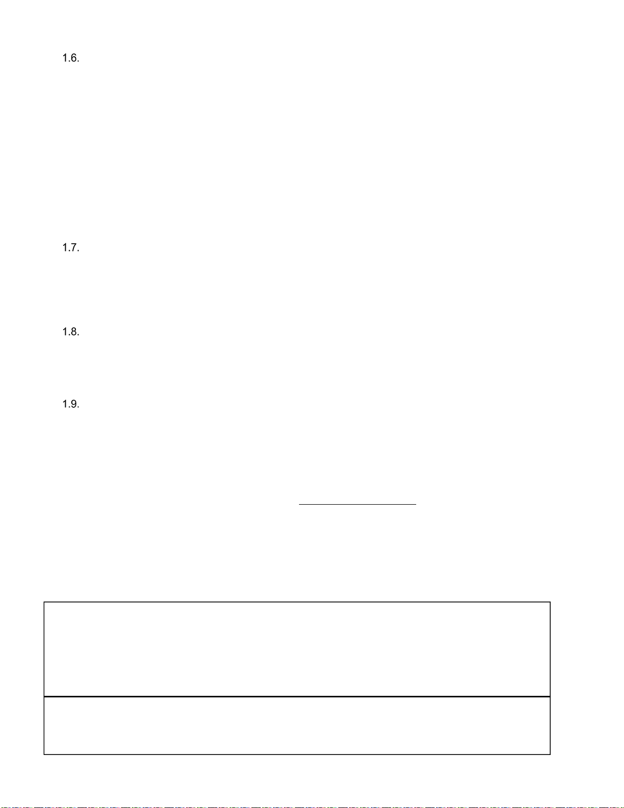
NON CE
GAS TABLE
AUSTRALIAN
GAS TABLE
144 Mj/h
129 Mj/h
95 Mj/h
107,000 (31.3)
150,000 (44)
23.7
28.2
32.2
39.6
122,000 (35.8)
45AS
40AS
45AS
70AS
35AS
40AS 113 Mj/h
Burner
Pressure
(mbar)
Burner
Orifice
Pilot
Orifice
(code)
35AS
Model
Fuel Type
Gross
Input BTUs
(kW)
Net
Input BTUs
(kW)
Supply
Pressure
(mbar)
90,000 (26.3)