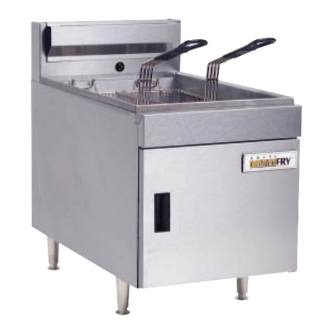
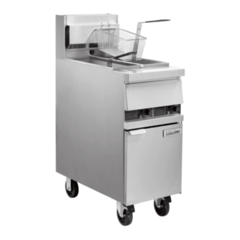
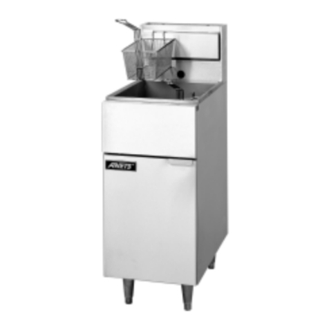
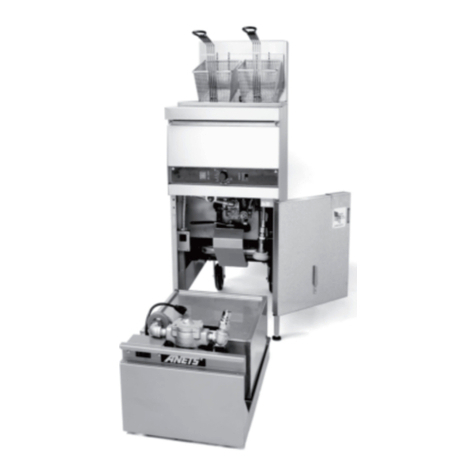
Anetsberger Brothers 14G Installation guide

1
Anetsberger Brothers, Inc.
180 North Anets Drive • Northbrook, Illinois 60062 • 847-272-0770 • Fax 847-272-1943
For ANETS Factory Warranty Service • 800-837-2638
Installation,
User Operation,
&
Maintenance
Manual
Keep this Manual in a Convenient Location for Reference
WARNING
After installation of this equipment, immediately contact your local gas
supplier to obtain information about what action to take whenever any
person smells gas. Post this information in a prominent location.
FOR YOUR SAFETY
DONOTstoreorusegasolineorotherflammablevapors
or liquids inthevicinityofthisoranyotherappliance.
DANGER
Improperinstallation,adjustment,alteration,service,ormaintenancecan
cause property damage, injury or death. Read the installation, operating
andmaintenanceinstructionsthoroughlybeforeinstallingor servicing this
equipment.
The Anets Golden Line
Quality Equipment For The Restaurant, Supermarket, and Bakery Industries
!
!
!
Form I-102 ;
Rev. 10/01
Price: $20.00 US
Models
14G, 14GS
14GU, 14GSU,
MX-14EG,MX-14EGU
FRYER
14GSshown onstandard 6” legs

2
CONTENTS
ShippingContainerInspection ........................................................ 3
FryerGasSupplySpecifications..................................................... 4
FryerElectricalSpecifications ....................................................... 4
Figure1- FryerModel 14GSWiring Diagram ....................... 4
CodeRequirements ...................................................................... 5
Figure2- FryerSiteInstallation Requirements ....................... 6
InstallationRequirements............................................................... 6
InstallationInstructions .................................................................. 7
LegInstallationInstructions ..................................................... 7
LegLevelingInstructions......................................................... 7
Figure3-Typical LegInstallation ......................................... 7
CasterInstallationInstructions ................................................. 8
Figure4- Typical Caster Installation ..................................... 8
CasterLevelingInstructions .................................................... 8
FryerRestrainingDeviceInstallationInstructions....................... 9
GasConnectionInstructions........................................................ 10
FryerOperatingInstructions........................................................ 11
FryerPreparationFor Use(“BoilOut” Instructions) .............. 12
Figure5- DrainingThe Kettle ............................................. 12
LightingProcedure................................................................ 13
Figure6-Gas Safety Valve& Control KnobPositions ........ 13
ShutdownProcedure ............................................................ 14
FoodProductFrying TimeChart............................................ 15
DailyCleaningProcedure....................................................... 16
MonthlyMaintenanceInstructions .......................................... 17
FryerTroubleshootingGuide .................................................18 - 22
FryerWarranty ............................................................................ 23
DANGER
Read these specifications, Code Requirements, Installation Requirements, Instal-
lation Instructions, and Operating Instructions very carefully. Failure to follow the
Instructions could cause the fryer to malfunction. A fryer malfunction can result in
property damage, serious bodily injury, or death.
!

3
1. Carefullyexaminetheshippingcartonfor
externaldamage. Whendamage isnoted,notify
thedeliverycarrier immediately. Saveallpacking
materialsfor damageclaimexamination.
2. If noexternal damageisnoted, removethe
shippingcartonfromthefryerand examinethe
SHIPPING CONTAINER INSPECTION
fryer carefullyfordamage. Place thefryer ina
safelocation,if damageisnoted,sothat thefreight
damageclaimsadjustercanexamine thefryer.
3. Savetheshippingcontainerforuseduring leg/
casterinstallation. Refertothe InstallationInstruc-
tionsfor thatprocedure.
Standard Accessories furnished in the shipping carton for this fryer include:
2Fryer Baskets 1DrainValveExtension 1 Screen
4AdjustableLegs 1 Cleanout Rod 1Basket Hanger
Otheroptionalequipment includesa sedimenttray;single ortriple baskets;abuilt-in Filtronic™IIorFilter
Mateunder-fryer filtersystem; afryer cover;a draintable; afront draintray; orfour casters.
Model Features
14G Plain Steel FryerKettle
14GS Stainless Steel Fryer Kettle
Plain Steel Fryer Kettle, CE version
Stainless Steel Fryer Kettle, CE version
Model Features
MX-14EG HighEfficiency Fryer
MX-14EGU HighEfficiencyFryer, CEversion
Note: A Parts List for each Anets fryer is among th eitems shipped with each fryer. If an
additional copy of this list is needed please contact the factory as directed on the back
cover.
14GU
Models Covered By This Manual
14GSU

4
Figure 1. Fryer Model 14GS Wiring Diagram
Figure1isa wiringdiagramofan
ANETS 14GS Fryer. Some fryers
mayhave otheroptions thatdo not
appearinthisbasicwiringdiagram. A
model-specificwiringdiagram included
witheachfryer showsalltheactualparts
andtheirassociatedwiringconnections.
Inaddition,a fryerequipped withabuilt-
infiltersys-tem(Filtronic IIorFilter
Mate)hasasupplementarymanual
includedforthatoption.
FRYER ELECTRICAL SPECIFICATIONS
The ANETS Fryer Models 14GS, 14GSU, MX-14EG, and MX-14EGU require no exter-
nal electric power source.
FRYER GAS SUPPLY SPECIFICATIONS
Please make sure that your desired fryer lo ation has gas
supply fa tors that are suitable for this produ t:
NaturalGas Propane
3½“W.C.** 10“W.C.
6“W.C.,minimum 11“W.C., minimum
INPUT REQUIRED:
SUPPLY PRESSURE***
MANIFOLDPRESSURE
111,000BTU*
BTU/Hr Rating is based on sea level operation. For sites above 2000 feet, reduce this
rating 4% for each 1000 feet above sea level.
“ W.C.=Inches,WaterColumn.
Measure Supply Pressure when all other gas-powered equipment is operating.
*-
***-
** -
GasSupply Inlet Pipe size mustbe¾“ NPT
(NationalPipe Thread)standard gasline. The gas
supplyinletlineshould beasstraightas possible
(fewestbends orelbows) toobtain thehighest
availablegas pressureat thefryer. Locatethis
inletlinehorizontallyatthecenter ofthedesired
fryerlocation,8¼“ abovethefloor.
NOTE: Usingaflexibleinletlinepermitsvariation
inthegassupplylinelocation,bothhorizontallyand
vertically.
Anetsfryers areonly foruse withthe typeofgas
specifiedon thespec plate. ifa fryerrequires
modificationtouse agasotherthan thatwhichis
identifiedonthe fryerspecplate, contactyou Anets
representativeor call (800) 837-2638.

5
IMPORTANT: Read the Code Requirements
and ALL installation instructions carefully,
before starting the installation. Contact the
factory if any problems or questions arise.
Thefryerinstallationmustconformwith local
codes,or in theabsence of local codes,with the
NationalFuel Gas Code, ANSIZ223.1 (latest
edition);theNaturalGasInstallation Code,CAN/
CGA-B149.1(latest edition); or the PropaneGas
InstallationCode, CAN/CGA-B149.2(latest
edition),asapplicable,including:
a. Disconnectthefryeranditsindividualshutoff
valvefromthegassupplypipingsystemduring
anypressuretesting ofthe gassupplysystem at
testpressures in excess of ½ psig(3.45 kPa).
b. Isolatethefryerfromthegassupplypiping
systemduringanypressure testingofthegas
supplysystem attestpressures equalto or
lessthan ½ psig (3.45 kPa).
c. For fryersutilizingfloorcasters,thefryerinstal-
lationshallcompriseaconnector thatcomplies
withthe Standardfor Connectors forMov-
ableGas Appliances, ANSIZ21.69 (latest
edition)or CAN/CGA6.16 (latestedition),
andaquick-disconnect devicethatcomplies
withtheStandard forQuick-Disconnect
Devicesfor Use withGas Fuel, ANSIZ21.41
orCAN/CGA 1-6.9 (latest edition).
d. Restrict themovement ofacaster-equipped
fryerbyusingalimitingdevice(forexample,a
cableattached bothtothe fryerandtoa fixture
attachedto the sitestructure) to avoiddepend-
ingonthe connectorand thequick-disconnect
deviceoritsassociatedpipingtolimitfryer
movement.
e. Install thisfryeronanon-combustiblefloor
withits backand sidesatleast6”away from
anycombustiblewall,as showninFigure2.
WARNING
Install this fryer under a ventilation
hood that conducts combustion pro-
ducts outside the building. Venting
must comply with ANSI/NFPA 96
(latest edition).
f. Install thisfryerina locationwhereadequate
combustionandventilationairisavailable.
Keepthe areadirectly infront ofthe fryer open
foradequate air flow to theburners. DO
NOTobstruct theflow ofcombustion and
ventilationair.
g. Keepthe fryerarea free andclear from
combustiblesanddebris.
h. Attacharestraining deviceto eachfryer,to
preventtheunitfromtipping,whichcould
causesplashingofhotliquid.
CODE REQUIREMENTS
!
6
Installthefryerin accordancewiththepreceding
CodeRequirements,aswellas thefollowing
InstallationRequirements.
1. DO NOTinstallthis fryerinamobile home,
trailer,orrecreationalvehicle.
2. Install thisfryerin alocationthatallows ittobe
movedawayfrom otheradjacent appliances
forcleaningandmaintenance.
NOTE: Ifthefryer isinstalledamong
arow ofappliances (“banked”)where
itsonlyconvenientmovementisfor-
ward,sufficientroommustbeavail-
ableinfront topermitits separation
fromadjacentappliancesforcleaning
andmaintenance.
3. Tightlyfasten thelegs (orcasters) tothe bot-
INSTALLATION REQUIREMENTS
tomofthe fryerusing thesuppliedhardware, to
preventthefryerfromtipping,wobblingor
rockingwhenit isinits desiredlocation. Refer
tothefollowingInstallationInstructionsforleg
orcasterattachmentandlevelinginformation.
4. Confirmthattheairfromtheventilationhood
flowingnearthefryerafterinstallationisNOT
blowingon therear ofthefryer, toprevent
affectingtheburnerflamesandpossiblycausing
controldamage.
!
CAUTION: Hood make-up air
MUSTNOT flow in a mannerthat
restrictsorimpedesthenatural flow
ofcombustionorventilationair.
Figure 2. Fryer Site Installation Requirements
From the top of the flue on
the fryer, allow a minimum
of at least 10 inches verti-
cal clearance beneath a
ventilating hood.

7
Figure 3. Typi al Leg Installation
INSTALLATION INSTRUCTIONS
7. Tightenthefourlockingnutsevenlyand
securelytoholdthelegmountingplateagainst
thefryermountingbracket.
LEG INSTALLATION
INSTRUCTIONS (Continued)
LEG LEVELING INSTRUCTIONS
1. Move thefryer toits desiredlocation.
WARNING
The fryer MUST NOT tip, rock or wob-
ble,toavoid splashing or spillingitsHOT
frying fat contents during operation.
!
2. Turnthe screw-typeleg adjustmentends as
necessarytolevelthefryer,untilnotipping,
rocking,orwobblingisevident.
3. Perform the “FryerRestrainingDevice
InstallationInstructions.”
LEG INSTALLATION
INSTRUCTIONS
1. Flattentheshippingcarton(afterunpackingthe
fryerand itsparts andaccessories)for surface
protectionduringleginstallation.
2. Position theside ofthefryerflaton thecarton,
exposingthefryerbottommountingbrackets
forleginstallation,asshownin Figure3.
3. Placethelegmountingplateflushagainstthe
mountingbracketon thefryerbottom.
4. Insertonemountingboltthroughaflat
washerand thenthrough theproper
holeinthefryermountingbracket
andthroughthelegmountingplate.
5. Screw alockingnut severalturns
ontothemountingbolt.
6. Repeat steps4 and5 untilall four
mountingboltsforalegarein place
withlockingnuts.

8
CASTER LEVELING INSTRUC-
TIONS
1. Move thefryer toits desiredlocation.
2. Determine whetherthefryer tendsto wobble
orrock whenin its desiredlocation. Ifit does
not,perform step 10, then proceed tothe
FryerOperating Instructions. If itdoes,
performsteps 3through 9.
WARNING
The fryer MUST NOT tip, rock or wob-
ble,toavoid splashing or spillingitsHOT
shortening contents during operation.
3. Determinewhichcasterrequiresadjustment
andtheapproximateamount ofchange
requiredtolevelthefryer.
4. Position therear sideof thefryer on theship-
pingcarton,exposing thebottomof thefryer
withthecastermounting plates(Figure4).
!
INSTALLATION INSTRUCTIONS (Continued)
CASTER INSTALLATION
INSTRUCTIONS
1. Flattentheshippingcarton
(afterunpackingthefryerand
itsparts and accessories)for
surfaceprotectionduringleg
installation.
2. Position thesideof thefryerflat
onthecarton, exposingthe
fryerbottommountingbrackets
forcasterinstallation,asshown
inFigure4.
3. Placethecastermountingplate
flushagainstthemountingbrac-
keton thefryer bottom.
4. Insertonemountingbolt
throughaflatwasher(sup-
plied)andthecastermounting
plate,thenthrough theproper
holeinthefryer bottommount-
ingbracket.
5. Screw alocking nutseveralturns ontothe
mountingbolt.
6. Repeat steps4and 5untilallfour mounting
boltsfor acasterareinplace withlocking nuts.
7. Tightenthefourbolts evenlyandsecurelyto
holdthecastermountingplate againstthefryer
mountingbracket.
Figure 4. Typi al Caster Installation

9
CASTER LEVELING INSTRUC-
TIONS (Continued)
5. Completelyunscrewtheboltsholdingthe
castermountingplatethatrequiresleveling
adjustment. Retainthelockingnuts forlater
reassembly.
6. Reinserteachboltthroughitsflatwasherand
thefryermounting bracket;next,place a
spacerof therequired thicknesson the bolt
beforeinsertingtheboltthroughitsmounting
holeon thecastermountingplateand screw-
ingalockingnutontothebolt.
7. Repeatstep 6 forallremaining bolts.
INSTALLATION INSTRUCTIONS (Continued)
WARNING
Fryers MUST have a movement-
limiting (restraining cable) device
installed to prevent tipping that
causes splashing or spilling of its
HOT contents.
NOTE: Thismovement-limiting
device is to be furnished and
installed by the fryer’s install-
ing contractor before the fryer
isconnected tothegas lineat its
desiredlocation.
1. Installonerestrainingdeviceconnector into
thestructurewalldirectlybehindthefryer’s
desiredlocation,asshownin Figure2.
2. Installonerestrainingdeviceconnectoronthe
rearpanel of thefryervery close tothe quick-
disconnectdevice onthe endof thefryer’sgas
line.
3. Attach oneend ofthe restrainingcable tothe
wallconnector. Attach theother endto the
fryerconnector.
4. Confirmthatthefryercannotmovefarenough
awayfromthewallto causeexcessive move-
mentoftheflexible gaslineorits associated
connectors.
FRYER RESTRAINING DEVICE INSTALLATION INSTRUCTIONS
!
CASTER LEVELING INSTRUC-
TIONS (Continued)
8. Tightenallfourlockingnutsevenlyand
securelyagainstthecastermounting plateand
thefryerbottommountingbracket.
9. Return thefryer toitsdesired locationand
checkagainforwobbling orrocking.
Repeatsteps 3through 8 untilno wobbl-
ingor rockingoccurs. When thefryer no
longerwobbles or rocks, performstep 10.
10. Next,perform the “FryerRestraining
DeviceInstallation Instructions.”

10
GAS CONNECTION INSTRUCTIONS
InstallingyourANETS Fryer requiresthe fol-
lowingprocedure, afterits legs orcasters arepro-
perlyattached and itisinitsdesired location.
1. Ensure thatthegascontrolvalve knob
inthe fryerhas itsOFF positionnext tothe
valvemark.
2. Ensurethatthegassupplyinletlinevalveis
closed(cross-wise tothepipe linedirection).
3. Ensure thatall fryer controlsare set toOFF.
4. Connect the¾”gassupply linetothegas line
adapteron the lowerrear of thefryer.
5. Turnthe gassupply linevalveON; then,con-
firmthatallgassupplylinejointsandcouplings
arefree of leaks, using soapsuds or a leak-
checksolution,after thefryeris initsdesired
location.
6. Refer toFryer OperatingInstructionsto
beginusing yourANETS Fryer.
WARNING
DO NOT use a flame to check for leaks.
!

11
FRYER OPERATING INSRUCTIONS
DANGER
Avoid moving the fryer while it contains
HOTshortening. Draintheshorteningfrom
thefryerbeforemovingitforservice,clean-
ing or maintenance to avoid spilling or
splashing. Burnsfrom hotshorteningcan
causeseriousinjury ordeath.
A. An ANETS Fryer is designed for opera-
tionwithakettlefilledwithapproximately35
to 50pounds (or 3½to 6gallons) of liquid
shortening.
CAUTION: DO NOT melt solid
shorteninginthis fryer because
themelting can damage the kettle,
whichwillvoidthefryerwarranty.
Solidshorteningmustbemelted intotheliquid
state beforeit can be used in an ANETS
Fryer.
B. Scheduleregular cleaningofthefryerto
ensurelong-termsatisfactoryoperation.
Refertothe DailyCleaningProcedure, later
inthismanual.
C. Before servicingandmaintenance,allowthe
fryerto cool. ALWAYS shutoffthe gas to
thefryerwhileworkingonit,to prevent
burns.
D. Contact the factory (800-837-2638) for war-
rantyserviceauthorization. [Alwaysnotify
thefactory the next businessday about
‘after-hours’warranty service.] Contact
yourlocalrestaurantequipmentservice
agencyfor otherservice, repairs,ormainte-
nanceactivities,as necessary.
E. Whenbreaded food productsare being
cooked,ANETS recommends using the
special (optional)sedimenttray tocapture
anybreadingfragmentsthat becomeloosened
fromthe foodproduct. Periodicclearing of
thesedimenttray reducespremature
contaminationoftheliquidshorteningfrom
breading fragments.
CAUTION
DO NOT attemptto operatethis fryerduringa interruptionofgas service.
Turn all fryer controls to OFF, including the gas control valve knob, then
close the gas supply line valve. When notified that the gas interruption
hasended, perform theLightingProcedure (later in thismanual).
!
!
DANGER
NEVERoperatethis fryerwhen itsflueisblockedor whenthe
ventilation hood is not on because the combustion products
cancauseinjuryto personnel.
!
!

12
FRYER PREPARATION FOR USE
“BOIL OUT” INSTRUCTIONS
New ANETS Fryers are leak-tested and cleaned
at the factory before shipping. Before using a
newly installed fryer for food preparation, clean the
kettle again, as follows:
1. Thoroughly wipe the interior of the kettle
with clean cloths. Open the front door on
the lower portion of the fryer to access the
drain ball valve. Open the drain ball valve
(by aligning the valve handle with the drain
ball valve) and wipe the entire drain line clean.
2. Close the drain ball valve (turn the valve han-
dle cross-wise to the drain ball valve). Fill
the kettle with water to about 3“ from the
top. Add 1 to 2 cups of soap powder,
washing soda (trisodium phosphate), or
deep fat fryer kettle cleaner.
3. Perform the Lighting Procedure for the
fryer. (Refer to the Lighting Procedure
later in this manual.)
4. Set the thermostat to 190°F. Heat, but DO
NOT boil the water. Stir the water to dis-
solve the cleaning material.
7. Open the front door and mount the drain
extension to the drain ball valve. Position a
container (bucket) capable of holding VERY
HOT cleaning solution beneath the end of the
drain extension to hold the cleaning solution
being drained, as shown in Figure 5.
FRYER PREPARATION FOR USE
(Continued)
FRYER OPERATING INSTRUCTIONS (Continued)
Figure 5. Draining The Kettle
8. Open the drain ball valve SLOWLY, to avoid
splashes while draining the cleaning solution
from the kettle.
9. Close the drain ball valve (valve handle
crosswise) and remove the drain extension.
Close the front door.
10. Safely dispose of the cleaning solution.
11. Fill the kettle with water to about 3“from
the top. Add 2 cups of vinegar to neutralize
thecleaning solution.
12. Repeat steps 3 through 10 of this procedure.
13. Thoroughly wipe the interior of the kettle and
the drain ball valve with clean, dry, wiping
cloths to remove ALL water.
14. Dry the kettle thoroughly because any re-
maining water can cause sputtering of hot
shortening when the kettle is later filled and
heated.
5. Clean the fryer kettle for at least 20 minutes.
Use a small hand mop (an optional brush can
be ordered for this purpose) to clean the
upper portion of the kettle (above the 3“
waterline) and the top rim of the kettle.
6. Shut down the fryer using the Shutdown
Procedure for the fryer. (Refer to the Shut-
down Procedure later in this manual.) Allow
the water to cool slightly.
!
WARNING
Hot cleaning solution can cause severe
burns. Take care when handling hot clean-
ingsolutionto avoid spillingorsplashing the
solution.
CAUTION
Forfryers with built-in filtersystems, DO NOT
pump the cleaning, or rinsing, solution through
the filter system, to avoid damaging the filter
system pump.
!

13
NOTE: Thegasline ofa newfryerinstallation
maycontainaconsiderableamount ofairthatwill
hinderimmediatelighting. Youmayhavetopress
inthe gassafetyvalve controlknob aslong as
severalminutesbeforethepilotflameburns
steadily.
1. Ensure thatthe fryer’sthermostat knobisset
to OFF.
2. Open thegassupply lineinletvalvetothe
fryerbyaligningthegasvalvehandlewiththe
gaslinepiping.
3. Open thefront doorand movethe rightpilot
viewing/lightingportcoveraside.
4. Turnthegascontrolvalve knobtoalign the
PILOTsettingwith thevalvemark. Figure 6
showsthe possiblegascontrol valveknob
positions.
5. Press, and holddown,the valve control
knobto allowpilot gasto flow.
Model 14G, 14GU, 14GS, or 14GSU: Use
amatchorlighter toignitethepilot burner.
ModelMX-14EGorMX-14EGU: Push
thesparkigniterpushbuttonseveral times,
untilthepilotflamelights. (Amatchmayalso
beusedtolight thepilotflame.)
Continueholdingdown thecontrolknob for
atleast 30seconds untilthe pilotflame
burnssteadilywithoutgoingout.
6. Release thecontrol valveknob andobserve
thatthepilotflameremainslighted. Closethe
rightpilotviewing/lighting port.
7. Lighttheleftpilotflamebyopeningtheleft
pilotviewing/lightingportandapplyinga
matchtoignitethepilotflame.Closethe
leftpilotviewing/lightingport.
FRYER OPERATING INSTRUCTIONS (Continued)
Figure 6. Gas Control Valve & Knob Positions
OFF PILOT ON
Valve Mark
8. Turnthegascontrolvalve knobtoalign the
ONsettingwith thevalvemark.
9. Turnthethermostat knobto thedesired
temperature. Observethat thefryer’smain
burnerslightto heatthekettle.
OFF
P
I
L
O
T
ON
OFF
ON
P
I
L
O
T
OFF
P
I
L
O
T
ON
OFF
PILOT
European Valve
Markings
ON
Normaloperation ofan ANETS Fryer requiresthat thekettle isfilledwith liquidshortening abovethe
lowerindentlevel, markedontherear ofthekettle,beforelightingthefryer’spilot andturningon themain
burner.
CAUTION: ShorteningMUSTbein liquidform toavoid scorchingor discolorationand possible
damageto thekettle. Damagecausedbymelting solidshortening will NOTbe coveredby thewarranty.
!
LIGHTING PROCEDURE
!
CAUTION: Ensure that both pilot
viewing/lighting ports are closed, to
preventexcessiveheatfromdamaging
thegascontrols.

14
NOTE:Shutdown is recommendedat the end of
aworkday orwhenever nofrying isrequired fora
periodof severalhours. The fryershould be
shutdownduringanypoweroutage orinterruption
ofgas service. The fryerMUST also be shutdown
beforedrainingthe kettle,or wheneverthereisno
shorteninginthekettletopreventdamage.
1. Turnthethermostat knobtoOFF.
2. Turnthegascontrolvalve knobtoalign the
PILOTsettingwiththevalvemark.
FRYER OPERATING INSTRUCTIONS (Continued)
SHUTDOWN PROCEDURE
3. Openthepilotviewing/lighting porttocon-
firmthatonlythepilotflameremainslighted.
4. Press down andturn thegas control valve
knobtoalign theOFFsetting withthevalve
mark. Observethat thepilot flamegoes out.
NOTE: For extended periods of non-use
orwhenservicing thefryer,close thegas
supplylineinletvalvetothefryerbyturning
thegasvalve handlecross-wise withthegas
linepiping.

15
FRYER OPERATING INSTRUCTIONS (Continued)
Load the fryer basket with the
food product while the basket is
not in the hot liquid shortening.
DO NOT overload the fryer
basket. Load only a premeasured
quantity of food product (1½ lb,
typically; less, if smaller portions
are desired). Place the loaded
fryer basket into the hot liquid
shorteningcarefully to avoid
splashing.
When the basket of food product
has reached the desired point of
‘doneness’, lift the basket from
the hot shortening and hang the
basket on the basket hanger to
let it drain for approximately 15 -
30 seconds before serving.
NEVER increase the thermostat
setting above the recommended
setting to reduce the cooking
time; this will produce a lower
quality product and will cause
more rapid shortening break-
down.
RECOMMENDED FRYING TIME FOR
POPULAR FRIED FOODS
Food Product
(Typical 1½ lb load)
Breaded Foods
Calamari
Cheese Sticks
FreshShrimp(Breaded)
FrozenShrimp (Breaded)
Mushrooms
OnionRings
TamaleSticks
Chicken
Croquettes(Nuggets)
Pre-cooked, Breaded Pieces
Raw to Done, Pieces*
Tenders
Corn Dogs
FrenchFries
Raw to Done 1/4” cut
Blanched,only 1/4” cut
Browned,only 1/4” cut
Raw to Done 3/8” cut
Blanched,only 3/8” cut
Browned,only 3/8” cut
Raw to Done 1/2” cut
Blanched,only 1/2” cut
Browned,only 1/2” cut
Fritters
FrozenFish
TortillaChips**
340 2½ - 3
3
3
4
2½ - 3
2½ - 3
3
3 - 4
3 - 4
12 - 15
5
3½
5
2½
2½
6
3
3
7
4
3
3
4 - 7
2 - 2½340
Frying
Time
(minutes)
* - Usual per order = Wing, Leg, Breast, Thigh (1/2 chicken)
** - Use a second basket on top of the chips in the bottom basket,
to keep them within the hot shortening; otherwise, they float
before cooking completely.
ANETS
Fryer
(° F)

16
DAILY CLEANING PROCEDURE
NOTE: Cleaning is recommendedat the end of a
workday, toprepare the fryer forproper operation
thenext timeit is tobe used.
DANGER
DONOTmovethefryerwhileitcontains
HOT shortening. Allow it to cool and
drain the shortening from the fryer be-
fore moving it for service, cleaning, or
maintenance to avoid spilling or splash-
ing. [Refer to steps 1 through 7.] Burns
from HOT shortening can cause seri-
ous injury or death.
Whencleaning,ifrelocationofyourfryer is
necessary,disconnect thegassupplylineto the
fryer. Also,ifyourfryer iscaster-equipped, unlock
thelockingcasters anddisconnectthe movement-
limitingcable. Movethe fryerasnecessary to
allowthefollowingcleaningproceduretooccur:
1. Openthe frontdoor of thefryer. Attach the
drainextensiontothedrain ballvalve.
2. Perform theShutdownProcedure. Ensure
thatthegassupplyline inletvalveisclosed
(handlecross-wise topipe line)and thepilot
flameisextinguished.
3. Position asteeldrum [NEVERuseplastic!]
withafiltercone, directlybeneaththedrain
extensionend, ORif yourfryeris equipped
with an ANETSFiltronic II or Filter
Mateunit,refertothat equipment’smanual
foroperationdetails.
4. Remove thefryer basketsandthe sediment
tray, ifpresent, fromthe kettle. (Ifthescreen
ispresent,usethecleanout rodto liftitfrom
thehot shortening,to avoidburns.) Thor-
oughlyclean,andrinse,these itemsinthe
sink. MAKESURE thattheseitems are
completelydrybeforetheirnextuse.
FRYER OPERATING INSTRUCTIONS (Continued)
5. Allowtheshorteningtocoolbeforedraining.
Slowlyopenthe drainballvalve todrainthe
shortening. Takecare toavoidspilling or
splashingtheshortening.
6. Carefully usethe CleanoutRodto clearany
sedimentblockingthekettle drain. Flushout
allsedimentin thebottomof thekettleby
pouringfiltered,liquidshorteningintotheket-
tleuntiltheshorteningbeingdrainedruns
clear.
7. Close thedrain ballvalve,after thekettleis
completelyemptyofshorteningand sedi-
ment. Detachthe drainextension. Clean,
rinse,anddry itbefore storing.
WARNING
Wait until the kettle has cooled
beforeperforming step8,to avoid
injury from burns.
8. Thoroughlywipethekettleinteriorusing
cleancloths.
9. Periodically performthe“BOILOUT”
Instructionstoensurethorough cleaningof
thekettle. ( Refertothe earlierFRYER
PREPARATION FORUSE section.)
10. Returnthe fryertoits normaloperatingloca-
tionandreconnect boththegas supplyline
andthemovement-limitingcable. (For
caster-equippedfryers, lockthe lockingcas-
terstoprevent movement.)
11. Refillthekettlewithfiltered(orfresh)liquid
shorteningtothe desiredindent markonthe
rearwall ofthe kettle,onlyif fryeroperation
istocontinueduringasubsequent shift.
Otherwise,meltshorteningintoitsliquidstate
andrefillthe kettlebefore fryeroperation is
scheduledduringthenextworkingshift.
DAILY CLEANING PROCEDURE
(Continued)
!
!
™

17
NOTE: Regularmaintenance isrecommendedto
keepthe fryeroperatingproperly.
Onceeachmonth, beforebeginningfryeropera-
tion,checkthe flue(behindthe backsplashpanel)
toensurethat itisclear, enablingexhaustcombus-
tiongasestoflowfreely towardtheventilation
hoodarea. DONOT allow the flue to become
excessivelydirty. NEVERallow theflueto be
blocked.
Monthly,observethe conditionoftheventilation
hood. Ifit shows evidenceof a great dealof
greasyresidue,remove (clean)the residuetoallow
freeflowofventilationair.
MONTHLY MAINTENANCE INSTRUCTIONS
FRYER OPERATING INSTRUCTIONS (Continued)
12. Returnthe screen(or, ifused, thesediment
tray)to itsproper positionin thekettle.
Placethe fryer basketson the baskethanger,
readyfor use.
13. Performthe LightingProceduretoreturn
thefryer tooperation, whendesired.
DAILY CLEANING PROCEDURE
(Continued)

18
FRYER TROUBLESHOOTING GUIDE
PROBLEM CAUSE REMEDY
All service (repairs or part replacement) must be performed by a qualified Service Agency.
Pilot flame does not
staylighted. 1. Dirty/sooty pilot burner.
2. Low gas supply pressure [less than 6”
W.C. for natural gas; (11”W.C. for pro-
pane) when all other gas-powered equip-
ment is operating].
3. Pilot flame too small to heat the thermo-
couple.
4. Pilot flame ‘wavering’ (being blown about
by a draft).
5. Improper thermocouple output voltage
(must be at least 10 millivolts, measured at
the thermocouple junction block).
6. High-limit thermostat problem has shut off
the gas.
1. Clean the pilot burner. Perform
the Lighting Procedure.
2. Measure the gas supply pres-
sure.
Contact your local gas supplier
to obtain adequate gas supply
pressure.
3. Adjust the pilot valve (part of
the gas control valve) to in-
crease the flame size: Un-
screw and retain the slotted
threaded cover; turn the pilot
valve adjustment screw two
turns counterclockwise;
reinstall the threaded cover.
4. Block or redirect the draft, to
keep the flame burning steadily.
5. Replace the thermocouple.
6. Check for, and repair, any dam-
aged high-limit thermostat wir-
ing. [For model 14GSU fryer
ONLY: Press the reset push-
buttonon the high-limit thermo-
stat control. Perform the Light-
ing Procedure, to check wheth-
er the pilot flame lights. If the
pilot flame stays lit, the high-
limit thermostat has failed and
must be replaced. ]
Pilot(piezo-electric)
pushbuttonigniter,if
present, does not light
the pilot flame
1. Electrode of igniter out of position or
dirty/sooty electrode.
2. Loose spark wire; loose igniter nut.
3. Piezo-electric igniter does not generate a
spark.
1. Move electrode within 3/16”of
pilot burner tip. Clean the
electrode.
2. Check spark wire connection at
the igniter nut and make sure
the connection is tight.
3. Replace igniter mechanism
(portionwith pushbutton).

19
FRYER TROUBLESHOOTING GUIDE (Continued)
PROBLEM CAUSE REMEDY
Pilot flame goes out
repeatedly. 1. Low gas supply pressure [less than 6”
W.C. for natural gas; (11”W.C. for pro-
pane) when all other gas-powered kitchen
equipment is operating].
2. Loose thermocouple or high-limit thermo-
stat connection(s) on gas control valve.
3. Pilot flame does not continuously touch
the thermocouple because of excessive
air flow around the pilot burner assembly.
4. High-limit thermostat problem has shut off
the gas.
1. Measure the gas supply pres-
sure.
Contact your local gas supplier
to obtain adequate gas supply
pressure.
2. Check and tighten the connec-
tions.
3. Block the excessive air flow to
make the pilot flame contact
the thermocouple.
4. Check for, and repair, any dam-
aged high-limit thermostat wir-
ing. [For model 14GSU fryer
ONLY: Press the reset push-
buttonon the high-limit thermo-
stat control. Perform the Light-
ing Procedure, to check wheth-
er the pilot flame lights. If the
pilot flame stays lit, the high-
limit thermostat has failed and
must be replaced. ]
Pilot flame does not
stay lighted. (Continued) 6. High-limit thermostat problem has shut off
the gas. (Continued)
7. Gas control valve has failed.
CAUTION: DO NOT return
the fryer to normal operation
with itshigh-limit thermostat
bypassed/disconnected.
!
6. (Continued)
Formodel 14GS, MX-14EG,
and MX14-EGU fryers ONLY:
Test the high-limit thermostat
by disconnecting the thermo-
couple at the gas control valve.
Then, disconnect the red wires
to the high-limit thermostat
from the gas control valve.
Reconnect the thermocouple;
next, perform the Lighting Pro-
cedure, to check whether the
pilot flame lights. If the pilot
flamestays lit, the high-limit
thermostat has failed and must
be replaced.
7. Replace the gas control valve.

20
FRYER TROUBLESHOOTING GUIDE (Continued)
PROBLEM CAUSE REMEDY
Main burners do not
ignite. 1. Gas control valve knob set to OFF or
PILOT.
2. Low gas supply pressure [less than 6”
W.C. for natural gas; (11”W.C. for pro-
pane) when all other gas-powered kitchen
equipment is operating].
3. Pilot burner problem.
4. Thermostat control set below the tem-
perature of the liquid shortening in the
kettle.
5. Gas control valve has failed.
1. Perform the normal Lighting
Procedure. Turn the gas
control valveknob to ON to
light the main burners.
If the burners do not light, the
gas control valve has failed and
must be replaced.
2. Measure the gas supply pres-
sure.
Contact your local gas supplier
to obtain adequate gas supply
pressure.
3. Refer to the preceding Pilot
Burner problems and use the
correct remedy.
4. Increase the thermostat setting
until the burners light. If this
setting is greater than the de-
sired temperature, reset the
thermostat to the desired set-
ting and allow the shortening to
cool to the desired tempera-
ture.
5. Replace the gas control valve.
!
CAUTION: DO NOT return
the fryer to normal operation
with itshigh-limit thermostat
bypassed/disconnected.
Pilot flame goes out
repeatedly. (Continued) 4. High-limit thermostat problem has shut off
the gas. (Continued) 4. (Continued)
Formodel 14GS, MX-14EG,
and MX14-EGU fryers ONLY:
Test the high-limit thermo-
stat by disconnecting the ther-
mocouple at the gas control
valve. Then, disconnect the red
wires to the high-limit thermo-
stat from the gas control valve.
Reconnect the thermocouple;
next, perform the Lighting Pro-
cedure, to check whether the
pilot flame lights. If the pilot
flamestays lit, the high-limit
thermostat has failed and must
be replaced.
This manual suits for next models
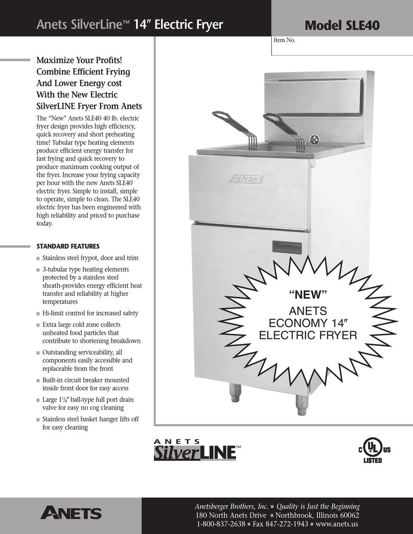
6
Table of contents
Other Anetsberger Brothers Fryer manuals

Anetsberger Brothers
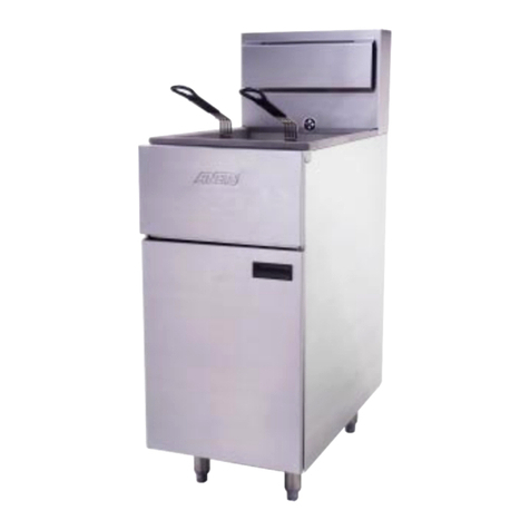
Anetsberger Brothers SLG40 Installation guide

Anetsberger Brothers
Anetsberger Brothers CF14 Installation guide

Anetsberger Brothers
Anetsberger Brothers SilverLine SLE40 User manual

Anetsberger Brothers
Anetsberger Brothers 14VF Installation guide

Anetsberger Brothers
Anetsberger Brothers GoldenFry MX14E-SFF User manual

Anetsberger Brothers
Anetsberger Brothers FM-14 Installation guide

Anetsberger Brothers
Anetsberger Brothers MX-14-2AA Installation guide