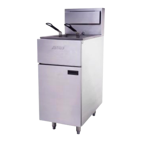
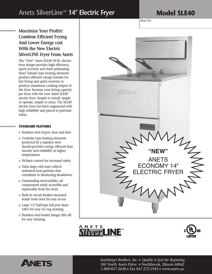
Anetsberger Brothers 14VF Installation guide

1
.4;-4
Models
14VF
14VFS
Anetsberger Brothers, Inc.
180 North Anets Drive • Northbrook, Illinois 60062 • 847-272-0770 • Fax 847-272-1943
For ANETS Factory Warranty Service • 800-837-2638
Installation,
User Operation,
&
Maintenance
Manual
Keep this Manual in a Convenient Location for Reference
FOR YOUR SAFETY
DONOTstoreorusegasolineorotherflammablevapors
or liquids inthevicinityofthisoranyotherappliance.
The Anets SilverLine
Quality Equipment For The Restaurant, Supermarket, and Bakery Industries
!
WARNING
After installation of this equipment, immediately contact your local gas
supplier to obtain information about what action to take whenever any
person smells gas. Post this information in a prominent location.
!
DANGER
Improperinstallation,adjustment,alteration,service,ormaintenancecan
cause property damage, injury or death. Read the installation, operating
andmaintenanceinstructionsthoroughlybeforeinstallingor servicing this
equipment.
!
Form: I-301
Rev. 10/01
Price: $20.00 US
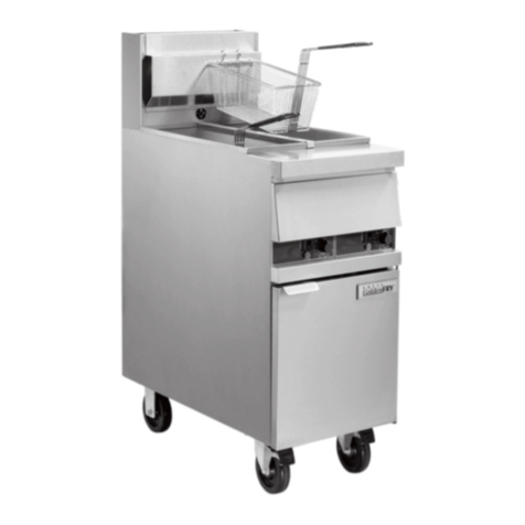
14VFSshown onstandard 6” legs

2
CONTENTS
ShippingContainerInspection ....................................................... 3
FryerGasSupplySpecifications.................................................... 3
FryerElectricalSpecifications ....................................................... 4
Figure1-FryerWiringDiagram ............................................ 4
CodeRequirements ...................................................................... 4
Figure2- FryerSiteInstallation Requirements ....................... 5
InstallationRequirements............................................................... 6
FryerRestrainingDeviceInstallationInstructions....................... 6
LegInstallationInstructions ..................................................... 7
Figure3- Leg Installation ..................................................... 7
LegLevelingInstructions......................................................... 7
CasterInstallationInstructions ................................................. 8
Figure4 - Caster Installation ................................................. 8
CasterLevelingInstructions .................................................... 8
GasConnectionInstructions.......................................................... 9
FryerOperationRecommendations ............................................. 10
FryerOperatingInstructions........................................................ 11
FryerPreparation ForUse .................................................... 11
Figure5- DrainingThe Kettle ............................................. 11
LightingProcedure................................................................ 12
Figure6-Gas Safety Valve& ControlKnob Positions ........ 12
ShutdownProcedure ............................................................ 12
FoodProductFrying TimeChart............................................ 13
DailyCleaningProcedure....................................................... 14
MonthlyMaintenanceInstructions .......................................... 15
FryerTroubleshootingGuide .................................................16 - 19
FryerWarranty ............................................................................ 20
DANGER
Read these specifications, Code Requirements, Installation Requirements, Instal-
lation Instructions, and Operating Instructions very carefully. Failure to follow the
Instructions could cause the fryer to malfunction. A fryer malfunction can result in
property damage, serious bodily injury, or death.
!

3
FRYER GAS SUPPLY SPECIFICATIONS
Please make sure that your desired fryer lo ation has gas
supply fa tors that are suitable for this produ t:
GasSupplyInletPipe mustbe½“ standard gas
line. Thegassupplyinletlineshouldbeasstraight
aspossible (fewest bendsor elbows) toobtain the
highestavailablegaspressureat thefryer. Locate
thisinletlinehorizontallyatthecenterofthe
desiredfryerlocation,approximately8¼“ above
thefloor.
1. Carefullyexaminetheshippingcartonfor
externaldamage. Whendamage isnoted,notify
thedeliverycarrier immediately. Saveallpacking
materialsfor damageclaimexamination.
2. If noexternal damageisnoted, removethe
shippingcartonfromthefryerand examinethe
SHIPPING CONTAINER INSPECTION
* -Ratingis basedon sealevel operation. Reduce rating 4% for each 1000 feetabove sealevel.
** -“W.C. = Inches, Water Column.
*** - MeasureSupply Pressure when all other gas-poweredequipment is operating.
fryer carefullyfordamage. Place thefryer ina
safelocation,if damageisnoted, sothatthe freight
damageclaimsadjustercanexamine thefryer.
3. Savetheshippingcontainerforuseduringleg/
casterinstallation. Refertothe InstallationInstruc-
tionsfor thatprocedure.
StandardAccessoriesfurnished intheshipping
cartonforthisfryerinclude:
2FryerBaskets 1 Screen
4AdjustableLegs 1DrainValveExtension
1Basket Hanger 1FlueDeflector
SUPPLY PRESSURE ***
NaturalGas Propane
3½“W.C. ** 10“W.C.
6“W.C.,minimum 11“W.C., minimum
INPUT REQUIRED:
90,000 BTU/Hr *
MANIFOLDPRESSURE
NOTE: Usingaflexibleinlet linepermitsvaria-
tioninthegassupplylinelocation,bothhorizontally
andvertically.
Anetsfryers areonly for usewith thetype of gas
specifiedon thespec plate. If afryer requires
modificationtouse agasotherthan thatwhichis
identifiedonthe fryerspec plate,contactyour
Anetsrepresentative or call(800)837-2638.
Model Features
14VF PlainSteel Fryer Kettle
Model Features
Stainless Steel Fryer Kettle
OptionalAccessoriesavailablefor thisfryer
include:
SingleorTripleFryer Baskets
1 Set (4) of Casters
14VFS
Models Covered By This Manual

4
IMPORTANT: Read the Code Requirements
and ALL installation instructions carefully,
before starting the installation. Contact the fac-
tory (800/ 837-2638) if any problems or ques-
tions arise.
Thefryerinstallationmustconformwith local
codes,or in theabsence of local codes,with the
NationalFuel Gas Code, ANSIZ223.1 (latest
edition);theNaturalGasInstallation Code,CAN/
CGA-B149.1(latest edition); or the PropaneGas
InstallationCode, CAN/CGA-B149.2(latest
edition),asapplicable,including:
a. Disconnectthefryeranditsindividualshutoff
valvefromthegassupplypipingsystemduring
anypressuretesting ofthe gassupplysystem at
testpressures in excess of ½ psig(3.45 kPa).
b. Isolatethefryerfromthegas supplypiping
systemduringanypressure testingofthegas
CODE REQUIREMENTS
FRYER ELECTRICAL SPECIFICATIONS
The ANETS Fryer Model 14VF/14VFS requires no external electric power source.
Figure1is the wiring diagram of anANETS 14VF Fryer.
supplysystem attestpressures equalto or less
than ½ psig (3.45 kPa).
c. For fryersutilizingfloorcasters,thefryerinstal-
lationshallbemadewith a connectorthat
complieswiththe Standardfor Connectorsfor
MovableGas Appliances, ANSIZ21.69
(latestedition) orCAN/CGA6.16 (latest
edition),anda quick-disconnectdevice that
complieswiththe StandardforQuick-Discon-
nectDevices forUse with GasFuel, ANSI
Z21.41or CAN/CGA 1-6.9 (latest edition).
d. Restrict themovement ofa caster-equipped
fryerbyusingalimitingdevice(forexample,a
cableattached both tothefryerandto a fix-
tureattached tothe site structure)to avoid
dependingon theconnector andthe quick-
disconnectdeviceor itsassociated pipingto
limitfryermovement.
Figure 1. Fryer Model 14VF/14VFS Wiring Diagram

5
!
Figure 2. Fryer Model 14VF/14VFS Site Installation Requirements
CODE REQUIREMENTS (Continued)
e. Install thisfryeronanon-combustiblefloor
withits back andsides at least6”awayfrom
anycombustiblewall,as showninFigure2.
WARNING
Install this fryer under a ventilation
hood that conducts combustion pro-
ducts outside the building. Venting
must comply with ANSI/NFPA 96
(latest edition).
f. Installthisfryerinalocation whereadequate
combustionandventilationairisavailable.
Keepthe areadirectly infront ofthe fryer open
foradequate air flow to theburners. DO
NOTobstruct theflow ofcombustion and
ventilationair.
g. Keepthe fryerarea free andclear from
combustiblesanddebris.
h. Attacharestraining deviceto eachfryer,to
preventtheunitfromtipping,whichcould
causesplashingofhotliquid.
From the top of the flue on
the fryer, allow a minimum
of at least 10 inches verti-
cal clearance beneath a
ventilating hood.

6
WARNING
Fryers MUST have a movement-
limiting (restraining cable) device
installed to prevent tipping that
causes splashing or spilling its HOT
contents.
NOTE: Thismovement-limitingde-
vice is to be furnished and in-
stalled by the fryer’s installing
contractor beforethe fryer is con-
nected to the gas line at its desired
location.
1. Installonerestrainingdeviceconnector
securelyintothestructurewalldirectlybehind
thefryer’sdesiredlocation (Figure2).
2. Installonerestrainingdeviceconnectoron the
rearpanel of thefryervery close tothe quick-
disconnectdevice onthe endof thefryer’s gas
line.
3. Attach oneend ofthe restrainingcable tothe
wallconnector. Attach theother endto the
fryerconnector.
4. Confirmthatthefryercannotmovefar enough
awayfromthewallto causeexcessive move-
mentoftheflexible gaslineorits associated
connectors.
FRYERRESTRAININGDEVICEINSTALLATIONINSTRUCTIONS
!
Installthefryerin accordancewiththepreceding
CodeRequirements,aswellas thefollowing
InstallationRequirements.
1. DO NOTinstallthis fryerinamobile home,
trailer,orrecreationalvehicle.
2. Install thisfryerin alocationthatallows ittobe
movedawayfrom otheradjacent appliances
forcleaningandmaintenance.
NOTE: Ifthefryer isinstalledamong
arowof appliances(“banked”), with
itsonlyconvenientmovementforward,
sufficientroommustbeavailablein
frontof thefryer topermit itssepara-
tion fromadjacentappliances for
cleaningandmaintenance.
INSTALLATION REQUIREMENTS
3. Tightlyfasten thelegs (orcasters) tothe bot-
tomofthe fryerusing thesuppliedhardware, to
preventthefryerfromtipping,wobblingor
rockingwhenit isinits desiredlocation. Refer
tothe followingLegInstallationInstructions
or CasterInstallation Instructionsforleg
orcasterattachmentandlevelinginformation.
!
CAUTION: Hood make-up air
MUSTNOT flowinamannerthat
restrictsorimpedesthe naturalflow
of combustionorventilationair.
4. Confirmthattheairfromtheventilationhood
flowingnearthefryerafterinstallationisNOT
blowingontherearof theunit, toprevent
affectingtheburnerflamesandpossiblycausing
controldamage.
7
INSTALLATION REQUIREMENTS (Continued)
Figure 3. Ty ical Leg Installation
LEG LEVELING INSTRUCTIONS
1. Move thefryer toits desiredlocation.
WARNING
The fryer MUST NOT tip, rock or wob-
ble,toavoid splashing or spillingitsHOT
shortening contents during operation.
2. Turnthe screw-typeleg adjustmentends as
necessarytolevelthe fryer,untilNOtipping,
rocking,orwobblingisevident.
3. Perform the “FryerRestrainingDevice
InstallationInstructions.”
!
LEG INSTALLATION
INSTRUCTIONS
1. Flattentheshippingcarton(afterunpackingthe
fryerand itsparts andaccessories) forfryer
surfaceprotectionduringleginstallation.
2. Position theside ofthefryerflaton thecarton,
exposingthefryerbottommountingbrackets
forleginstallation,asshownin Figure3.
3. Placethelegmountingplateflushagainstthe
mountingbracketon thefryerbottom.
4. Insert onemountingscrew throughtheproper
holeintheleg mountingplateand startit into
theproperhole inthefryer mountingbracket.
5. Screwthemountingscrewseveralturns into
themountingbracket.
6. Repeat steps4and 5untilallfour mounting
screwsfor each legare inplace.
7. Tightenthefourmountingscrewsevenlyand
securelytoholdthelegmountingplateagainst
thefryer bottommounting bracket.
LEG INSTALLATION
INSTRUCTIONS (Continued)

8
CASTER LEVELING INSTRUC-
TIONS
1. Move thefryer toits desiredlocation.
2. Determine whetherthefryer tendsto wobble
orrock whenin itsdesired location. Ifit
does, perform steps 3 through 9. If it does
not, skip to step 10, then proceed to the
InstallationInstructions.
WARNING
The fryer MUST NOT tip, rock or wob-
ble,toavoid splashing or spillingitsHOT
shortening contents during operation.
3. Determinewhichcasterrequiresadjustment
andtheapproximateamount ofchange
requiredtolevelthefryer.
4. Position theside ofthe fryeron theship-
pingcarton,exposing thebottomof thefryer
withthecastermounting plates(Figure5).
5. Completelyunscrewthescrewsholdingthe
castermountingplatethatrequiresleveling
adjustment. Retainthescrewsforlater
reassembly.
!
INSTALLATION REQUIREMENTS (Continued)
Figure 4. Ty ical Caster Installation
CASTER INSTALLATION
INSTRUCTIONS
1. Flattentheshippingcarton(afterunpackingthe
fryerand itsparts andaccessories)for surface
protectionduringcasterinstallation.
2. Position theside ofthefryerflaton thecarton,
exposingthefryerbottommountingbrackets
forcasterinstallation,asshowninFigure 4.
3. Mount lockingcastersonthefront ofthefryer
andfixed casterson therear,by placing each
castermountingplateflushagainstthemounting
bracket on thefryerbottom.
4.Insertone mountingscrew throughthe proper
holeinthe castermounting plateand startit
intotheproperholeinthe fryermounting
bracket.
5. Screwthemountingscrewseveralturns into
themountingbracket.
6. Repeat steps4and 5untilallfour mounting
screwsfor each legare inplace.
7. Tightenthefourmountingscrewsevenlyand
securelytoholdthe castermountingplate
againstthefryermountingbracket.

9
GAS CONNECTION INSTRUCTIONS
InstallingyourANETS Fryer requiresthe fol-
lowingprocedure, afterits legs orcasters arepro-
perlyattached and itisinitsdesired location.
1. Ensure thatthegas safetyvalve controlknob
inthe fryerhas itsOFF positionnext tothe
valvemark.
2. Ensurethatthegassupplyinletlinevalveis
closed(crosswiseto thelinedirection).
3. Ensure thatthe fryer’s thermostatis setto
OFF.
4. Connect the½”gassupply linetothegas line
adapteron the lowerrear of thefryer.
5. Turnthe gassupply linevalveON; then,check
allgassupplylinejointsandcouplingsfor
leaksusing soap suds ora leak-check solu-
tion,afterthe fryerisinitsdesiredlocation.
6. Refer toFryer OperationRecommenda-
tionsand FryerOperatingInstructions to
beginusing yourANETS Fryer.
CASTER LEVELING INSTRUCTIONS (Continued)
INSTALLATION REQUIREMENTS (Continued)
6. Reinserteachmountingscrewthroughthe
castermounting plate;next, placea spacerof
therequiredsize onthescrew beforeinserting
thescrewinto thefryermountingbracket.
7. Repeatstep 6 forall remainingscrews.
8. Tightenallfourmountingscrewsevenlyand
securelyagainstthecastermountingplateinto
thefryerbottommountingbracket.
9. Returnthe fryerto itsdesired location. Lock
thefrontcasters topreventfryer movement
andcheckagain forwobblingor rocking.
Repeatsteps 4through 8 untilno wobbl-
ingor rockingoccurs. When thefryer no
longerwobbles or rocks, performstep 10.
10. Next,perform the“Fryer Restraining
DeviceInstallationInstructions.”
!
WARNING
DO NOT usea flame to checkfor leaks.

10
Pleaseobservethefollowingrecommendations to
obtaintheoptimum resultsfromyour ANETS
Fryer.
DANGER
Avoid moving the fryer while it contains
HOTshortening. Draintheshorteningfrom
thefryerbeforemovingitforservice,clean-
ing or maintenance to avoid spilling or
splashing. Burnsfrom hotshorteningcan
causeseriousinjury ordeath.
A. An ANETS Model 14VF or 14VFS
Fryerisdesignedforoperation witha kettle
filledwithapproximately35to40pounds of
liquidshortening. (Thisisapproximately
3½to 5gallons.)
CAUTION: DO NOT melt solid
shorteninginthis fryer because
themelting can damage the kettle,
whichwillvoidthefryerwarranty.
FRYER OPERATION RECOMMENDATIONS
Shorteningmustbemelted intotheliquidstate
beforeit can be used in an ANETS Fryer.
B. Scheduleregular cleaningofthefryerto
ensurelong-termsatisfactoryoperation.
Referto the DailyCleaningProcedure,
laterinthismanual.
C. Beforeservicingandmaintenance,allowthe
fryerto cool. ALWAYS shutoffgas to the
fryerwhileworking onit,to prevent burns.
D. Contact the factory (800-837-2638) for war-
rantyserviceauthorization. [Alwaysnotify
thefactory the next businessday about
‘after-hours’warranty service.] Contact
yourlocalrestaurantequipmentservice
agencyfor otherservice, repairs,ormainte-
nanceactivities,as necessary.
CAUTION
DO NOT attempt to operate this fryer during an interruption of gas
service. Turnallfryercontrols toOFF,includingthe gascontrolvalve
knob, then close the gas supply line valve. When notified that the
interruption of gas service has ended, perform the Lighting Proce-
dure(laterinthis manual).
DANGER
NEVER operate this fryer when its flue is blocked because
thecombustion productscancause injuryto personnel.
!
!
!
!

11
Beforeusingthenewly installedfryerforfood pre-
paration,cleantherustpreventive materialfromthe
kettle:
1. Thoroughlywipetheinteriorofthekettle
withclean cloths. Openthe front dooron
thelower portionofthe fryerto access the
drainballvalve.Open thedrainballvalve
(byaligningthevalvehandlewiththedrain
ballvalve)andwipe theentiredrainlineclear
ofrustpreventivematerial.
2. Close thedrainball valve(turnthe valvehan-
dlecross-wiseto thedrain ballvalve). Fill
thekettlewithwatertoabout 3“ fromthe
top. Add 1 to 2 cups of low sudsing soap
powder,washingsoda (trisodiumphos-
phate),or deep fat fryerkettle cleaner.
3. Perform theLightingProcedureforthe
fryer. (Refer tothe LightingProcedure
laterinthismanual.)
4. Set the thermostat to 190°F. Heat, but DO
NOT boil the water. Stir the water to dis-
solvethecleaningmaterial.
5. Clean thefryer kettlefor atleast20 minutes.
Useasmallhandmop (anoptional brushcan
be ordered for this purpose) toclean the
upperportion ofthe kettle(abovethe3“
waterline)andthe toprim ofthe kettle.
6. ShutdownthefryerusingtheShutdown
Procedurefor the fryer. Refer totheShut-
downProcedurelaterinthismanual. Allow
thewatertocoolslightly.
7. Open thefront doorand mountthedrain
extensiontothe drainballvalve. Position a
container(bucket)capable of holdingVERY
HOTcleaningsolutionbeneath theendof the
drainextensiontoholdthecleaningsolution
beingdrained,as shownin Figure5.
FRYER PREPARATION FOR USE
FRYER OPERATING INSTRUCTIONS
Figure 5. Draining The Kettle
Normaloperation ofan ANETS Fryer requiresthat thekettle isfilled withliquid shortening toabove the
lowerindentlevel markedontherearofthekettle, beforelighting thefryer’smainburners.
CAUTION: ShorteningMUSTbein liquidform toavoid scorchingor discolorationand possible
damageto thekettle. Damagecausedbymelting solidshortening will NOTbe coveredby thewarranty.
8. Open thedrain ballvalve SLOWLY, toavoid
splasheswhiledrainingthecleaningsolution
fromthekettle.
9. Closethedrainballvalve(valvehandle
cross-wise)andremovethedrainextension.
Closethe front door.
10. Safely disposeofthecleaningsolution.
11. Fill thekettlewith watertoabout3“from
thetop. Add 2cups of vinegarto neutralize
thecleaningsolution.
12. Repeat steps 3 through10 of thisprocedure.
13. Thoroughlywipe theinteriorofthekettle and
thedrainballvalvewithclean,dry,wiping
clothsto removeALL water.
14. Drythe kettlethoroughlybecause anyre-
mainingwatercan causespatteringof hot
shorteningwhenthekettleislaterfilledand
heated.
!
FRYER PREPARATION FOR USE
“BOILOUT” INSTRUCTIONS (Continued)

12
SHUTDOWN PROCEDURE
NOTE:Shutdown is recommendedat the end of
aworkdayor wheneverno fryingisscheduled for
aperiod of severalhours. To preventdamage, the
fryerMUSTalsobe shutdownwhenever thereis
noshorteninginthekettle.
1. Turnthethermostat knobtoOFF.
2. Turn thegascontrol valveknobtoalignthe
PILOTsettingwiththevalvemark.
Observethatthe mainburners’flames go
out.
3. Press downand turnthe gas controlvalve
knobtoalign theOFFsetting withthevalve
mark.
Observethat thepilotflame goesout.
NOTE: For extended periods of non-use
orwhenservicing thefryer,close thegas
supplylineinletvalvetothefryerbyturning
thegasvalve handlecross-wise withthegas
linepiping.
LIGHTING PROCEDURE
NOTE: Thegasline ofa newfryerinstallation
maycontainaconsiderableamount ofairwhich
willhinderimmediatelighting. Youmayhaveto
pressin thecontrolknob aslong asseveral minutes
beforethepilotflameburns steadily.
1. Open thefront door andensure that the
fryer’sthermostat knob isset to OFF.
2. Open thegassupply lineinletvalvetothe
fryerbyaligningthegasvalvehandlewiththe
gaslinepiping.
3. Turn thegascontrol valveknobtoalignthe
PILOTsettingwiththevalvemark.
Figure6 showsthe possiblecontrol knob
positions.
4. Press, andhold down, the valve control knob
toallowpilot gasto flow. Applyalighted
FRYER OPERATING INSTRUCTIONS (Continued)
Figure 6. Gas Control Valve & Knob Positions
OFF PILOT ON
Valve
Mark Valve
Mark Valve
Mark
OFF
P
I
L
O
T
ON
OFF
ON
P
I
L
O
T
OFF
P
I
L
O
T
ON
matchtothe endofthe pilotburner,until the
pilotflamelights.
NOTE: Abutanelighter may also be
usedto lightthepilot flame.
Continueholdingdownthe controlknobfor
atleast30 secondsuntilthepilotflame burns
steadily,withoutgoingout.
5. Release thecontrol knob andobserve that
thepilotflameremainslighted.
6. Turn thegascontrol valveknobtoalignthe
ONsettingwith thevalvemark.
7. Turn thethermostat knobto thedesired
temperature. Observethat thefryer’smain
burnerslightto heatthekettle.

13
FRYER OPERATING INSTRUCTIONS (Continued)
Load the fryer basket with the
food product while the basket is
not in the hot liquid shortening.
DO NOT overload the fryer
basket. Load only a premeasured
quantity of food product (1½ lb,
typically; less, if smaller portions
are desired). Place the loaded
fryer basket into the hot liquid
shorteningcarefully to avoid
splashing.
When the basket of food product
has reached the desired point of
‘doneness’, lift the basket from
the hot shortening and hang the
basket on the basket hanger to
let it drain for approximately 15 -
30 seconds before serving.
NEVER increase the thermostat
setting above the recommended
setting to reduce the cooking
time; this will produce a lower
quality product and will cause
more rapid shortening break-
down.
RECOMMENDED FRYING TIME FOR
POPULAR FRIED FOODS
* - Use a second basket on top of the chips in the bottom basket,
to keep them within the hot shortening; otherwise, they float
before cooking completely.
Food Product
Breaded Foods
Cheese Sticks
Mushrooms
OnionRings
French Fries (Typical 1½ lb Load)
Raw to Done 1/4” cut
Blanched,only 1/4” cut
Browned,only 1/4” cut
Raw to Done 3/8” cut
Blanched,only 3/8” cut
Browned,only 3/8” cut
Raw to Done 1/2” cut
Blanched,only 1/2” cut
Browned,only 1/2” cut
FrozenFish (Filletsor Sticks)
Tortilla Chips*
340 3
2½ - 3
2½ - 3
5
2½
2½
6
3
3
7
4
3
4 - 7
2 - 2½340
Frying
Time
(minutes)
ANETS
Fryer
(° F)

14
DAILY CLEANING PROCEDURE
NOTE: Cleaning is recommendedat the end of a
workdayto prepare the fryerfor proper operation
thenext timeit is tobe used.
DANGER
Avoid moving the fryer while it contains
HOTshortening. Draintheshorteningfrom
thefryerbeforemovingitforservice,clean-
ing or maintenance to avoid spilling or
splashing. [Refer to steps 1 through 7.]
BurnsfromHOTshorteningcancausese-
riousinjuryordeath.
1. Openthe frontdoor of thefryer. Attach the
drainextensiontothedrain ballvalve.
2. Perform theShutdownProcedure. Ensure
thatthegassupplyline inletvalveisclosed
(handlecross-wisetopipeline) andthe pilot
flameisextinguished.
3. Position asteeldrum [NEVERuseplastic!]
withafiltercone directlybeneaththedrain
extensionend.
4. Slowly openthedrain ballvalveto drainthe
HOTshortening.
5. Remove thefryer basketsand screenfrom
thekettle. Remove thebasket hangerfrom
theflue. Clean,and rinse,these itemsinthe
sink. MAKESURE thattheseitems are
completelydrybeforetheirnextuse.
6. Clear anysedimentblocking thekettledrain.
Flushoutallsediment inthebottomof the
kettlebypouringfilteredliquidshortening
intothekettleuntiltheshorteningbeing
drainedrunsclear.
7. Close thedrain ballvalve,after thekettleis
completelyemptyofshorteningand sedi-
ment. Detachthe drainextension. Clean,
rinse,anddry itbefore storing.
FRYER OPERATING INSTRUCTIONS (Continued)
WARNING
Wait until the kettle has cooled
beforeperforming step8,to avoid
injury from burns.
8. Thoroughlywipethekettleinteriorusing
cleancloths.
9. Periodically performthe“BOILOUT”
Instructionstoensurethorough cleaningof
thekettle. ( Refertothe earlierFRYER
PREPARATION FOR USEsection.)
10. Returnthe fryertoits normaloperatingloca-
tion,ifit wasmovedforcleaning,and recon-
nectboth thegas supplylineandthemove-
ment-limitingcable. (Forcaster-equipped
fryers,lock thelocking casterstoprevent
movement.)
11. Refillthekettlewithfiltered(orfresh)liquid
shorteningtothe desiredindent markonthe
rearwall ofthe kettle,onlyif fryeroperation
istocontinueduringasubsequent shift.
Otherwise,meltshorteningintoitsliquidstate
andrefillthe kettlebeforefryeroperation is
scheduledduringthenextnormalworking
shift.
12. Attachthe basket hanger tothetop of the
backsplashpanel. Returnthe screenand
fryerbaskets totheir proper positionson the
baskethanger.
13. Performthe LightingProceduretoreturn
thefryer tooperation, whendesired.
DAILY CLEANING PROCEDURE
(Continued)
!
!

15
NOTE: Regularmaintenance isrecommendedto
keepthe fryeroperatingproperly.
Onceeachmonth, beforebeginningfryeropera-
tion,checkthe flue(behindthe backsplashpanel)
toensure thatit isclear andfree ofobstructions,
enablingexhaustcombustiongasestoflowfreely
towardthe ventilationhoodarea. DO NOTallow
thefluetobecomeexcessivelydirty.
Monthly,observetheconditionoftheventilation
hood. Ifit shows evidenceof a great dealof
greasyresidue,remove (clean)the residuetoallow
freeflowofventilationair.
MONTHLY MAINTENANCE INSTRUCTIONS
FRYER OPERATING INSTRUCTIONS (Continued)

16
FRYER TROUBLESHOOTING GUIDE
Pilot flame does not
staylighted. 1. Dirty/sooty pilot burner.
2. Low gas supply pressure [less than 6”
W.C. for natural gas (11”W.C. for pro-
pane) when all other gas-powered equip-
ment is operating.].
3. Pilot flame too small to heat thermo pile.
4. Pilot flame ‘wavering’ (being blown about
by a draft).
5. Improper thermopile output voltage (must
be at least 180 millivolts, measured at the
thermocouplejunction block).
6. High-limit thermostat problem has shut off
the gas.
7. Gas control valve has failed.
1. Clean the pilot burner. Perform
the Lighting Procedure.
2. Measure the gas supply pres-
sure.
Contact your local gas supplier
to obtain adequate gas supply
volume and pressure.
3. Adjust the pilot valve (part of
the gas safety valve) to in-
crease the flame size: Un-
screw and retain the large
threaded cover; turn the pilot
valve adjustment screw two
turns counterclockwise;
reinstall the threaded cover.
4. Block or redirect the draft, to
keep the flame burning steadily.
5. Replace the thermopile.
6. Check for, and repair, any dam-
aged high-limit thermostat wir-
ing. Otherwise, test the high-
limit thermostat by bypassing
the high-limit thermostat (black
and blue wires) at the gas con-
trol valve with a jumper wire.
Next, perform the Lighting Pro-
cedure, to check whether the
pilot flame lights. If the pilot
flame lights and stays lit, the
high-limitthermostat has failed
and must be replaced.
7. Replace the gas control valve.
PROBLEM CAUSE REMEDY
All service (repairs or part replacement) must be performed by a qualified Service Agency.
CAUTION: DO NOT return
the fryer to normal operation
withits high-limit thermostat
bypassed.
!

17
FRYER TROUBLESHOOTING GUIDE (Continued)
Pilot flame goes out
repeatedly. 1. Low gas supply pressure [less than 6”
W.C. for natural gas (11”W.C. for pro-
pane) when all other gas-powered equip-
ment is operating.].
2. Loose thermocouple or high-limit thermo-
stat connection(s) on gas control valve.
3. Pilot flame does not continuously touch
the thermocouple because of excessive
air flow around the pilot burner assembly.
4. High-limit thermostat problem has shut off
the gas.
1. Measure the gas supply pres-
sure.
Contact your local gas supplier
to obtain adequate gas supply
volume and pressure.
2. Check and tighten the connec-
tions.
3. Block the excessive air flow to
make the pilot flame contact
the thermocouple.
4. Check for, and repair, any dam-
aged high-limit thermostat wir-
ing. Otherwise, test the high-
limit thermostat by bypassing
the high-limit thermostat (black
and blue wires) at the gas con-
trol valve with a jumper wire.
Next, perform the Lighting Pro-
cedure, to check whether the
pilot flame lights. If the pilot
flame lights and stays lit, the
high-limitthermostat has failed
and must be replaced.
PROBLEM CAUSE REMEDY
Main burners do not
ignite. 1. Gas control valve knob set to OFF or
PILOT.
2. Low gas supply pressure [less than 6”W.C.
for natural gas (11”W.C. for propane)
when all other gas-powered equipment is
operating.].
3. Pilot burner problem.
4. Thermostat control set below the tempera-
ture of the liquid shortening in the kettle.
1. Perform the normal Lighting
Procedure. Turn the gas
control valve knob to ON to
light the main burners.
If the burners do not light, the
gas safety valve has failed and
must be replaced.
2. Measure the gas supply pres-
sure.
Contact your local gas supplier
to obtain adequate gas supply
volume and pressure.
3. Refer to the preceding Pilot
Burner problems and use the
correct remedy.
4. Increase the thermostat setting
until the burners light. If this
setting is greater than the
desired temperature, reset the
thermostat.
!
CAUTION: DO NOT return
the fryer to normal operation
withits high-limit thermostat
bypassed.

18
Liquidshortening does
not reach the desired
temperature for frying.
1. Low gas supply pressure [less than 6”W.C.
for natural gas (11”W.C. for propane)
when all other gas-powered equipment is
operating], causing reduced heat from main
burners.
2. Low gas manifold pressure [less than 3½”
W.C.for natural gas (10”W.C. for pro-
pane).
3. Loose knob on thermostat; or thermostat
requires calibration (temperature setting
differs by about 10°F from the measured
shortening temperature).
Main burners do not
stopburning. 1. Thermostat has failed.
2. Gas control valve has failed.
1. Turn the thermostat control
knob to OFF. If the burners
do not quit burning, the ther-
mostat has failed and must
be replaced.
2. Turn the gas control valve knob
to OFF. If the burners do not
quit burning, the gas control
valve has failed and must be
replaced.
1. Measure the gas supply pres-
sure.
Contact your local gas supplier
to obtain adequate gas supply
volume and pressure.
2. Measure the gas pressure at
the fryer’s manifold pressure
tap. Adjust the manifold pres-
sure (see Figure 6), as neces-
sary: [a] Unscrew (and re-
tain) the threaded Main Burner
Regulator Adjustment Cover.
[b] Use a flat-blade screw-
driver to turn the regulator
adjustment screw (clockwise to
increase; counterclockwise to
decrease) to reset the pressure
adjustment. [c] Reinstall, and
tighten the Regulator Adjust-
ment Cover, when finished.
3. Stir the shortening to mix the
hot shortening with some from
the lower ‘cool zone’ and allow
it to sit for 5 minutes. Turn the
thermostat knob until it ‘clicks’
on (causing the main burners to
flame); note the setting where
this occurs. Turn the thermo-
stat knob until it ‘clicks’ off
(causing the main burners to go
out); note the setting where this
occurs. Repeat this tempera-
FRYER TROUBLESHOOTING GUIDE (Continued)
Main burners do not
ignite. (Continued)
PROBLEM CAUSE REMEDY
5. Gas control valve has failed. 5. Replace the gas control valve.

19
NOTE: A Parts List for each ANETS Fryer is among the items shipped with each fryer. If an
additional copy of this list is needed, please contact the factory as directed on the back cover.
FRYER TROUBLESHOOTING GUIDE (Continued)
PROBLEM CAUSE REMEDY
Liquidshortening does
not reach the desired
temperature for frying.
(Continued)
3. Loose knob on thermostat; or thermostat
requires calibration (temperature setting
differs by about 10°F from the measured
shortening temperature). (Continued)
3. (Continued)
ture ‘click points’ step at least
three times to ensure that the
shortening temperature has
stabilized.
Measure the temperature of
the shortening by inserting an
accurate thermometer about
4 inches into the shortening to
measure its temperature. If the
temperature difference be-
tween the measured tempera-
ture and the thermostat setting
is more than 15°F the thermo-
stat is failing and must be
replaced.

20
Keep this Manual in a Convenient Location for Reference
Anetsberger Brothers, Inc.
180 North Anets Drive • Northbrook, Illinois 60062 • 847-272-0770 • Fax 847-272-1943
Toll-freeCustomer & WarrantyService: 800/837-2638
Form: I-301 Rev. 10/01 Price: $20.00 US
LIMITEDWARRANTY
ANETSBERGERBROTHERS,INC.,Northbrook,Illinois,USA,certifiesthatallequipmentofitsmanufac-
tureis,to thebest ofitsknowledge, freefromdefectivematerialand workmanship.
ANETSBERGERBROTHERS,INC., agreestoreplaceany integralpartof itsequipmentthat provesdefec-
tivewithin15monthsof dateoforiginalshipmentfrom thefactory,or12months fromthedateofinstallation,
whichever is sooner. Buyer must return the defective part to the factory, freight prepaid, for inspection.
AnetsbergerBrothers, Inc., further agreesto assume the costof installing said replacementpart within the
sameperiod.
All frypots are covered by the warranty above for the first year of operation. Various models have an
extendedwarrantythatcoversthe replacementof thefrypotonly. Seethe individualspecification sheetsfor
details.
Overtime charges,calibration, adjustmentsand abnormalinstallation chargesshall notbe atthe expenseof
AnetsbergerBrothers,Inc.
Theconditionsand warranty expressed above are validonly if equipment has been properlyinstalled and
operated. Noother warranty, expressed or implied,shall govern equipmentmanufactured by Anetsberger
Brothers,Inc. Under no circumstances shallAnetsberger Brothers,Inc., be liable forloss of profits orany
director indirectcost,expenses, lossor damages arisingout ofdefectsin orfailure of theequipment orany
partthereof.
This manual suits for next models
1
Table of contents
Other Anetsberger Brothers Fryer manuals

Anetsberger Brothers
Anetsberger Brothers FM-14 Installation guide

Anetsberger Brothers
Anetsberger Brothers 14G Installation guide

Anetsberger Brothers
Anetsberger Brothers GoldenFry MX14E-SFF User manual

Anetsberger Brothers
Anetsberger Brothers SLG40 Installation guide

Anetsberger Brothers
Anetsberger Brothers SilverLine SLE40 User manual

Anetsberger Brothers
Anetsberger Brothers CF14 Installation guide

Anetsberger Brothers
Anetsberger Brothers MX-14-2AA Installation guide