Copyright © 2019 AudioNote Kits
www.AudioNoteKits.com
Page 7
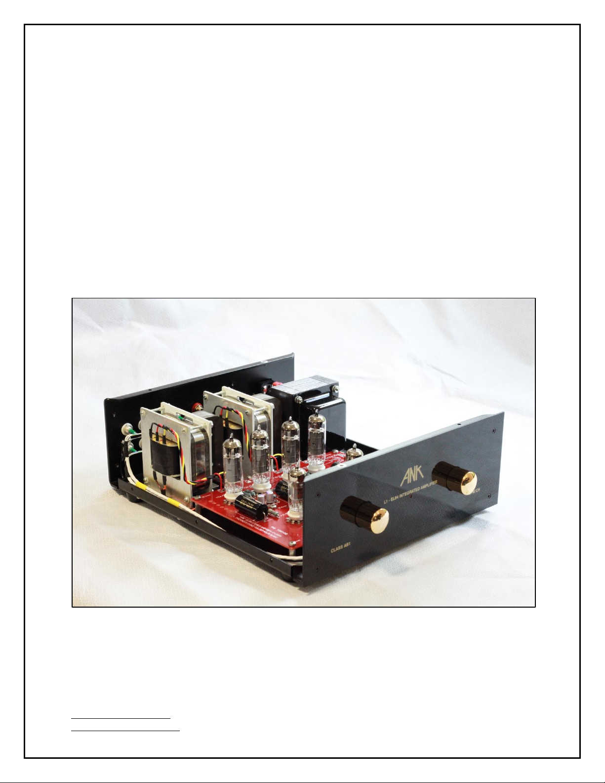
1.2 Evolution of the L1 EL84 Integrated Amplifier V2
ANK Audio Kits is pleased to announce the newly updated L1 EL84 Integrated Amplifier V2.
Who doesn't love listening to the rich and revealing sound of your favorite CDs, streaming, and
other source(s) through a beautiful high quality amplifier.
“I have always wanted to introduce a top quality integrated amplifier kit with
the gorgeous EL84 pentode that is easy to build for the first timer, affordable,
and an ultimate audiophile experience! We succeeded! After many years of
thought and development the new low cost L1 EL84 Integrated is a reality.”
Brian Smith
The amplifier's 6-tube design includes a large Mains transformer, 4 line-level inputs, 2 ECF80
driver tubes, and 4 EL84 Power pentode output tubes producing 17 beautiful class AB1 watts
and a dead quiet operation. The El84 has more gain than is usual in a power pentode,
producing full output from a relatively small drive signal. Many audiophiles love this tube for
its distinctive, articulate sound. All you need to do is attach your speakers, plug in some
sources, turn it on, and away you go!
We hope you will be very happy with this kit. It uses top of the line parts all the way, including
a 3mm thick aluminum chassis powder coated black for serious robustness and high quality
Mains and output transformers —EI-Core or triple C-Core, with high gloss black covers,
custom-designed and manufactured for Audio Note (UK). The majority of components fit onto a
single thick high quality printed circuit board (PCB), expertly engineered and tested. To keep
your amplifier perfect over many years, or do periodic checks for maintenance, there are test
points for tube cathode voltages and High Voltage.
This is a fun build and ideal for the first-time builder. The kit is not overly complex and we
believe that this manual will enable you to assemble it successfully. A good first step is to view
the parts list included on the disk and do an inventory of all the parts. If there are any
discrepancies please contact audionotekits@rogers.com or call (613) 822-7188. Then you will
start by installing the large Mains transformer in the chassis and hooking up the AC socket
and PCB, and rocker switch. Our manual will walk you carefully through all the required steps
—then, you can start on the build of the large PCB. The goal, of course, is to carefully install
the resistors, capacitors and other parts into the correct positions and to make sure that the
wiring between the various functional parts of the amplifier (what we call the "interwiring") is
correct. To help you we have included many pictures, including high resolution pictures on
disk, that you can use to get things just right. And finally, we'll install the output transformers
and the various input jacks and front panel controls and then test everything.
One of the key aspects of ANK Audio Kits success is our terrific support. We're always here to
help you. So, rest assured, we'll make sure you succeed!